xTool Store
Common Processing Problems
Updated Jan 9,2026
Updated Jan 9,2026
Troubleshoot no laser beam scenario
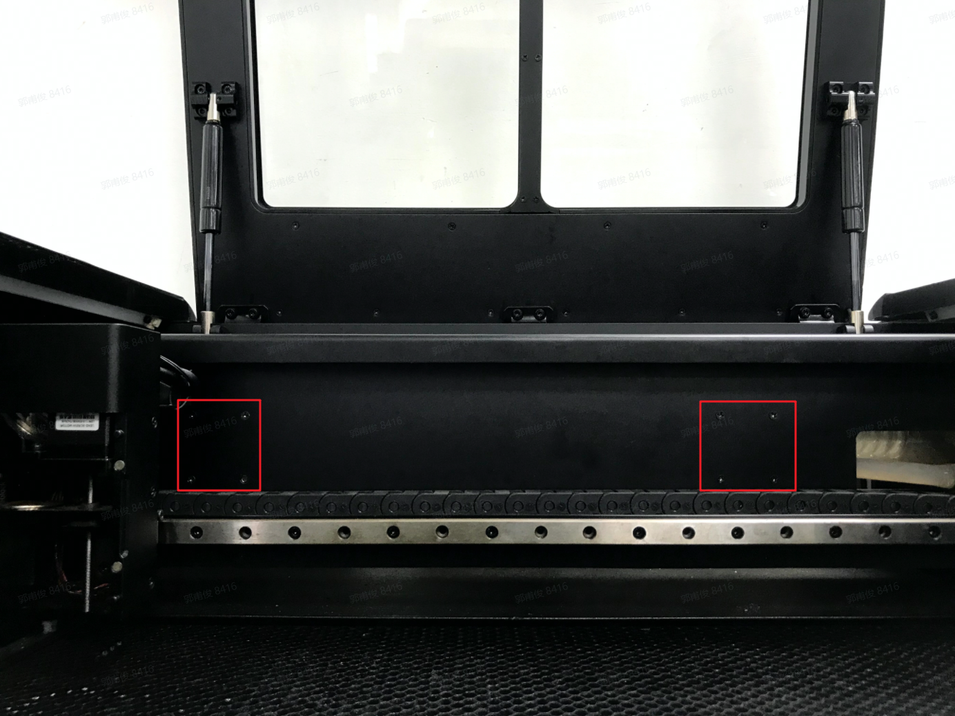
Shut down the machine, loosen the 8 screws of the laser tube protective cover (as shown in the figure below), remove the laser tube cover (move the cover to the left or right), and observe whether the appearance of the laser tube is obviously damaged (click here to check the video for reference, which shows how the water inside can flow freely after the laser tube is damaged).
- If the laser tube is visibly damaged (leakage or broken inner tube), replace the laser tube.
- If not, please refer to the following steps for troubleshooting.
- Make sure that the software and firmware are the latest version(click herefor reference), you can refer to the video below to check.
- Turn on the machine and connect it to the Laserbox software.
- Put in the consumables and set the processing parameters (power 100%, speed 1mm/s).
- Refer to the video(click here) to observe whether the laser tube emits light normally(The brightness of the laser tube in the normal working state is completely different from the brightness in the fault state.)
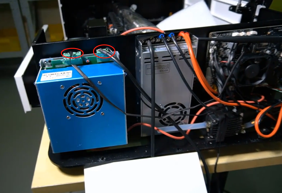
- If the light cannot be emitted normally, you can refer to the video(click here) to check whether the laser power control wire is loose(try to replug them). If there is no obvious looseness, replace the laser tube/laser power supply one by one.
- If the light can be emitted normally, refer to the video(click here) to check whether the optical path is shifted, and whether the reflector/focusing mirror is installed backwards/falls off(click hereto learn more about the mirrors).
Failed to cut through official materials, why?
- If it is a non-official consumable, try to change the parameters (increase the power and slow down the speed) to verify whether it is due to power decay.
- Make sure the consumables are flat and there are no other foreign objects on the honeycomb board.
- Recommend cleaning the lens.
- Confirm whether the machine has been maintained and whether the focusing mirror is installed backward, the correct is convex side up, concave side down installation.
Why is there an offset between the graphics processing position and the actual position?
- Check whether the camera fixing plate is loose or fallen off.
- Due to the characteristics of the fisheye camera, the material should be placed directly below the camera as much as possible to avoid edge distortion affecting camera recognition.
- Try to do position calibration(click here to check how to do it).
- If there is still an offset problem after the position calibration, try to do a primary calibration(click here for reference).
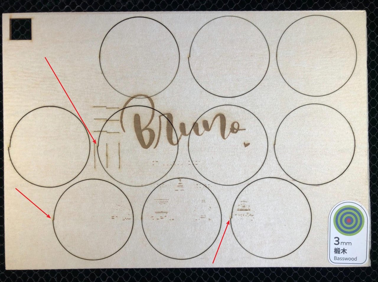
Why does the processed graphic appear deformed (graphics are not closed or the ratio is not right)?
After using the machine for a long time, the X-axis may lose steps(very low probability). You can refer to the steps below to troubleshoot the problem.
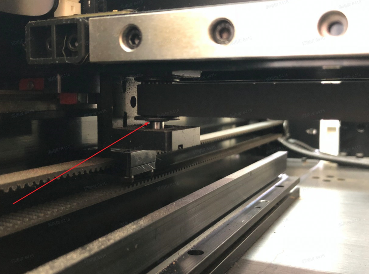
- Check for foreign objects in the driven pulley (near the X-axis belt).
- Check whether the distance between the upper and lower sides of the driven wheel is consistent (refer to the following picture).
- Readjust the belt tightness (click here to see how-to).
Preview
Was this page helpful?
0 out of 3 found this helpful
Help Ticket
Use this help ticket to submit your issue. We will respond within 1 business day
Submit a Ticket Tags
Help Ticket
Use this help ticket to submit your issue. We will respond within 1 business day
Submit a Ticket Services & Help
Learn & Education

Copyright © 2025 xTool All Rights Reserved.