Quick Start Guides in different languages
Note: From the Quick Start Guide, you can view the item list, product structure, specifications, indicators and buzzer explanation, as well as instructions on device installation, and fundamental maintenance.
List of items
xTool F2 Ultra | Touchscreen controller | Pipe | Power adapter |
Power cable | USB cable | Key | Slatted panel |
L-shaped positioning piece | Lint-free cloth | Screwdriver | Sample materials |
|
| ||
Quick Start Guide | Safety Instructions |
|
|
Meet xTool F2 Ultra
Product structure
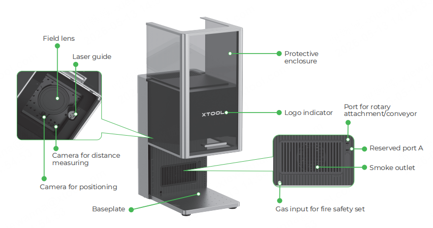
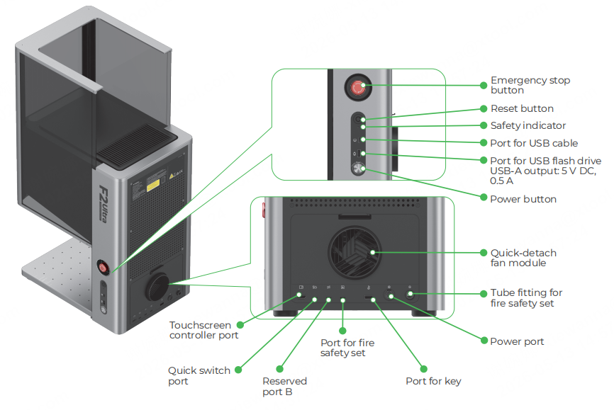
Note: Reserved port A and port B function differently and can not be used interchangeably.
Note: By gripping on the handholds, you can easily move the machine.
Touchscreen controller
|
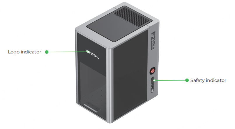
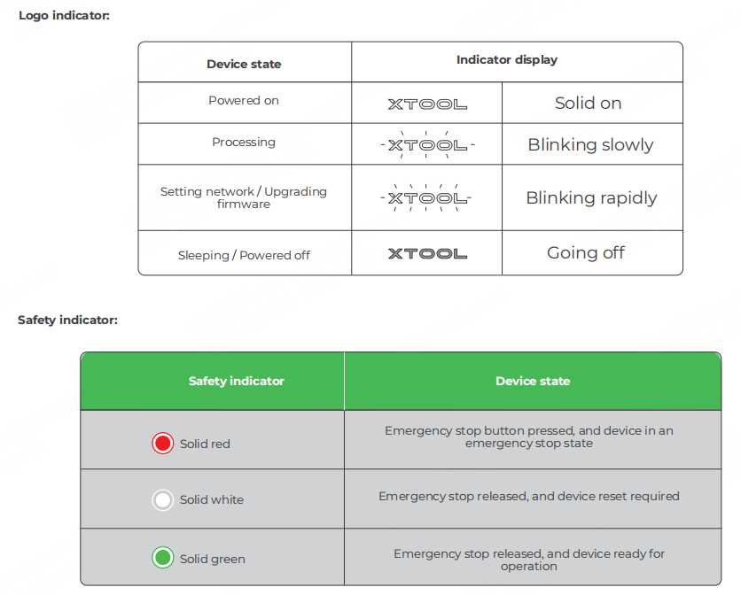
Common machine states and indicator display
Specifications
Product name | xTool F2 Ultra | Working laser | 40 W blue-light diode laser 60 W infrared MOPA laser |
Size (W × D × H) | 294 mm × 429 mm × 520 mm | Working laser wavelength | Blue-light laser: 445 ± 15 nm Infrared laser: 1064 ± 5 nm |
Voltage | 110 V / 220 V | Internal working area | 220 mm × 220 mm |
Connection mode | Wi-Fi, USB, IP | Maximum processing speed | 15,000 mm/s |
Note: The single-laser xTool F2 Ultra includes only a 60 W infrared MOPA working laser. The 40 W blue-light diode laser is not included in the single-laser model.
Install xTool F2 Ultra
- Pull the tag string down to detach the field lens protector.
Note: Ensure that the protector is removed every time before you use the machine. If you won't use the machine for a long period of time, you can install the protector back to prevent the field lens from getting dusty.
- Insert the key.
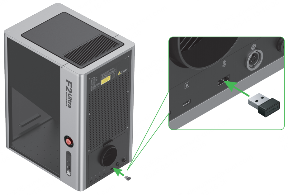
Note: You can use the key either as an access-control key or a remote interlock connector.
Access-control key
Removing the key can disable the machine's processing and related functions.
Remote interlock connector
For detailed instructions, visit support.xtool.com/article/1367.
- Connect the touchscreen controller.
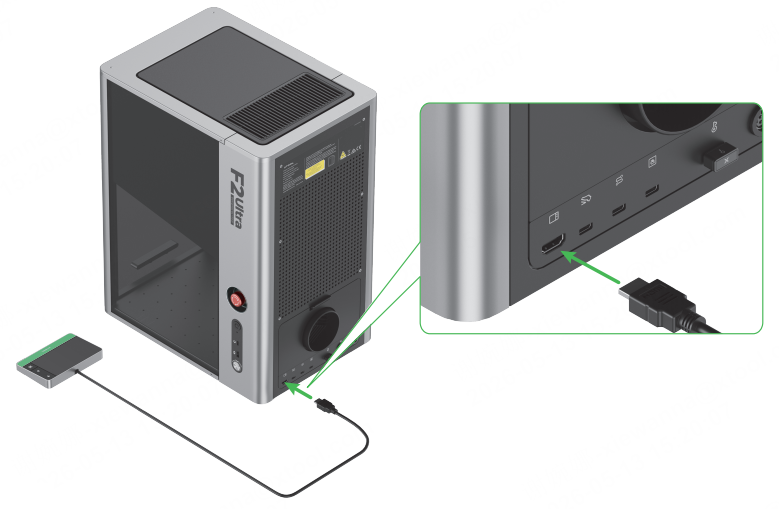
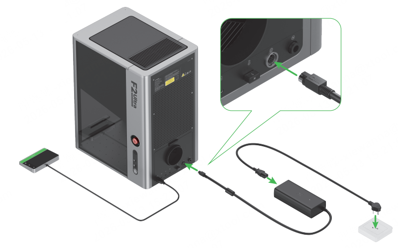
- Connect to a power supply.
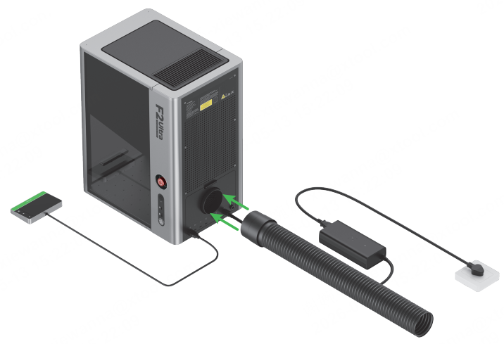
- Install the pipe.
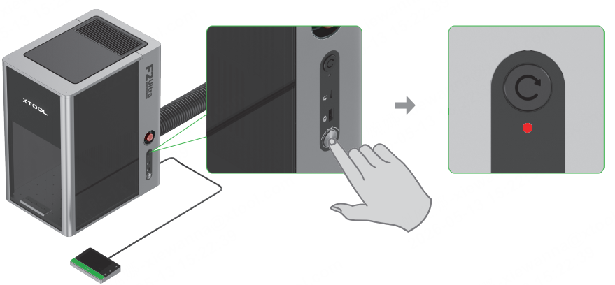
- Press the power button to turn on xTool F2 Ultra. The safety indicator will light up red.
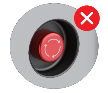
Caution: Never use the emergency stop button as a power button.
Use the emergency stop button only when an emergency occurs. Using it as a power button to turn on and off the device may damage it.
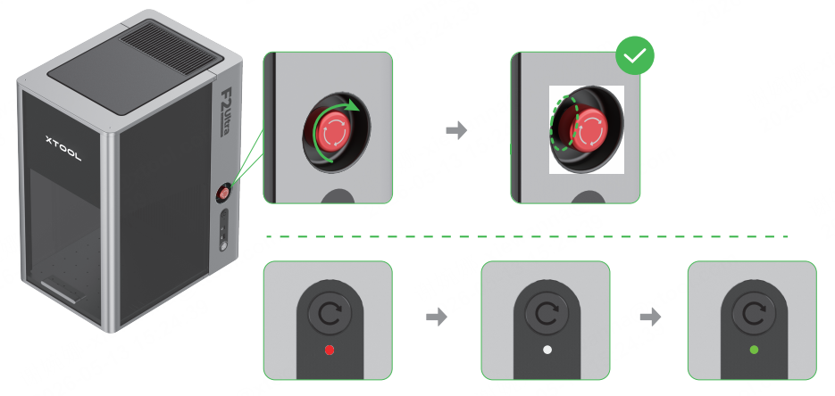
- Rotate the emergency stop button clockwise to release it. The safety indicator will first turn white and then green.
Emergency stop button
If an emergency occurs, press the emergency stop button to shut off the device.
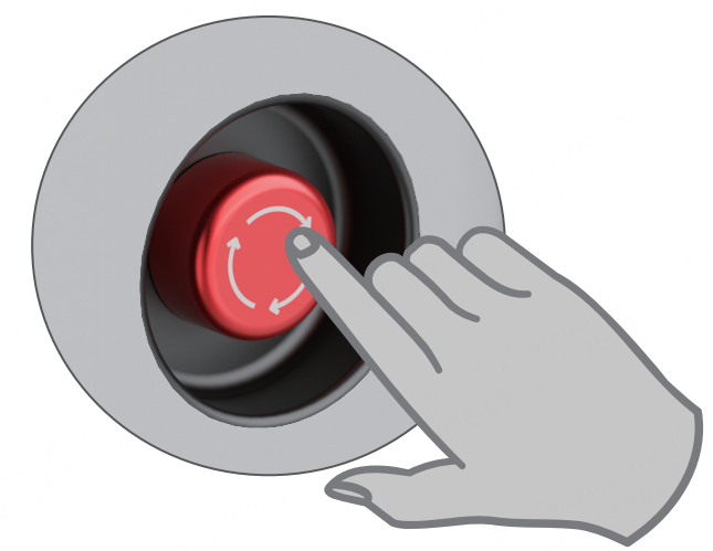
After dealing with the emergency, rotate the emergency stop button to release it.
Note: If the safety indicator does not change from white to green automatically, the device is in the safety mode. Please visit The Safety Mode (EU & UK) and follow the instructions to continue.
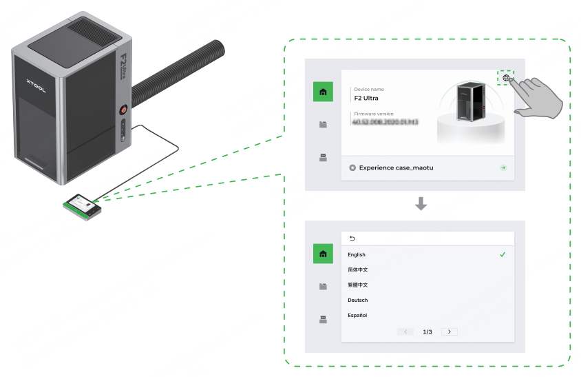
- Set the UI language of the touchscreen controller.
Use xTool F2 Ultra
- Visit s.xtool.com/software to download and install the software developed by xTool.
- Use the USB cable to connect xTool F2 Ultra to your computer, and then connect xTool F2 Ultra in the software.
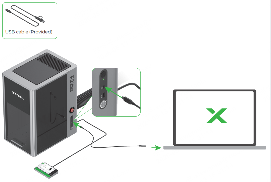
Note: The other end of the USB cable can be connected to a USB Type-A or Type-C port. Choose between the connectors based on your needs. |
For details about how to use software to operate xTool F2 Ultra to process materials, visit support.xtool.com/product/59.
Use accessories
Slatted panel
To cut a material, you are advised to use the slatted panel. It can reduce the areas burned and protect the baseplate during material processing.
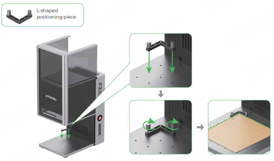
L-shaped positioning piece
You can use the L-shaped positioning piece for batch processing. It helps you place materials in the same position for each processing task.
Maintenance
Caution: Disconnect power before maintaining the product.
Clean the field lens
When laser power attenuation occurs, for example, engraved patterns are shallow or materials can't be cut as expected, the field lens may get dirty. Clean it with the lint-free cloth moistened with alcohol.
Clean the fan module
When smoke runs out of the protective enclosure, the fan module may be blocked by dust. Clean it to ensure proper smoke exhausting.
- Remove the magnetic fan guard from the smoke outlet.
- Open the cover, and then take out the fan module.
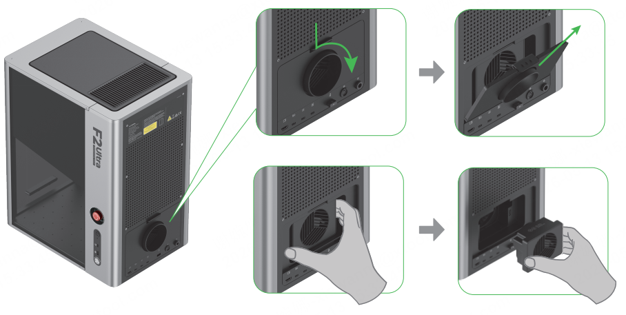
- Open the cover to reveal the fan.
- Use a brush or other tools to clean the fan module and the magnetic fan guard. Then, install them back to the main unit.
Caution: Do not rinse or immerse the fan module in water, as it may damage the circuit.