Laser embossing is to use laser beams to carve a design on the material surface. To create a raised effect, the bitmap design is first divided into multiple layers, and then the laser follows specific settings to cut the layers into different depths.
Preparations
1. Connect xTool F2 Ultra to xTool Studio
Refer to Connect and Set Up xTool F2 Ultra with xTool Studio for instructions on connecting xTool F2 Ultra to xTool Studio.
2. Prepare a design for laser embossing
To laser-emboss a material, you need to use a depth map as the processing object.
In 3D computer graphics and computer vision, a depth map is an image or image channel that contains information about the distance of objects from a specific perspective or reference point. Each pixel is assigned a value to represent the distance of that pixel from the reference point, which creates a 3D representation of the scene for its RGB image or virtual scene.
The Stanford Bunny above is a depth map. The white pixels represent the part of the scene that is closest to the reference point, and the black pixels represent the part of the scene that is furthest. In this case, the parts of the scene that are closest are the ears of the bunny. The grayscale gradient in between illustrates that the head, neck, and body are a bit further from the reference point, the legs even further, and the tail of the bunny is the furthest before the background, or the furthest point of the image. When processing, the dark color is the deep part of the engraving, and the light color is the shallow part of the engraving.
3. Obtain a depth map
You can obtain a depth map through any of the following methods.
Note: Ensure that the processing mode is set to Embossment before obtaining a depth map. (In the right panel of the page, click the name of the current processing mode, then select Embossment as the processing mode.)

Method 1: Generate a depth map with AImake
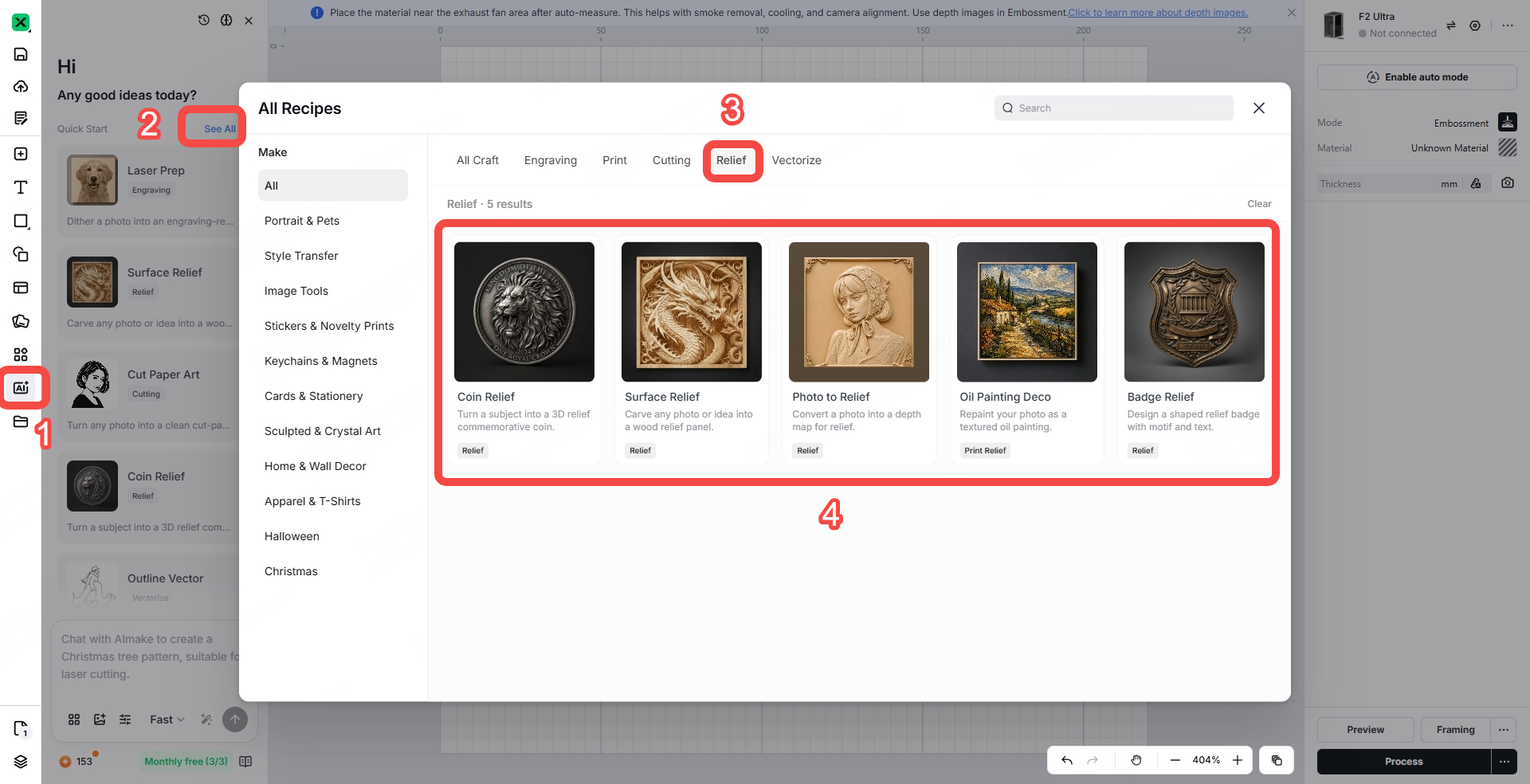
(1) In the left panel of the page, click the icon. Select See All > Relief, and then select a relief as needed.
(2) Upload an image. Then, click the up arrow to generate a depth map.

Note: To apply the generated depth map, click Export and then click Open in Studio in the Relief preview window. Close the preview window to view the depth map on the canvas.
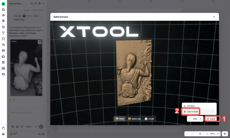
You can also hover over the generated depth map after closing the Relief preview window, and then click to import it to the canvas.

Method 2: Input text to generate a depth map
(1) In the left panel of the page, click the  icon. Enter a prompt describing the depth map you want to generate in the box in the lower left corner, and then click the up arrow.

(2) Select a drawing style or click Decide for me as needed.

(3) Click Export and then click Open in Studio.
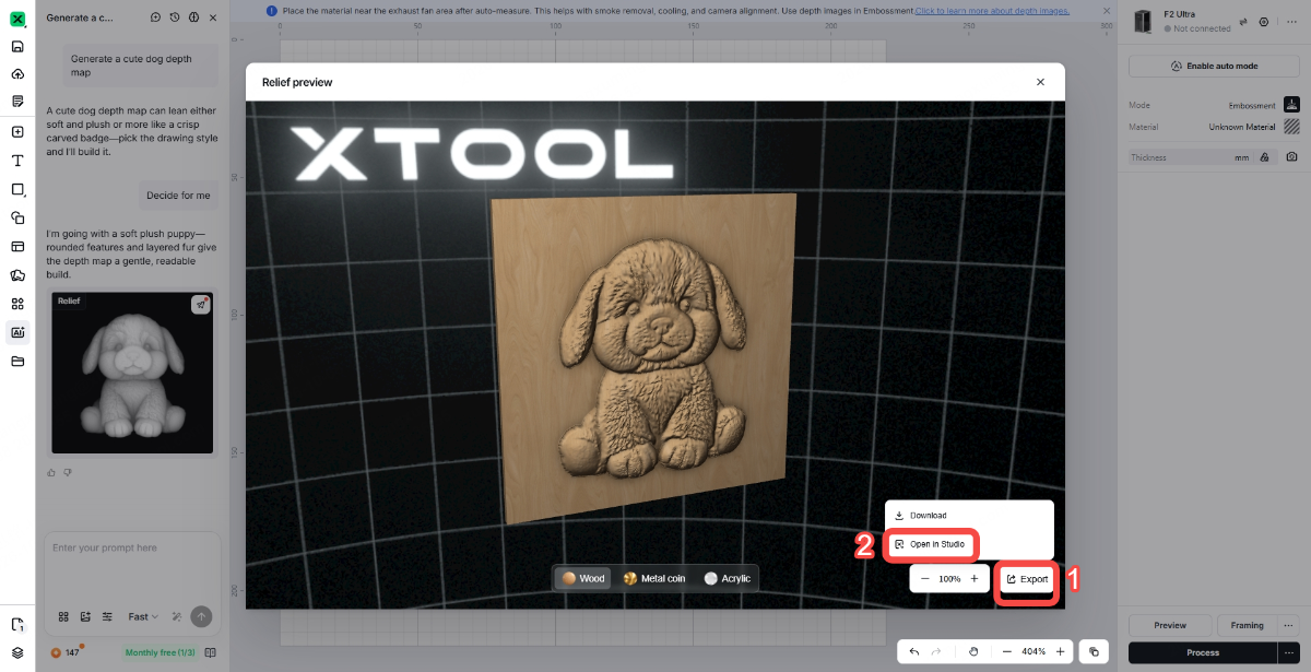
(4) Close the preview window to view the depth map on the canvas.

Method 3: Import an image to generate a depth map
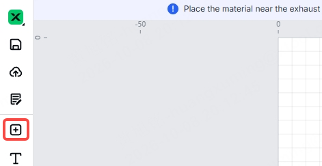
(1) Click the  icon to import an image to xTool Studio.
(2) Select the image you import, click Edit, and click AI Emboss.
Note: The AI Emboss icon is displayed only when the processing mode is set to Embossment.

(3) Click Generate Emboss.

Then you can get a depth map.

Start laser embossing
1. Select the material
Click Unknown Material, select a desired material, and click Apply.
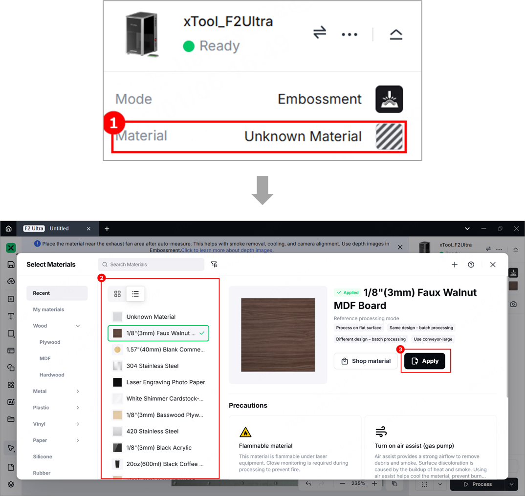
Note:
- After you select a material from the material list, the software will automatically set parameters for laser processing. Default settings are available for xTool materials. You can adjust the settings as required.
- The recommended parameter settings can achieve the best results only when using xTool's materials. If you are using materials from third parties, it is recommended that you conduct a material test array on your own first to obtain the desired effects and parameters. Meanwhile, make sure that the materials are free from moisture or contamination, which may greatly affect the results.
2. Place the material and perform laser focusing
(1) Lift the protective enclosure, and place the material on the baseplate, allowing the blue light spot to fall on the surface of the material.
(2) Hold down on the Up/Down button to lift or lower the laser module. When the red and blue light spots overlap, the focus is successfully set.
Note: The blue light spot does not move. If the laser module moves up, the red light spot moves towards the left. If the laser module moves down, the red light spot moves towards the right.
(3) After finishing focusing, the measured material thickness can be seen in the top-right corner.
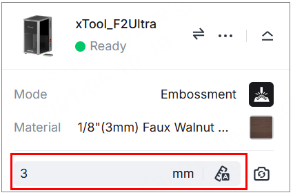
Note: xTool F2 Ultra supports auto-focus and manual focus. Here we use manual focus. For more information on how to use auto-focus, see Perform Laser Focusing.
3. Shoot background and import a depth map
(1) On the right side, click the iconto refresh the background.
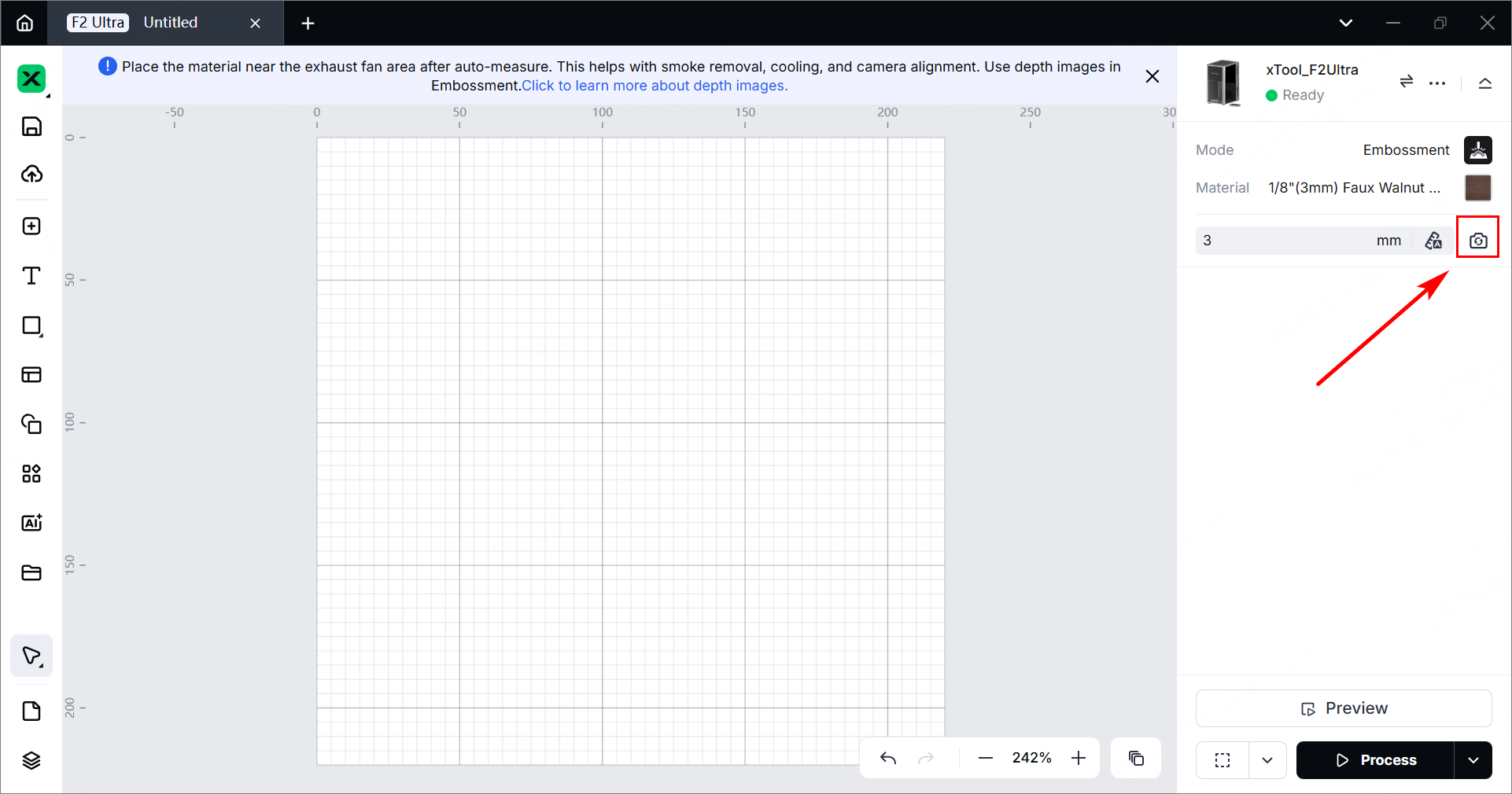
Note:
- To ensure positioning accuracy, set the laser focus before shooting the background.
- Ensure that the background photo can fully and clearly display the material. You can adjust the shooting environment by adjusting the device's fill light or pulling down the protective enclosure.
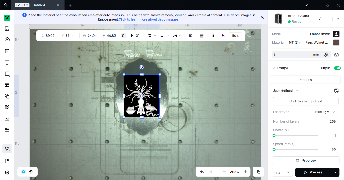
(2) Use the methods described in obtain a depth map to import a depth map.
For example, on the left side, click > Embossment > select a depth map to import it.
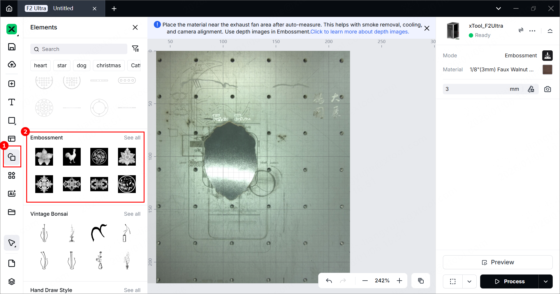
(3) Drag the anchor points of the bounding box to resize the image, and drag the image to move it.
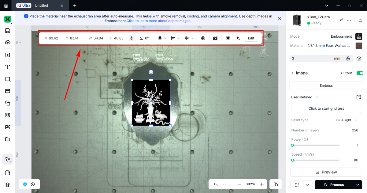
(4) Use the tools above the canvas for further editing.
4. Set processing parameters
Select objects on the canvas. In the right panel of the page, set parameters for the selected objects.
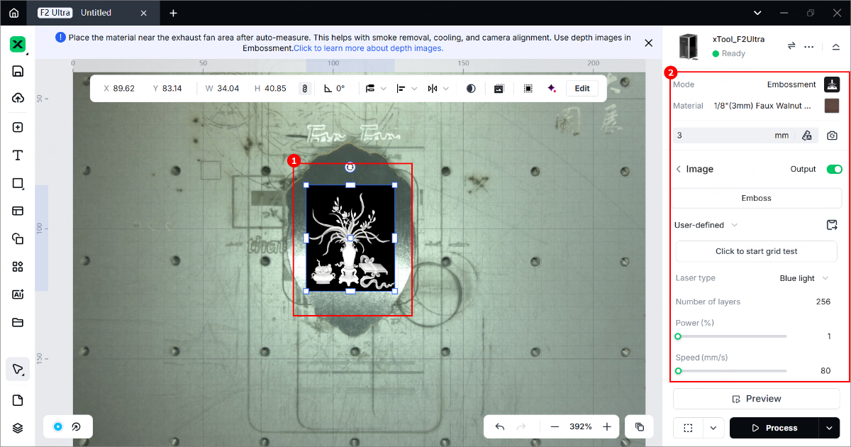
- Laser type
Blue light is typically used with materials like Tilia wood, corrugated paper, and leather, and for laser cutting.
Fiber IR is ideal for engraving metals such as stainless steel, gold, silver, copper, aluminum, etc. - Number of layers
The more layers you set, the deeper the laser carves into the material surface. Valid value: [1, 256], integer. - Power (%)
The power of the laser. The higher the power, the deeper the laser carves into the material surface. Valid value: [1, 100], integer. - Speed (mm/s)
The moving speed of the laser dots along the processing path. If the laser dots move more slowly, the processing time will be longer, and the material will absorb more energy. Therefore, the smaller the speed, the deeper the laser carves into the material surface. - Pass
The number of times the laser dots pass over the processing path. The more passes, the deeper the laser carves into the material surface. Valid value: [1, 10], integer. - Lines per cm
The number of lines engraved within each centimeter. It affects the resolution of the embossing result. - Engraving angle
The angle of the laser beams when engraving on the material. This angle is a relative angle between the laser beams and the processing points. For normal operation, it is recommended to set the value to 30. - Descend at the z-axis
As the laser carves deeper into the material, the laser beam may be out of focus. By turning on this feature, the laser module will descend at the z-axis, so that the laser beam can keep focusing on the material surface. A focused laser beam produces the highest energy.
For materials such as brass that require high laser power, you are advised to turn on Descend at the z-axis for better processing results. In other conditions, if not necessary, you are not advised to turn on this feature.
Note: For more information about the processing parameters, see Processing Parameters for xTool F2 Ultra (Single-Laser Model) or Processing Parameters for xTool F2 Ultra (Dual-Laser Model).
5. Set the processing path
(1) In the bottom-right corner, click the icon to set the processing path.
(2) Turn on or off the Evade smoke mode. When this feature is enabled, the device follows a path less affected by the smoke to process the material.
Note: It is recommended to enable this feature for scoring on materials such as wood and corrugated paper that produce heavy smoke. Otherwise, the heavy smoke may block the laser beams and interfere laser processing.
(3) Set the Processing path.
- Auto planning: xTool Studio automatically plans the processing path based on intelligent algorithms.
- User defining: Manually set the processing paths for objects.
6. Preview the processing area
(1) In the bottom-right corner of the software, click the icon to set parameters for framing.
In Rect mode, the laser dots move along the rectangular boundary of the objects to be processed. In Outline mode, the laser dots move along the outlines of the objects to be processed. In Polygon mode, the laser dots move along the polygonal path defined by the vertices of the objects to be processed.
(2) Click the icon in the software. The laser dots will move along the boundary of the processing objects on the material, allowing you to preview the processing area.
To stop framing, click the same button.
7. Start processing
(1) In the bottom-right corner of the software, click Process.
(2) Preview the processing design.
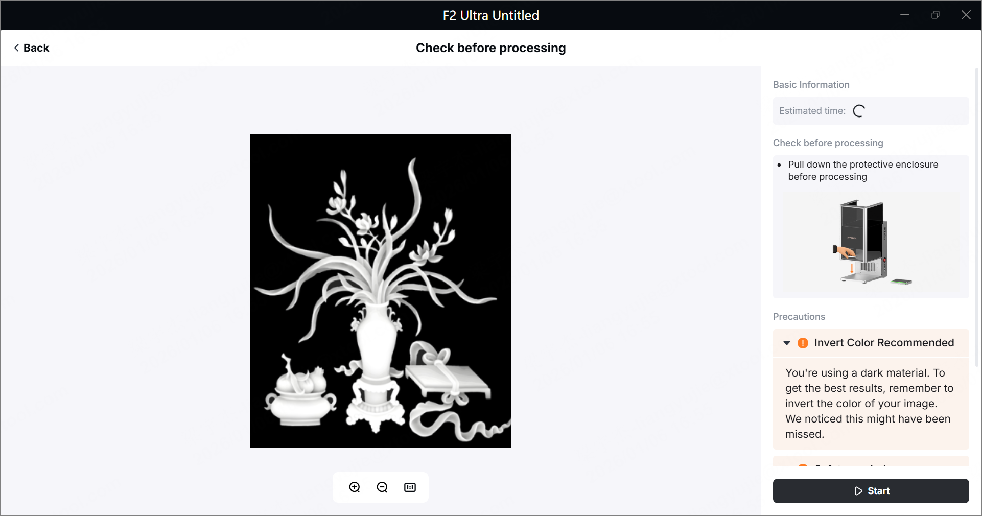
(3) Close the protective enclosure. In the bottom right corner, click Start.
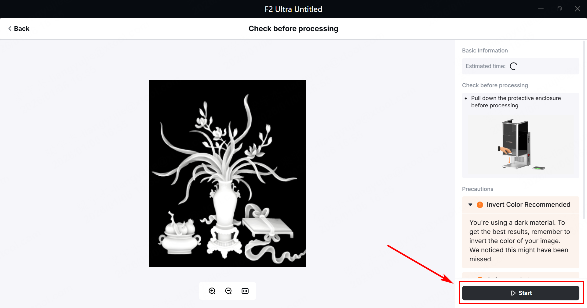
(4) When the software shows Ready, press the XTOOL Start/Stop button on the touchscreen controller to start processing.
⚠️Safety Reminder: During laser processing, keep the protective enclosure closed or wear a pair of goggles that can shield laser beams of 445 ± 15 nm and 1064 ± 5 nm wavelengths.
More information
xTool F2 Ultra Example Project
(xTool Studio) Process on Flat Surface with xTool F2 Ultra
(xTool Studio) Process a Curved Material with xTool F2 Ultra
(xTool Studio) Start Color Engraving with xTool F2 Ultra
(xTool Studio)Start Offline Processing with the Touchscreen Controller
(xTool Studio) Use the Conveyor to Process a Large Material with xTool F2 Ultra
(xTool Studio) Use the Conveyor for Same Design Batch Processing with xTool F2 Ultra
(xTool Studio) Use the Conveyor for Different Design Batch Processing with xTool F2 Ultra
(xTool Studio) Use Rotary Attachment 3 (RA3) with xTool F2 Ultra
Use xTool F1 Ultra / F2 Ultra Series to Engrave a Screen in xTool Studio