Laser Type
xTool F2 Ultra supports two types of laser for processing: blue-light laser (40 W) and MOPA infrared laser (60 W). You need to choose the proper laser type based on the material to be processed.
🔵 Blue light is typically used with materials like Tilia wood, corrugated paper, and leather, and for laser cutting.
🔴 MOPA IR (infrared) is ideal for engraving metals such as stainless steel, gold, silver, copper, aluminum, etc.
- Test Matrix File
To experience the actual differences in processing results, you can download the test matrix file below.
Please use the following material for processing: MOPA IR (infrared) – Stainless Steel Sheet.
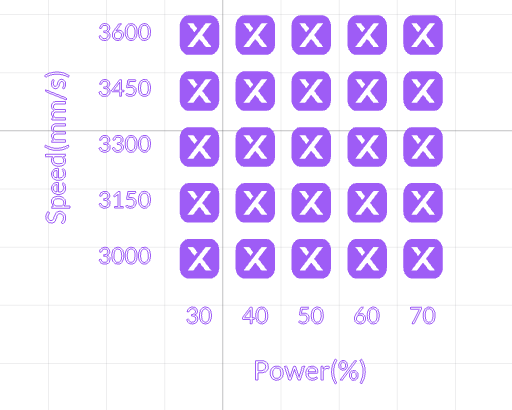 | 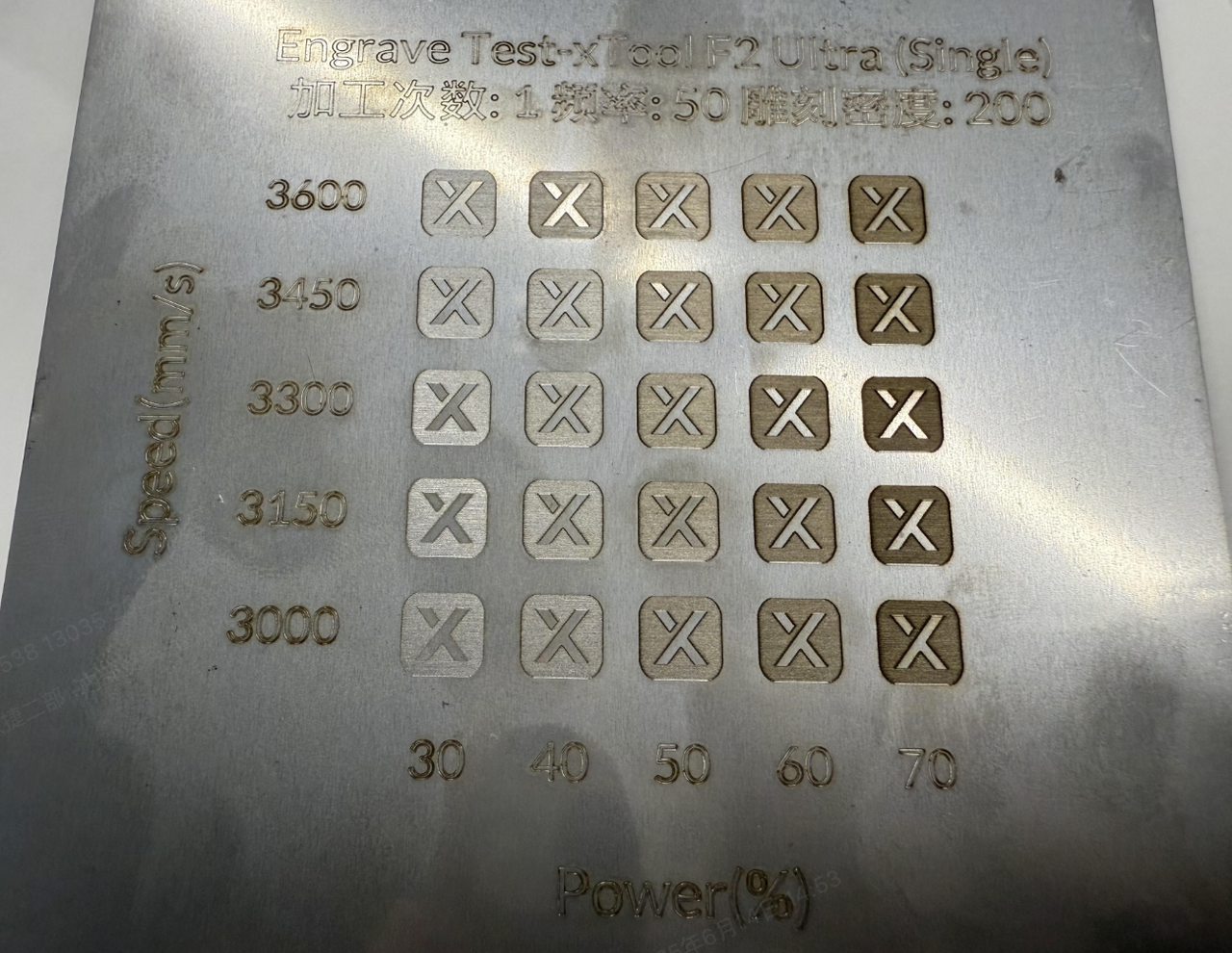 |
Test matrix | Example |
Please use the following material for processing: Blue Laser – Basswood Board.
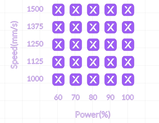 | 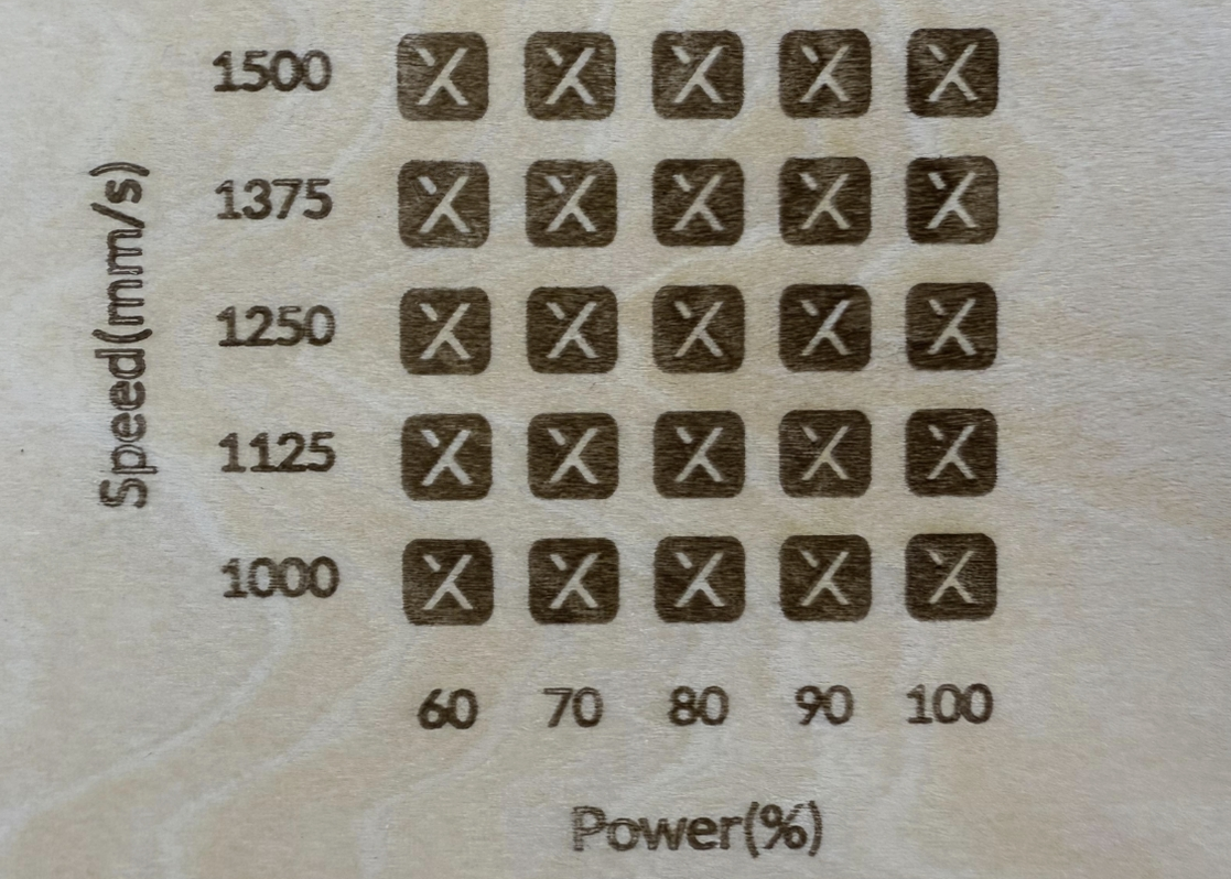 |
Test matrix | Example |
Power
The laser power determines the energy density and processing capability of the laser. Different power levels can produce varying engraving depths. High power combined with low speed can achieve cutting effects.
- Test Matrix File
To experience the actual processing results, you can download the test matrix file below.
Please use the following material for processing: MOPA IR (infrared) – Stainless Steel
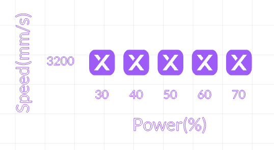 | 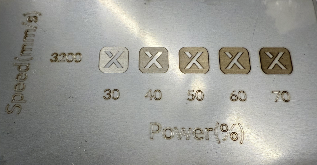 |
Test matrix | Example |
Speed
The moving speed of the laser beam. If the laser beam moves slower, the processing time will be longer and the material will absorb more energy. Therefore, the smaller the speed, the deeper the laser carves into the material surface.
- Test Matrix File
To experience the actual processing results, you can download the test matrix file below.
Please use the following material for processing: MOPA IR (infrared) – Stainless Steel
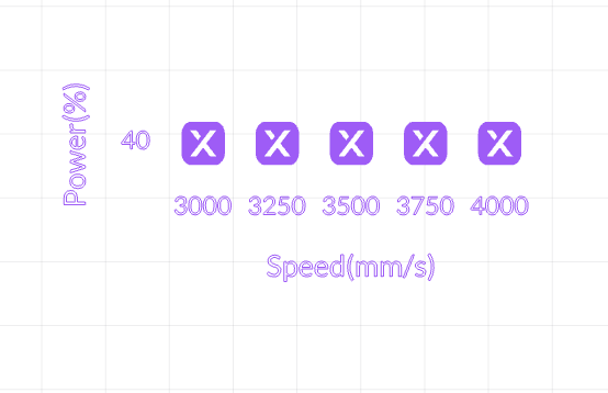 | 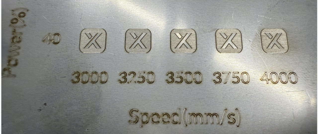 |
Test matrix | Example |
Dot Duration
When processing bitmap, a complete image is formed by methodically doting each point. Hence the term "Dot Duration" refers to the time spent at each point, measured in microseconds (μs), and it affects the overall processing time. Different dwell time produces different depths of engraving marks.
To ensure stable light output, especially for infrared lasers, we recommend setting more than 100μs. The optimal timing varies with the material but usually falls between 100 and 500. Please note that excessive dot duration could result in a whitening effect and a longer processing time.
- Test Matrix File
To experience the actual processing results, you can download the test matrix file below.
Please use the following material for processing: MOPA IR (infrared) – Stainless Steel
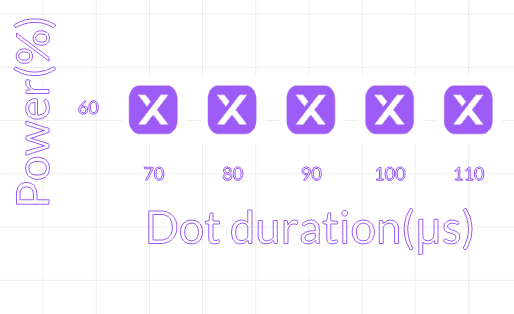 | 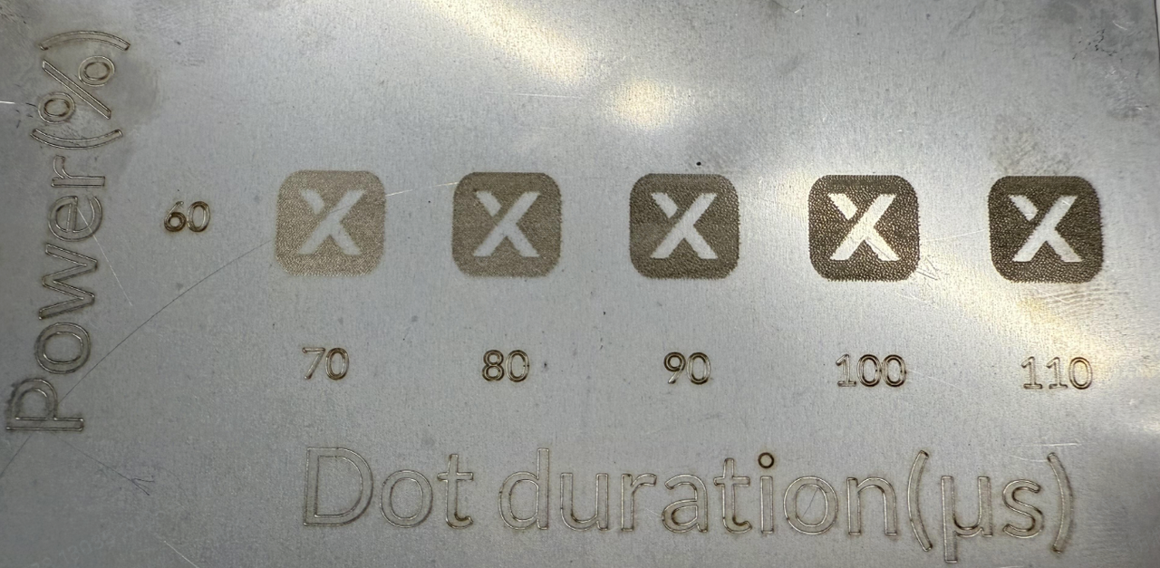 |
Test matrix | Example |
Line per cm
The number of linear engraving lines within the target processing area. Higher density means smaller line spacing, finer patterns, and longer processing time. The number of lines engraved within each centimeter.
- Test Matrix File
To experience the actual processing results, you can download the test matrix file below.
Please use the following material for processing: MOPA IR (infrared) – Stainless Steel
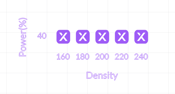 | 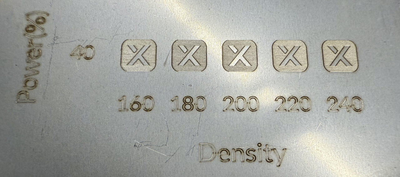 |
Test matrix | Example |
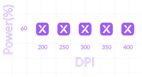
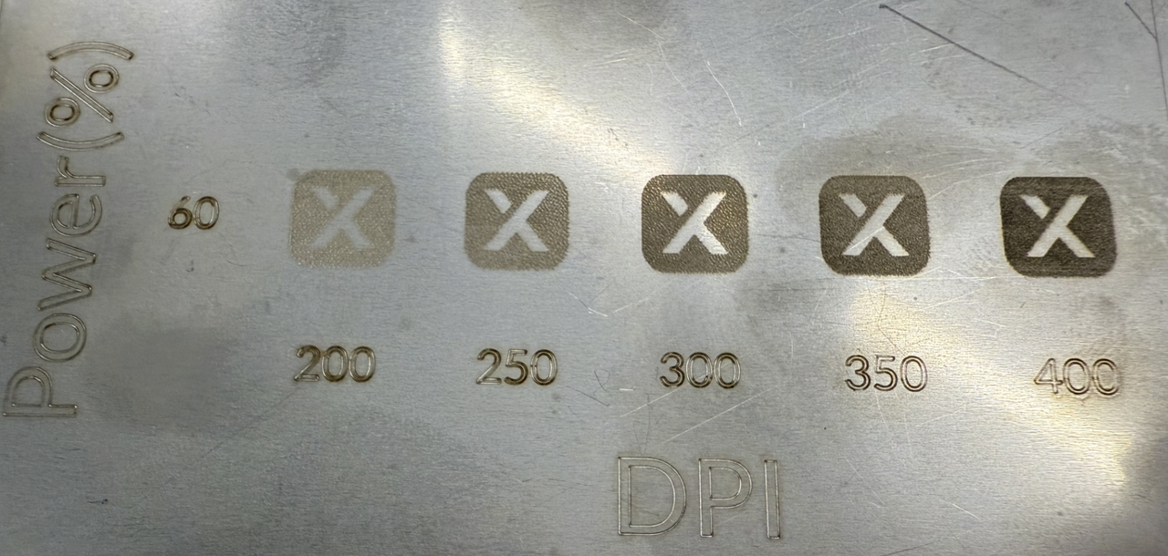
DPI
DPI is a unit of measurement in dot matrix digital image, indicating the number of image pixels per inch. The setting range is [1, 1270]. When converted into linear density (lines per cm), 100 linear density equals 254 DPI.
A higher DPI theoretically yields a finer engraving image effect. However, when the DPI surpasses the bitmap's pixel distribution, overly dense dots can have a counterproductive effect, causing darker materials to appear whiter (shown in the image below).
- Test Matrix File
To experience the actual processing results, you can download the test matrix file below.
Please use the following material for processing: MOPA IR (infrared) – Stainless Steel
 |  |
Test matrix | Example |
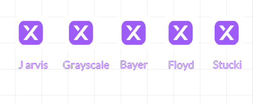
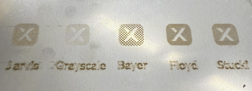
Bitmap mode
Software provides multiple bitmap modes for selection, catering to most bitmap usage scenes. You can choose the type that best suits your image. Generally, we recommend Jarvis mode for infrared light and grayscale mode for blue light.
With the other settings unchanged, the output of an image on a wooden board varies according to image mode, as shown in the following figure.
- Test Matrix File
To experience the actual processing results, you can download the test matrix file below.
Please use the following material for processing: MOPA IR (infrared) – Stainless Steel
 |  |
Test matrix | Example |
Pulse Width and Frequency
MOPA infrared lasers support adjustable pulse width and frequency. So what’s the purpose of adjusting these two parameters?
- Adjusting Frequency: When other parameters remain constant, lowering the frequency increases both the peak power and the energy of a single pulse.
- Adjusting Pulse Width: When other parameters remain constant, increasing the pulse width will decrease the peak power of a single pulse, while the pulse energy remains constant.
- Higher single-pulse energy means stronger material removal capability, suitable for scenarios like metal cutting and rust removal.
- Higher peak power enables higher precision and less thermal impact, making it ideal for fine engraving.
Why does xTool distinguish between different pulse width/frequency levels, while other brands do not?
- Reason:
The laser gain medium needs a recovery period. Under short pulse widths and high repetition rates, the interval between pulses is much shorter than the energy storage time of the gain medium, allowing continuous energy extraction — thus enabling high-frequency output.
In contrast, long pulse widths require more time to release energy per pulse, so the gain medium needs more time to recharge. If the frequency is too high, it may lead to insufficient energy storage and unstable output. - Benefits:
- Gain Medium Energy Management: Short pulse width at high frequency allows quick energy recovery, avoiding power fluctuations. Long pulse width requires energy storage time to ensure output stability. xTool’s pulse-frequency matching ensures a precise balance between energy release and medium recovery, guaranteeing long-term stable output.
- User-Friendliness: Prevents invalid parameter combinations and reduces the risk of hardware damage (e.g., pump source overload) due to exceeding operational limits.
How to choose the right combination?
- If you want sharper and more delicate engraving, use:
→ Short pulse width + low frequency + medium-to-low power - If you want fast material removal, use:
→ Long pulse width + low frequency + high power
Wobble
This feature enhances cutting capability through a spiral processing path, but it will significantly increase processing time. The specific path is shown in the diagram below:
How to Set Wobble Parameters
- The spacing should be smaller than the diameter. You can refer to the following formula: Spacing = Diameter × (0.3 to 0.5)
- Fine cutting: 0.3–0.4 × diameter
- Fast cutting: 0.4–0.5 × diameter
- Thick material cutting: 0.25–0.35 × diameter
- Thin materials:
- Diameter: 0.1–0.2 mm
- Spacing: 0.03–0.06 mm
- Medium-thickness materials:
- Diameter: 0.2–0.3 mm
- Spacing: 0.06–0.09 mm
- Thick materials:
- Diameter: 0.3–0.5 mm
- Spacing: 0.09–0.15 mm
