Requirements on materials
- Use a material with a smooth surface and gentle curves that meet the requirements below.
- The angle between the tangent to the curve at any point and a horizontal line should be no more than 45 degrees.
- The distance between the highest and lowest points on the curved surface should be no more than 10 cm.
- Abrupt height change, sharp corners, and inward sloping are not supported.
Note: Do not use highly reflective materials. xTool F2 Ultra measures curved surfaces based on optical principles. Excessive reflections from the material may cause inaccurate measurements.
Connect xTool F2 Ultra to xTool Studio
Refer to Connect and Set Up xTool F2 Ultra with xTool Studio for instructions on connecting xTool F2 Ultra to xTool Studio.
Start processing with xTool Studio
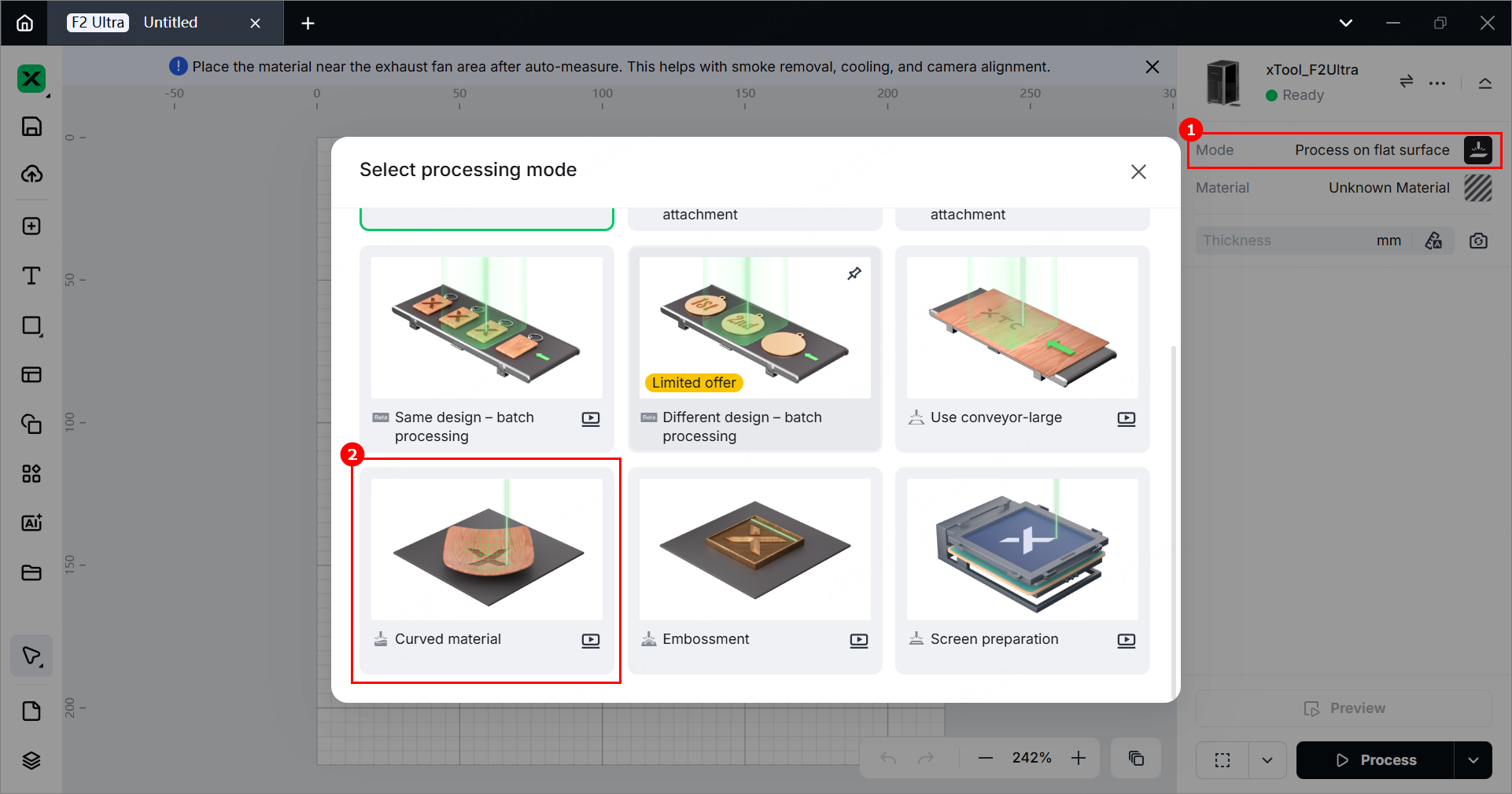
1. Select the processing mode
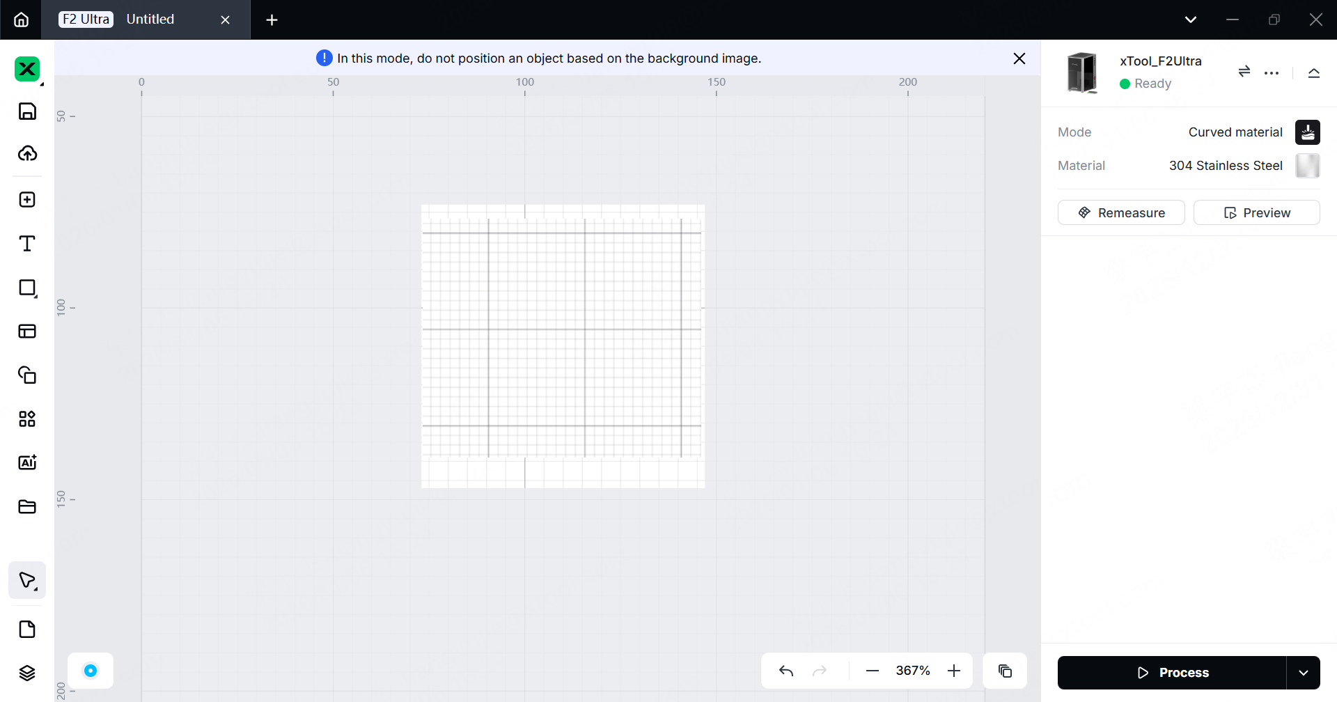
(1) In the right panel of the page, click the name of the current processing mode, then select Curved material.
(2) Click Unknown Material, select a desired material, and click Apply.
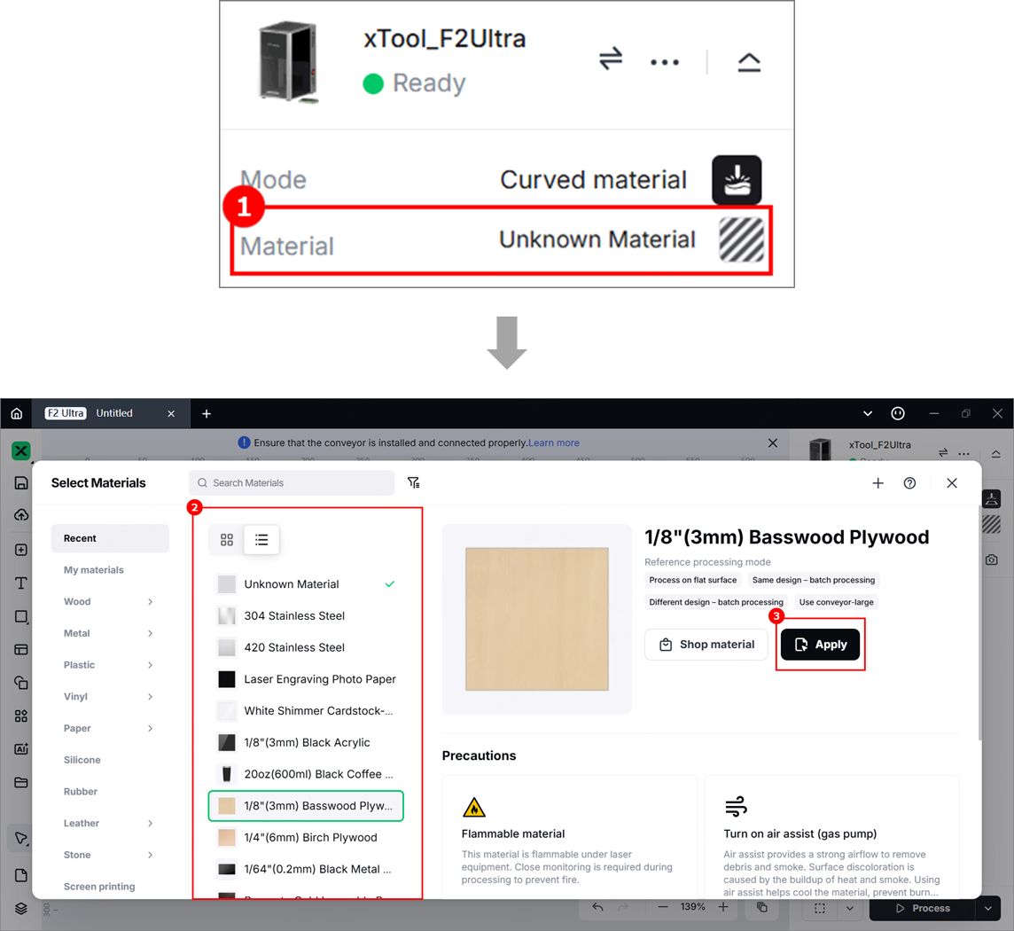
Note:
- After you select a material from the material list, the software will automatically set parameters for laser processing. Default settings are available for xTool materials. You can adjust the settings as required.
- The recommended parameter settings can achieve the best results only when using xTool's materials. If you are using materials from third parties, it is recommended that you conduct a material test array on your own first to obtain the desired effects and parameters. Meanwhile, make sure that the materials are free from moisture or contamination, which may greatly affect the results.
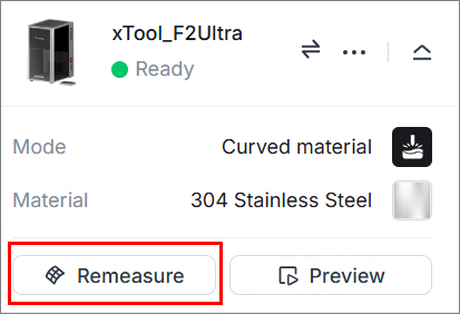
2. Set the laser focus
(1) In the right side of the page, click the Remeasure icon.
(2) Lift the protective enclosure, and place the material on the flat surface, allowing the blue light spot to fall in the center of the desired processing area.
(3) Hold down on the Up/Down button to lift or lower the laser module. When the red and blue light spots overlap, the focus is successfully set.
Note: The blue light spot does not move. If the laser module moves up, the red light spot moves towards the left. If the laser module moves down, the red light spot moves towards the right.
3. Select the processing area
(1) On xTool Studio, click Framing, and then you can see a blue rectangular projection, which indicates the target processing area.
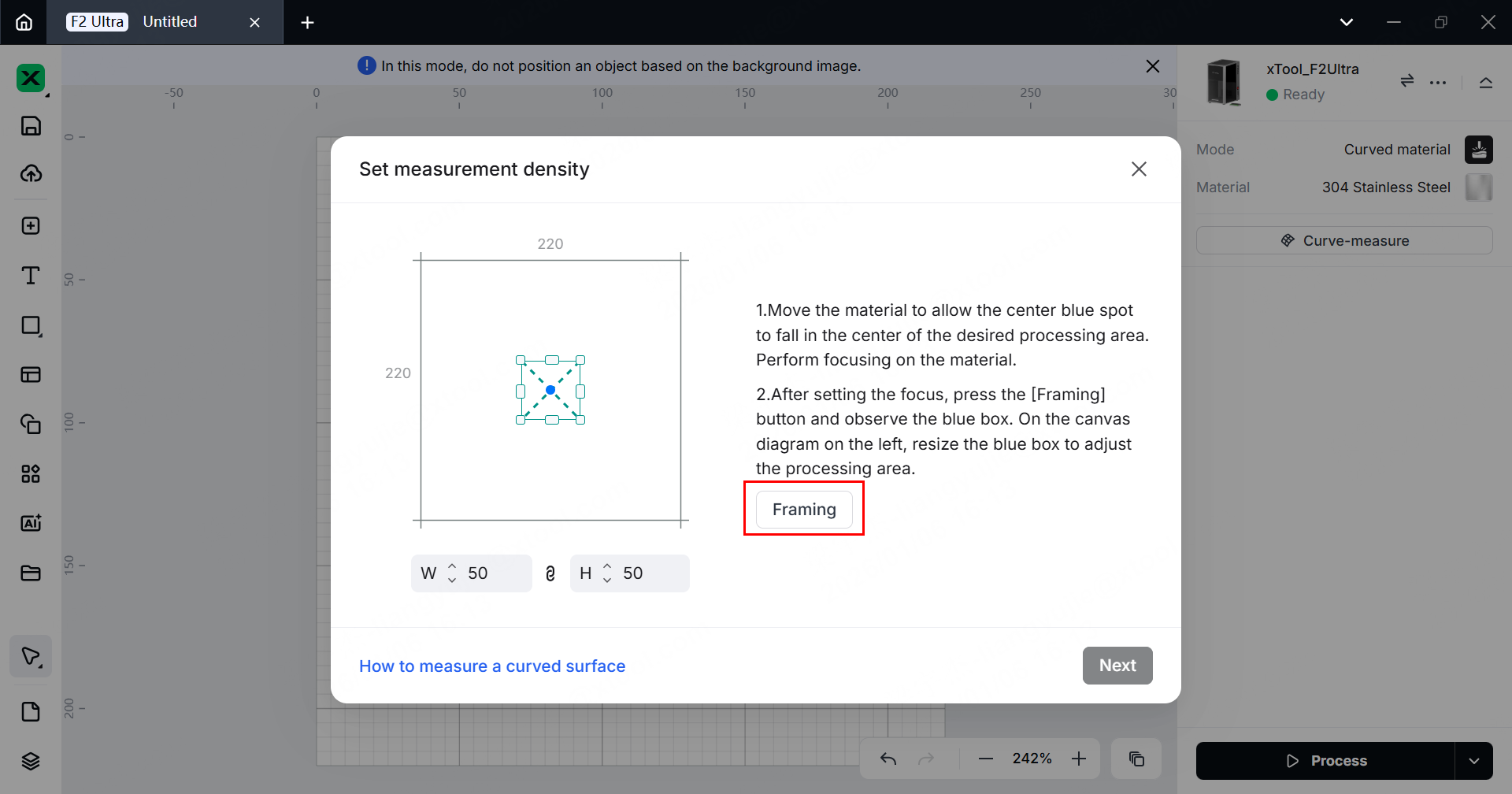
(2) Drag the handles to resize the bounding box, so as to adjust the target processing area. After confirming, click Next.
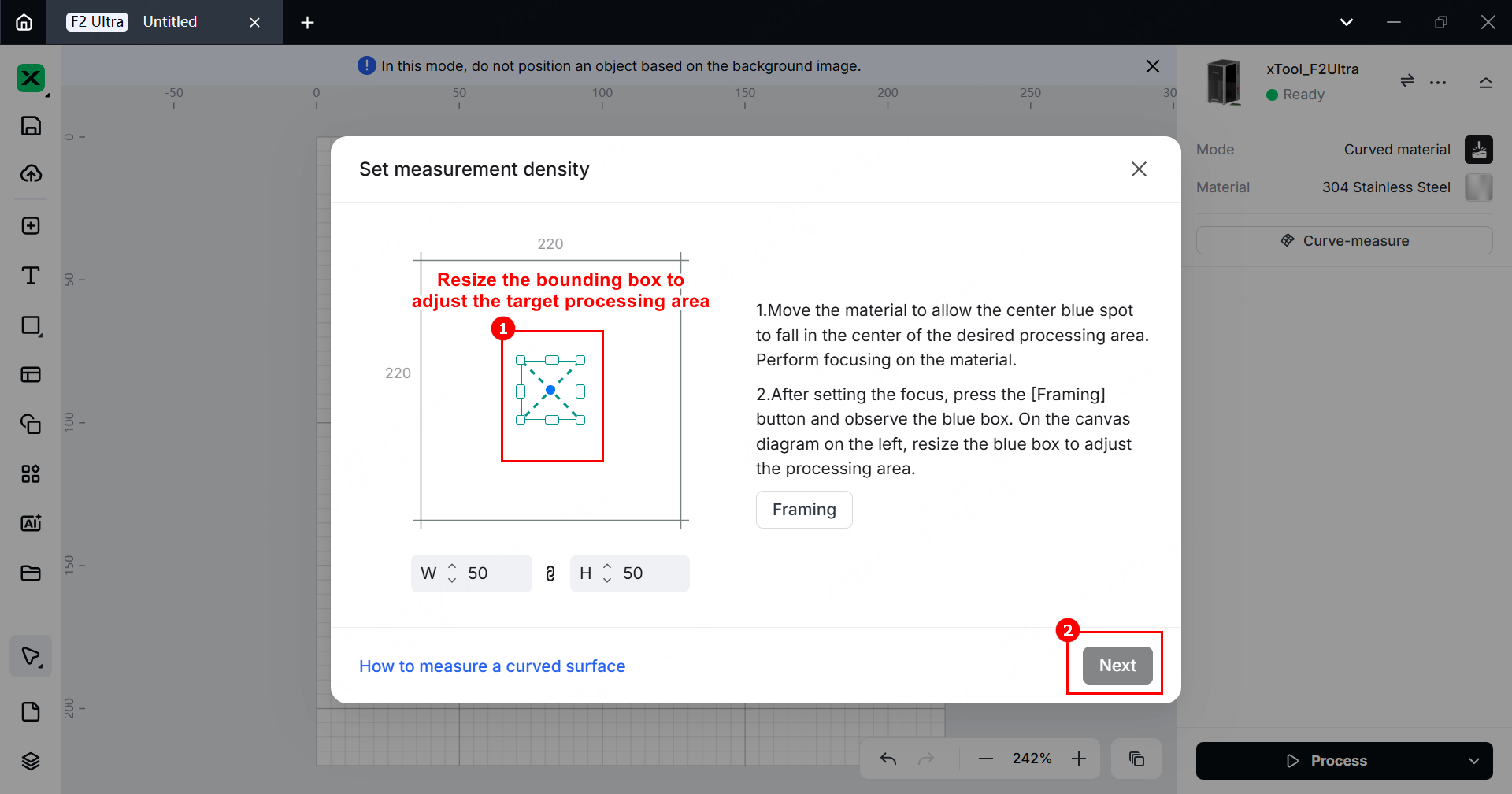
Note: By default, the width and height proportion is locked. You can unlock it by clicking the  icon.
icon.
4. Set the measurement density
(1) xTool Studio provides recommended measurement density based on the size of the selected area. You can adjust the measurement density by changing the Rows and Columns.
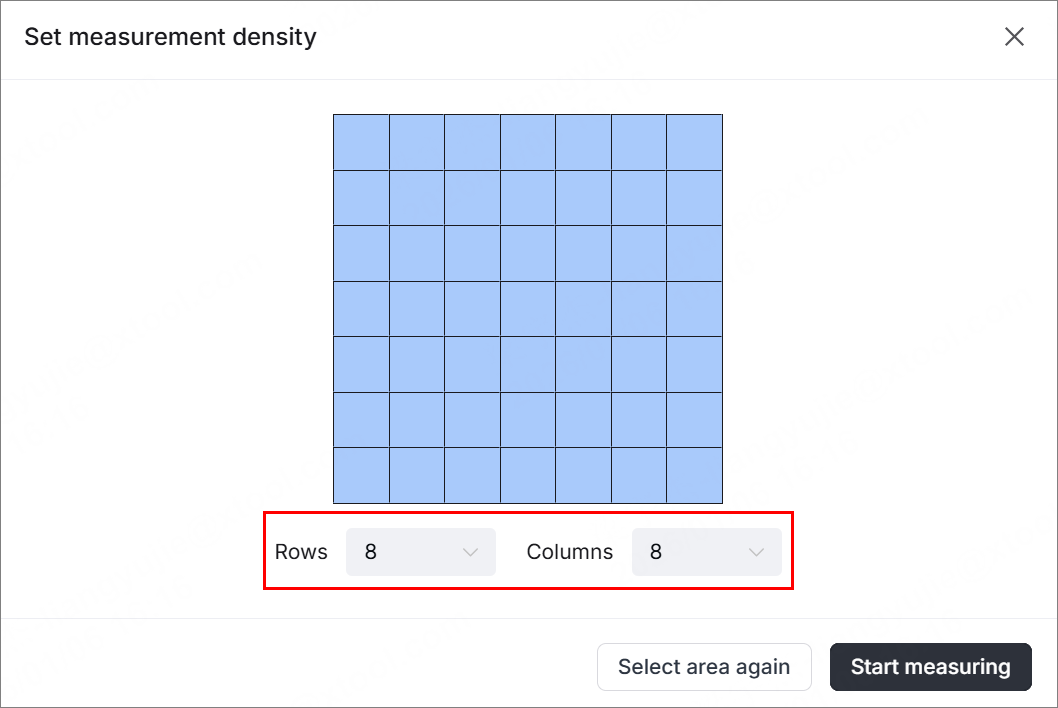
Note: The more rows and columns, the higher the measurement density, the more precise the model, but the longer the measurement time.
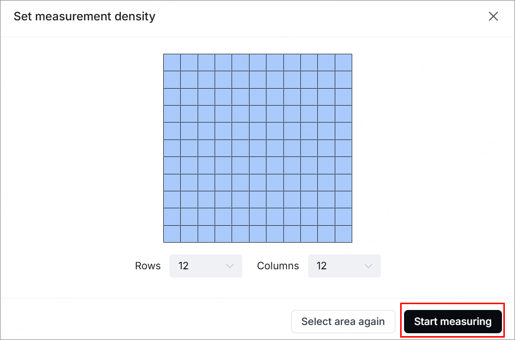
(2) Click Start measuring, and the device will measure the height of each point on the selected area. You can see the measurement progress on xTool Studio.
(3) After completing the measurement, xTool Studio generates a 3D model.
- To rotate the model, drag it with the mouse.
- To adjust the model, change the Smoothness and Tension.
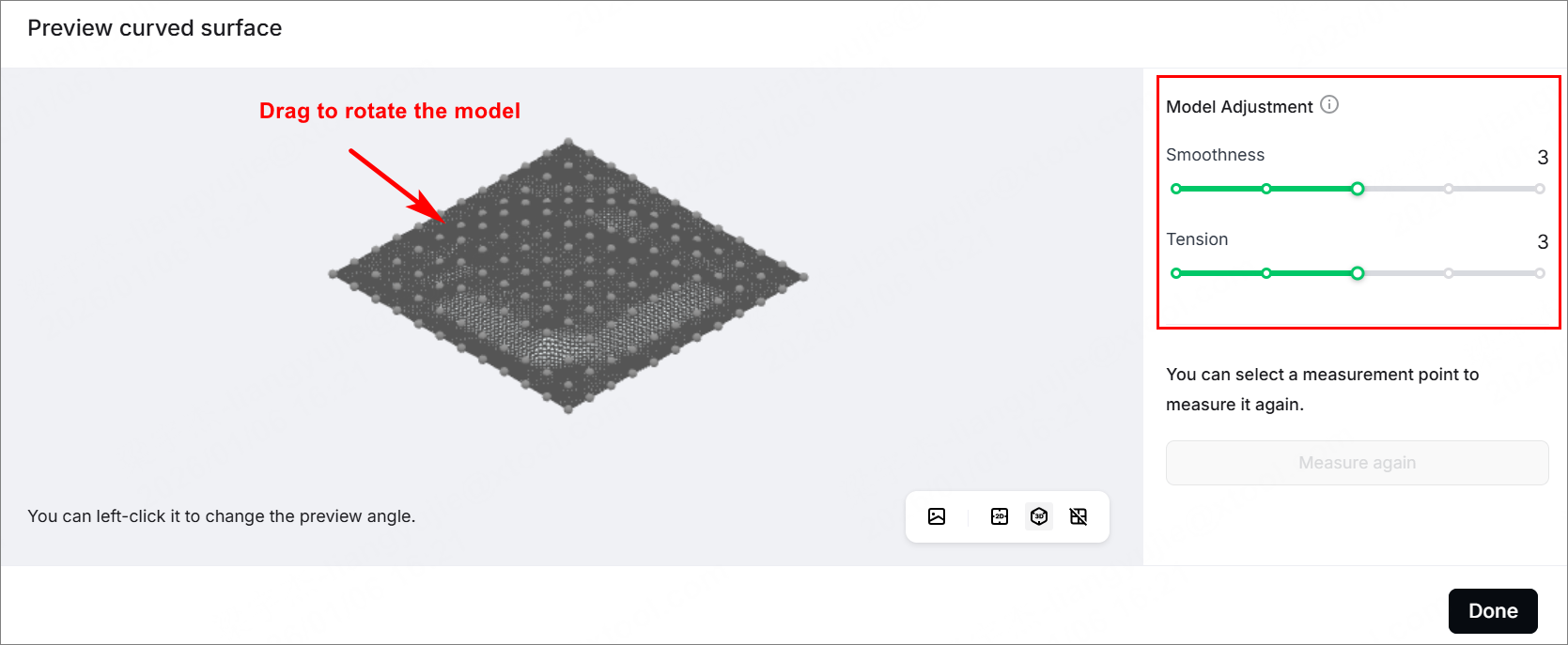
(4) Click Done. The selected and measured area is displayed normally on the canvas, while the other area becomes grey, which indicates a non-processing area.
5. Design objects and set processing parameters
Note: The gray area on the canvas is unmeasured. Do not place objects in this area.
(1) Use the tools to the left of the canvas to create objects on the canvas. You can import images, insert shapes, enter text, draw vector graphics, and so on.
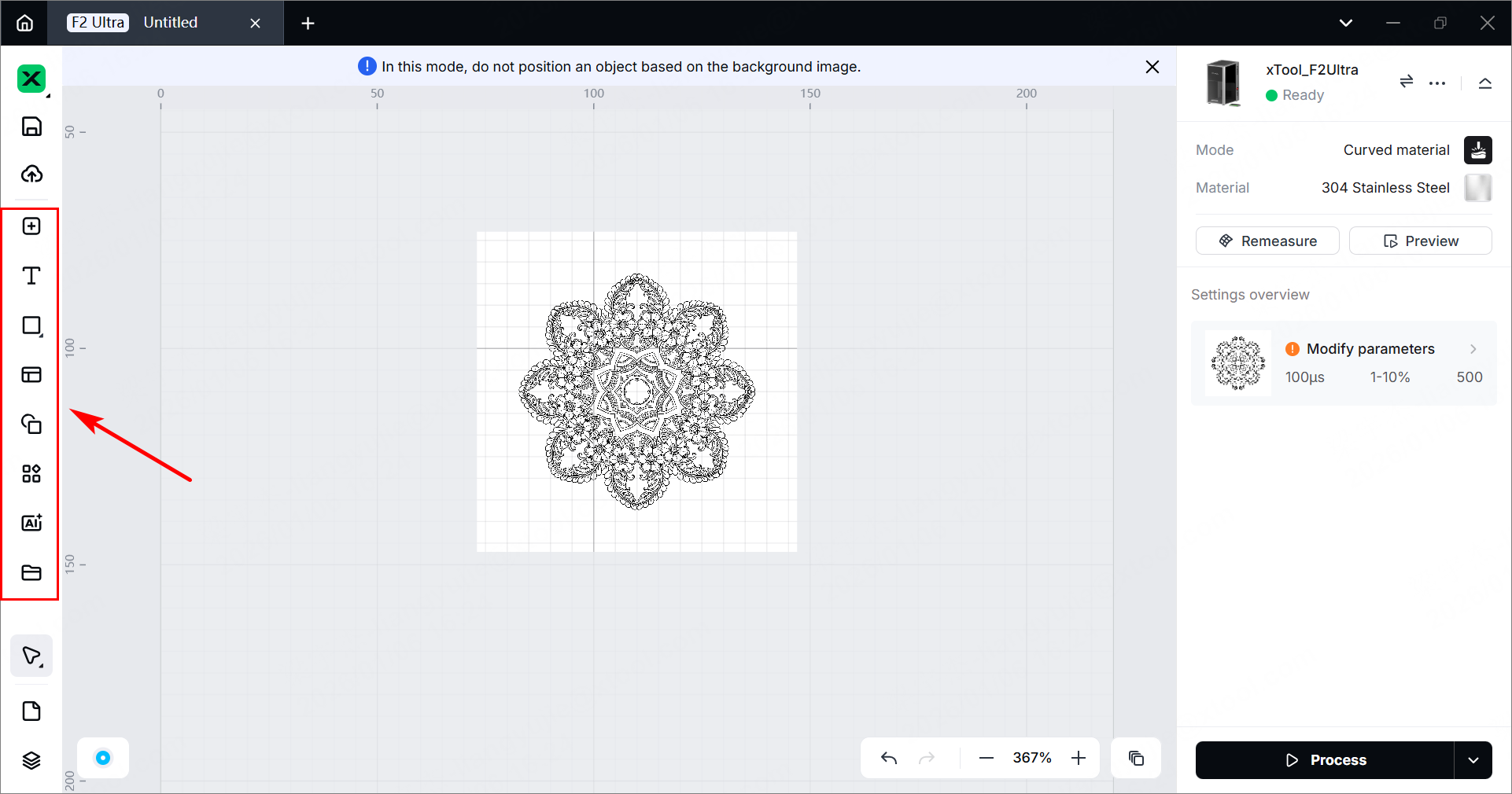
Note: For more information on how to use xTool Studio to design objects, see Software Learning Center.
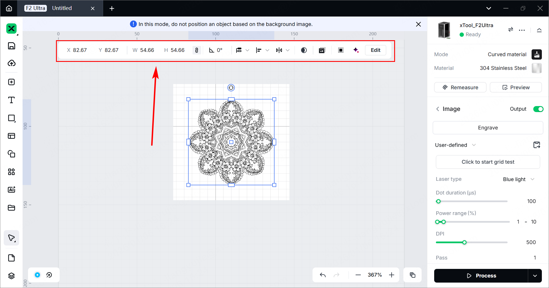
(2) After selecting the objects, use the tools above the canvas for further editing.
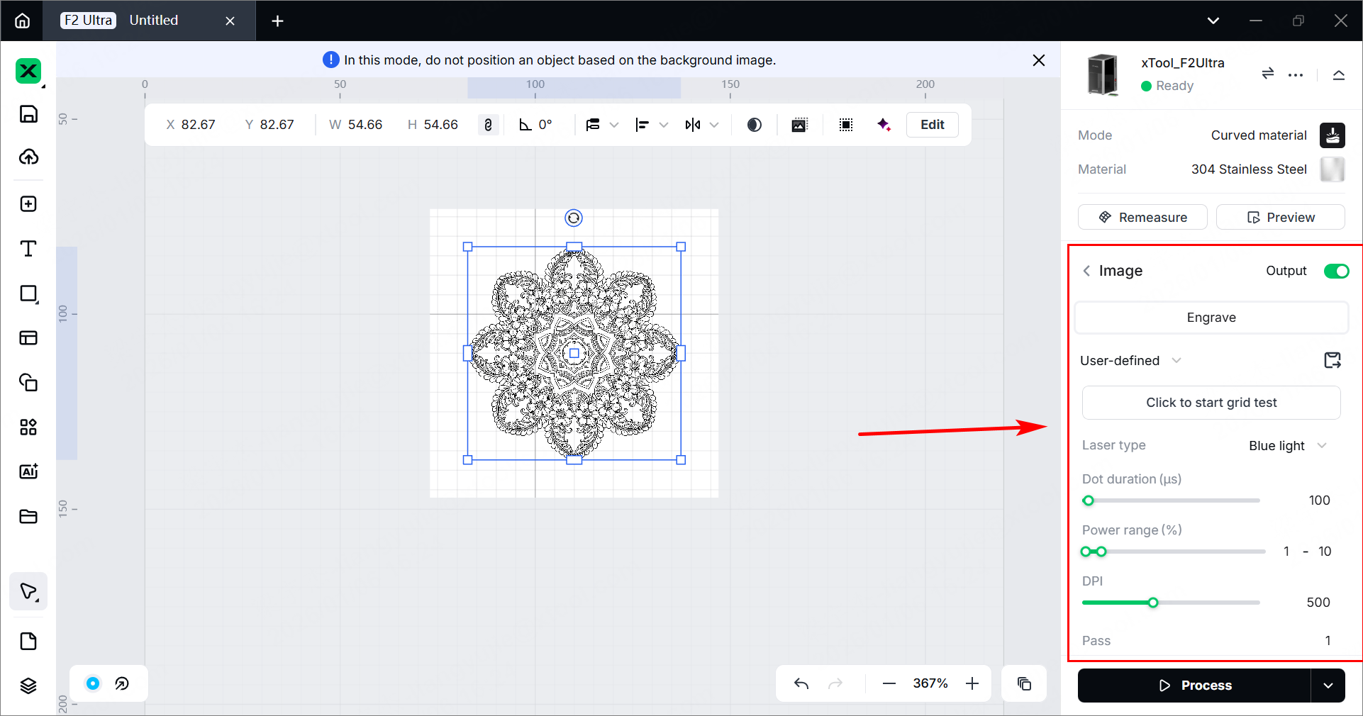
(3) Select objects on the canvas. In the right panel of the page, you can set parameters for the selected objects.
Note:
- You need to set parameters for every object. A missed object may fail to be processed.
- Parameter options differ between bitmap objects and vector objects. You can select multiple objects of the same type and set parameters for them at once.
Note: For more information about the processing parameters, see Processing Parameters for xTool F2 Ultra (Single-Laser Model) or Processing Parameters for xTool F2 Ultra (Dual-Laser Model).
6. Start processing
(1) In the bottom-right corner, click the icon to set the processing path.
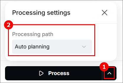
- Auto planning: xTool Studio automatically plans the processing path based on intelligent algorithms.
- By layer: The objects will be processed by the order of the layers.
(2) Turn on or off the Evade smoke mode. When this feature is enabled, the device follows a path less affected by the smoke to process the material.
Note: It is recommended to enable this feature for scoring on materials such as wood and corrugated paper that produce heavy smoke. Otherwise, the heavy smoke may block the laser beams and interfere laser processing.
(3) In the bottom-right corner, click Process.

(4) Click Preview Processing Path and to preview the processing path.
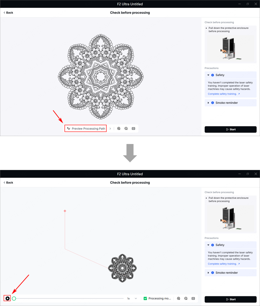
(5) Close the protective enclosure. In the bottom right corner, click Start. When the software shows Ready, press the XTOOL Start/Stop button on the touchscreen controller to start processing.
Services & Help
Learn & Education

Copyright © 2025 xTool All Rights Reserved.