xTool F2 Ultra can be used with rotary attachment 2 (RA2) to process cylindrical materials. With Rotary Attachment 2 Pro, spherical and irregular materials can also be processed.
Note:
- No rotary attachment is included in the pack of xTool F2 Ultra.
- The usage of RA2 and RA2 Pro is the same.
1. Set up the rotary attachment
RA2 Pro supports Roller mode and Chuck mode, while RA2 supports only the Roller mode.
Assemble and set up the rotary attachment according to the selected working mode.
- If you use the Roller mode, set the rotary attachment to A, B, or C level.
Level A | Level B | Level C |
|---|---|---|
Diameter of material: 3 mm ≤ d ≤ 50 mm | Diameter of material: 45 mm ≤ d ≤ 60 mm | Diameter of material: d > 60 mm |
- If you use the Chuck mode, install jaw chuck components and jaw components as required.
Note: For detailed information and instructions on how to use RA2, see xTool Rotary Attachment 2 (RA2) User Guide and Tips for using the L-shaped module of RA2 Pro.
2. Connect the rotary attachment to xTool F2 Ultra
(1) Use the connection cable to connect the rotary attachment to xTool F2 Ultra.
Note: If the connection cable included in the rotary attachment pack is incompatible with xTool F2 Ultra, please purchase a compatible one.
(2) Open the protective enclosure of xTool F2 Ultra and place the rotary attachment on the baseplate of xTool F2 Ultra.
(3) Based on the selected mode and level set for the rotary attachment, align its front bottom edge with the corresponding marking lines on the baseplate of xTool F2 Ultra.
There are four groups of marking lines on the baseplate of xTool F2 Ultra.
- If you use the rotary attachment in Roller mode and set it to Level A, align its front bottom edge with Group 1 marking lines.
- If you use the rotary attachment in Roller mode and set it to Level B, align its front bottom edge with Group 2 marking lines.
- If you use the rotary attachment in Roller mode and set it to Level C or use the Chuck mode, align its front bottom edge with Group 3 marking lines.
- If you use the rotary attachment in Chuck mode and install the L-shaped module on it, align its front bottom edge with Group 4 marking lines.
3. Process with xTool Studio
1. Place the material
- If you use the rotary attachment in Roller mode, place the material between the two rollers.
- If you use the rotary attachment in Chuck mode, secure the material with the jaws.
2. Power on xTool F2 Ultra and connect it to xTool Studio
Refer to Connect and Set Up xTool F2 Ultra with xTool Studio for instructions on connecting xTool F2 Ultra to xTool Studio.
3. Select the processing mode and material
(1) In the right panel of the page, click the current processing mode, and then select Roller - Use rotary attachment or Chuck - Use rotary attachment.
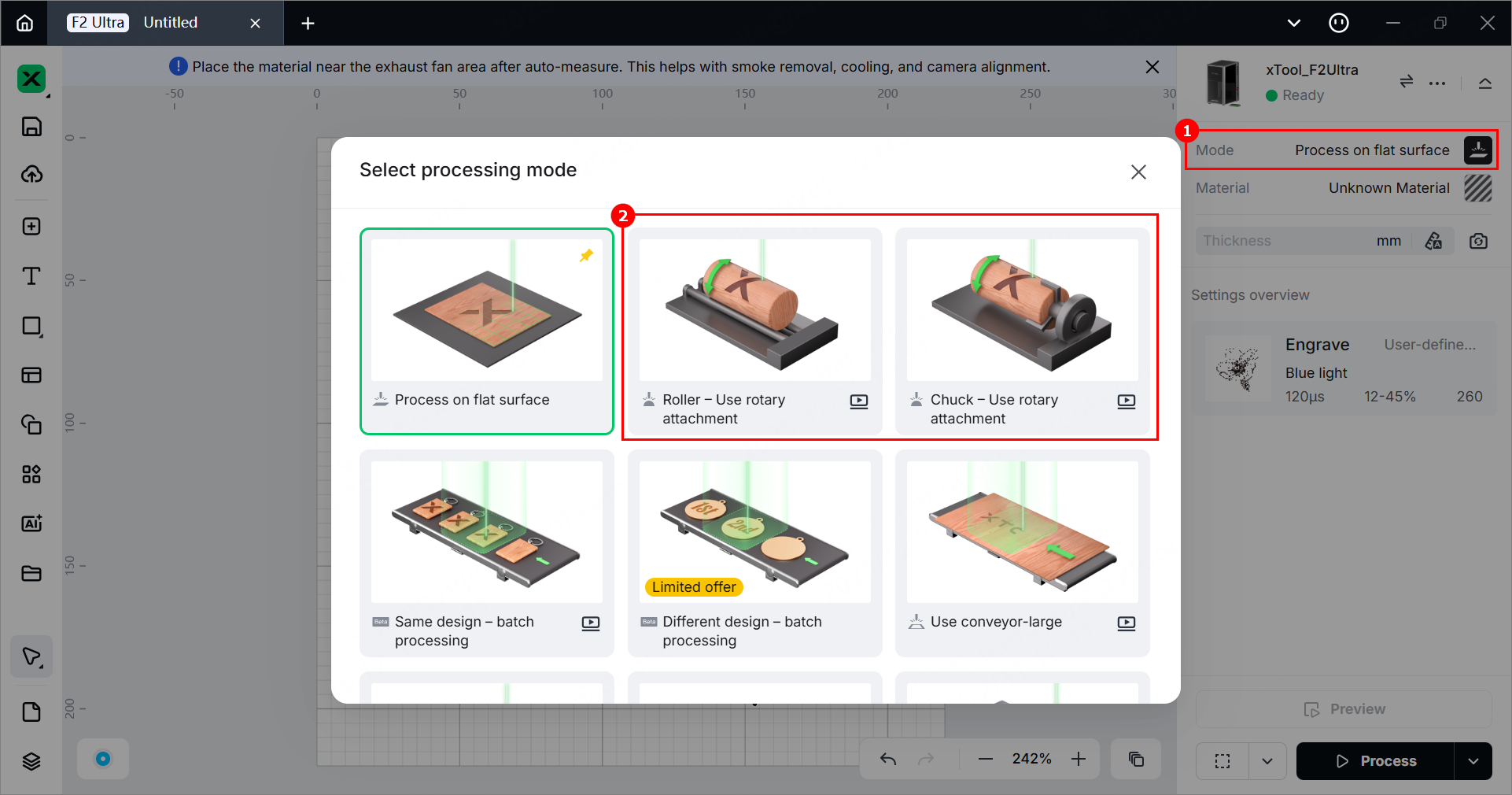
Note: If you select Chuck - Use rotary attachment, you need to enter the Perimeter or Diameter of the material.
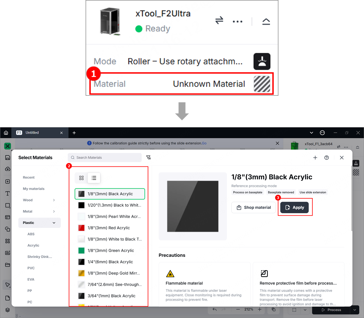
(2) Click Unknown Material, select the desired material, and click Apply.
Note:
- After you select a material from the material list, the software will automatically set parameters for laser processing. The default settings apply to xTool materials. You can adjust the settings as required.
- The recommended parameter settings can achieve the best results only when using xTool's materials. If you are using materials from third parties, it is recommended that you conduct a material test array on your own first to obtain the desired effects and parameters. Meanwhile, make sure that the materials are free from moisture or contamination, which may greatly affect the results.
4. Set the laser focus
(1) Check whether the red and blue light spots are both at the top of the material. If not, follow the steps in "Connect the rotary attachment to xTool F2 Ultra" to readjust the position of the rotary attachment.
(2) Click the Auto-measure icon in the right panel of the page to start auto-focusing. When auto-focusing is complete, xTool Studio displays the thickness of the material, and the red and blue light spots overlap.
5. Design objects for processing
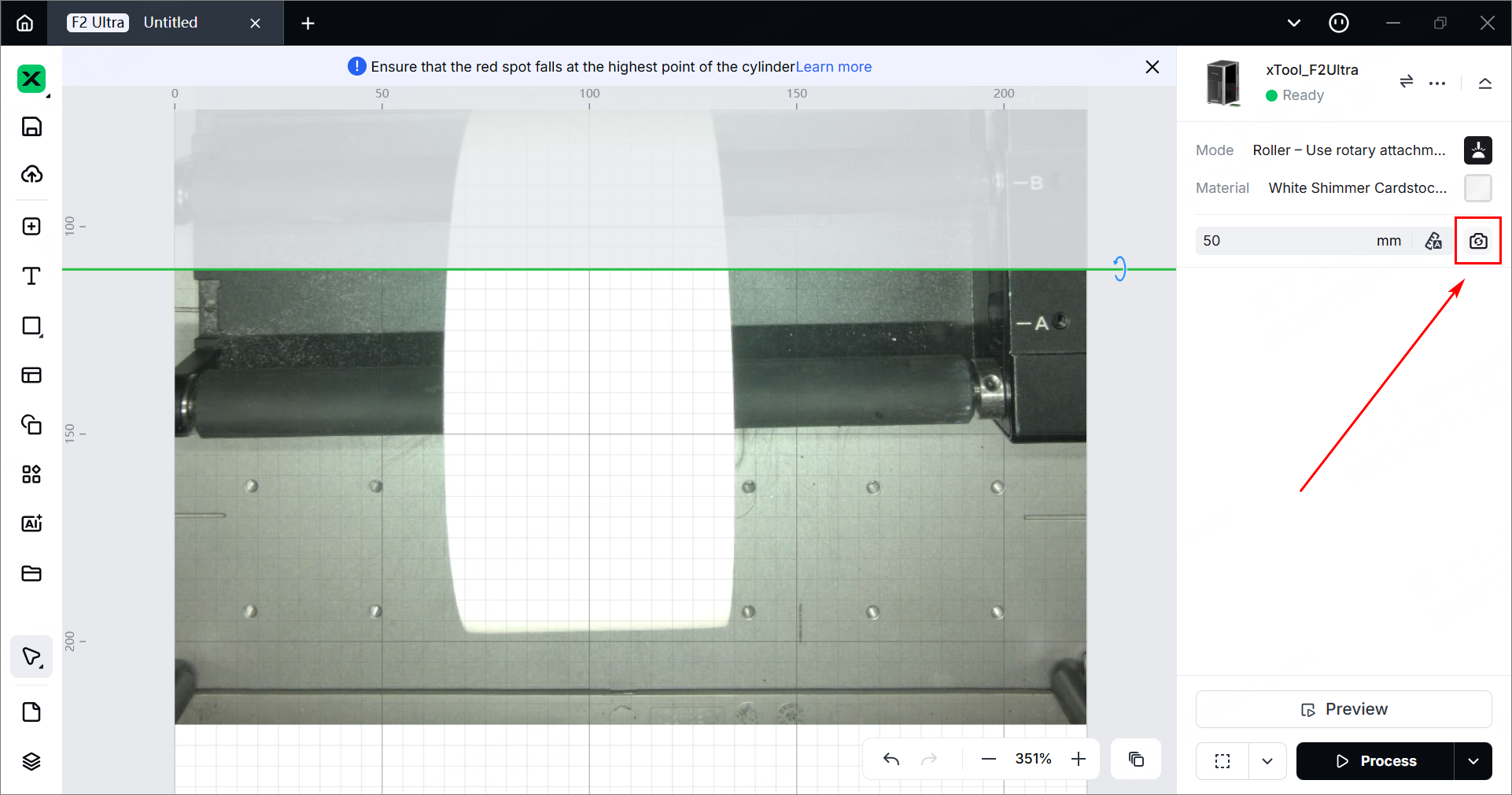
(1) In the right panel of the page, click the icon  to refresh the background.
Note:
- xTool Studio takes a photo of xTool F2 Ultra’s processing area and uses it as the canvas background. You can position processing objects based on the background.
- To ensure positioning accuracy, set the laser focus before shooting the background.
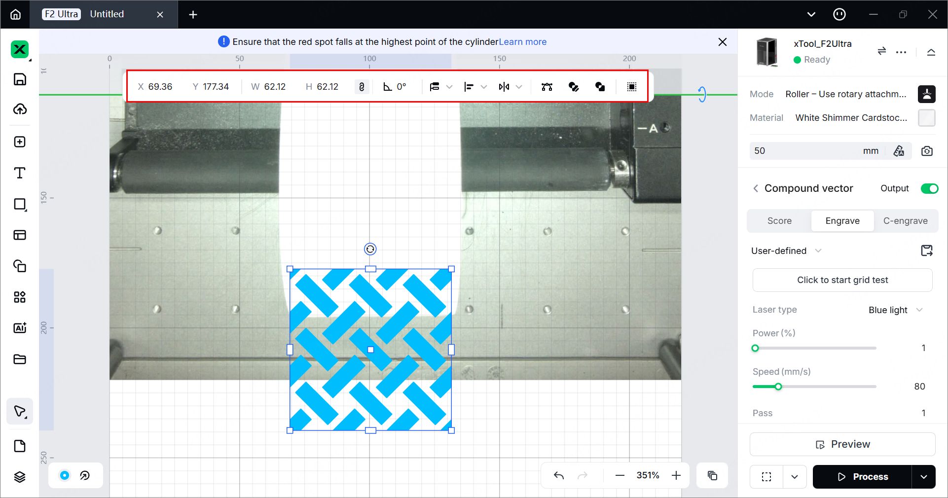
(2) Design processing objects on the canvas below the green line. You can use the tools on the left side of the canvas to import images, insert shapes, enter text, or draw vector graphics.

Note: The gray area above the green line is a non-processing area. Do not place processing objects in this area, or the objects cannot be processed.
(3) After selecting the objects, use the tools above the canvas for further editing.
6. Set parameters for processing
Select objects on the canvas and set their parameters on the right panel.
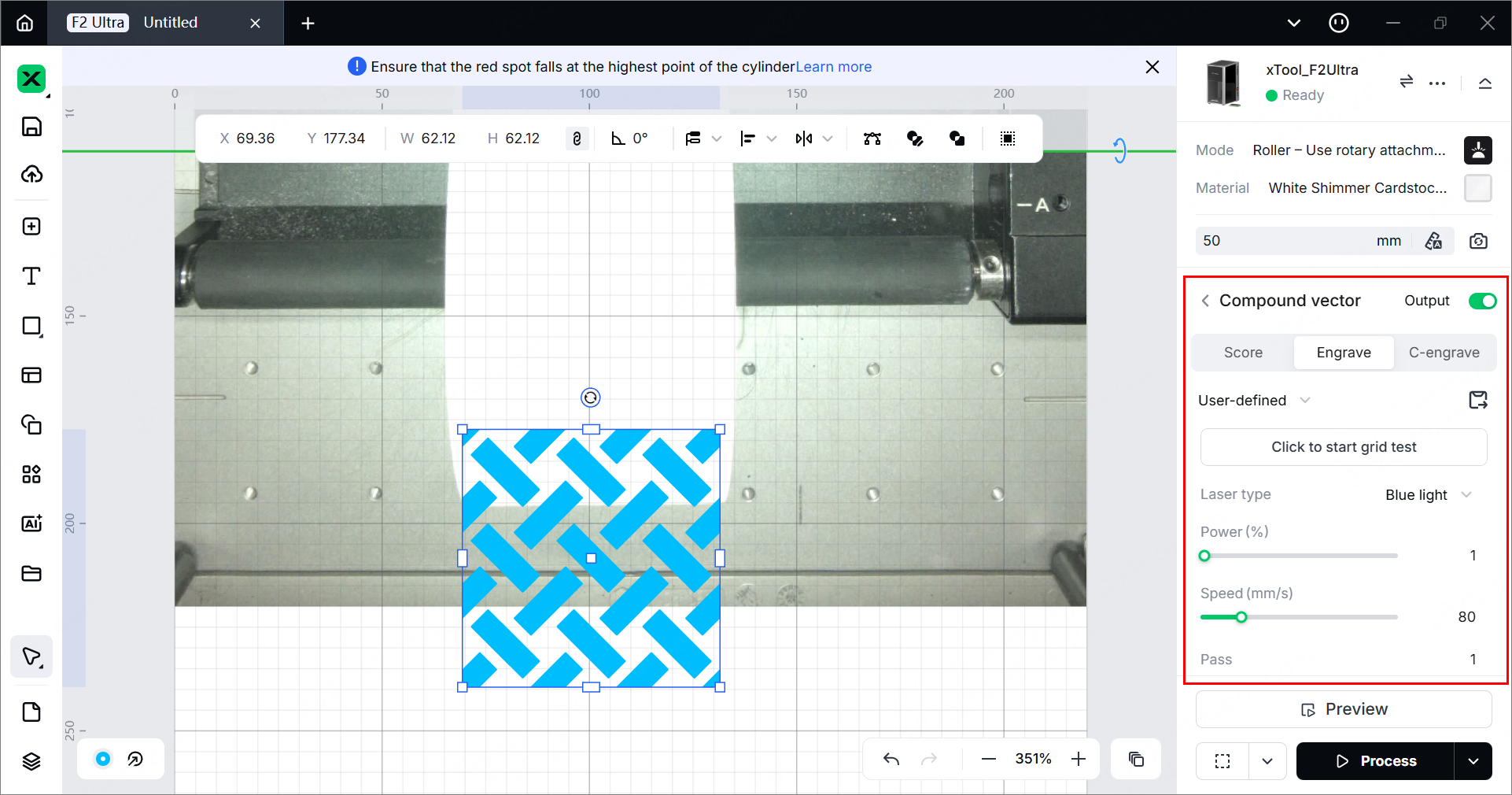
Processing type
- Image - Engrave/C-engrave: Laser beams hit the surface of the material to change the color of the surface. By creating different shades of color on the material surface, xTool F2 Ultra prints an image on the material.
- Vector - Score: Laser beams walk along the path of the vector graphic, drawing the vector on the material with lines.
- Vector - Engrave: Laser beams walk through the entire area enclosed by the vector path, engraving the vector on the material with monochromatic fillings.
- Vector - Cut: Laser beams cut the material along the path of the vector graphic.
Note: You need to set parameters for every object. A missed object may fail to be processed.
Note:
- Parameter options differ between bitmap objects and vector objects. You can select multiple objects of the same type and set parameters for them at once.
- For more information about the processing parameters, see Processing Parameters for xTool F2 Ultra (Single-Laser Model) or Processing Parameters for xTool F2 Ultra (Dual-Laser Model).
7. Set the processing path
(1) Click in the bottom-right corner and set the processing path for processing.
- Auto planning: xTool Studio automatically plans the processing path based on intelligent algorithms.
- User defining: Manually set the processing paths for some objects.
(2) Turn on or off the Evade smoke mode. When this feature is enabled, the device follows a path less affected by the smoke to process the material.
Note: You are advised to enable this feature for scoring on materials such as wood and corrugated paper that produce heavy smoke. Otherwise, the heavy smoke may block the laser beams and interfere laser processing.
8. Preview the processing area
You can preview the processing area on the material by framing. Framing refers to laser dots moving along the boundary of the processing objects on the material. Perform the following steps to start framing.
(1) In the bottom-right corner of the software, click next to the Framing button to set parameters for framing.
In the Rect mode, laser dots move along the rectangle border of the processing objects.
In the Outline mode, laser dots move along the outline of the processing objects.
In the Polygon mode, laser dots move along the polygonal path defined by the object's vertices.
(2) Click the icon in the software. The laser dots will move along the boundary of the processing objects on the material, allowing you to preview the processing area.

By default, xTool F2 Ultra performs framing for all the elements to be processed. To preview the boundary of one or more particular elements, you can select the elements on the canvas of xTool Studio during framing. The laser spot will move along the boundary of the selected elements, as illustrated by the following pictures.
- Default framing:
- Selected elements framing:
9. Start processing
(1) In the bottom-right corner of the software, click Process.
(2) Follow the notes on the right to check whether the device and the material are ready.
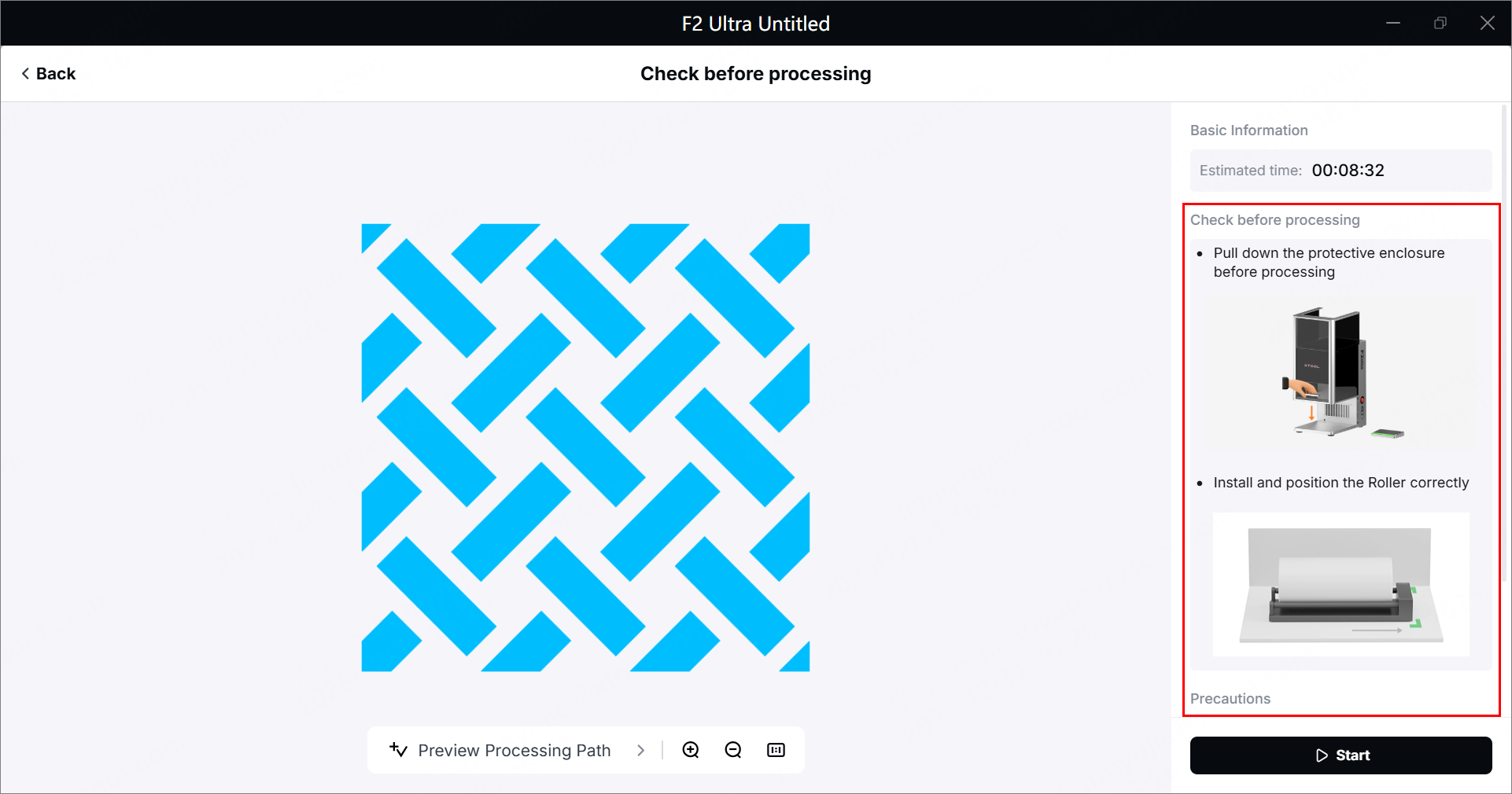
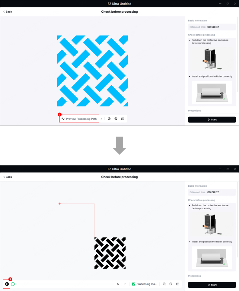
(3) Click Preview Processing Path and to preview the processing path.
(4) Wear a pair of goggles that can shield laser beams of 445 nm and 1064 nm wavelengths.
Safety goggles are not included with xTool F2 Ultra or the rotary attachment. Please purchase them separately.
Note: When xTool F2 Ultra is used with the rotary attachment, its protective enclosure cannot be fully closed. For your safety, it is recommended that you wear goggles during processing.
(5) In the bottom-right corner of the software, click Start.
(6) When the software shows Ready, press the XTOOL Start/Stop button on the touchscreen controller to start processing.
⚠️ Safety reminder: During laser processing, keep the protective enclosure closed or wear goggles that can shield laser beams of 455 nm and 1064 nm wavelengths.
Services & Help
Learn & Education

Copyright © 2025 xTool All Rights Reserved.