This article describes the detailed instructions on how to use xTool Rotary Attachment 3 Lite (RA3 Lite) with xTool M2 in xTool Studio.
For more information about RA3 Lite, refer to xTool Rotary Attachment 3 Lite User Guide.
For more information about xTool M2, refer to xTool M2 User Guide.
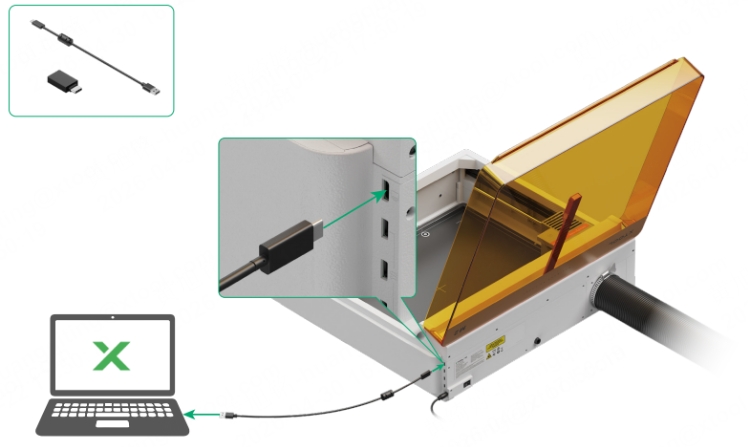
1. Turn on the power switch of xTool M2. Connect xTool M2 to your computer via the USB cable and the adapter included with the device.
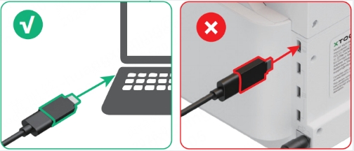
Attention: This adapter is for computer connection only. Do not connect it to xTool M2.
2. Open xTool Studio, and click the + New Project button in the top-right corner.
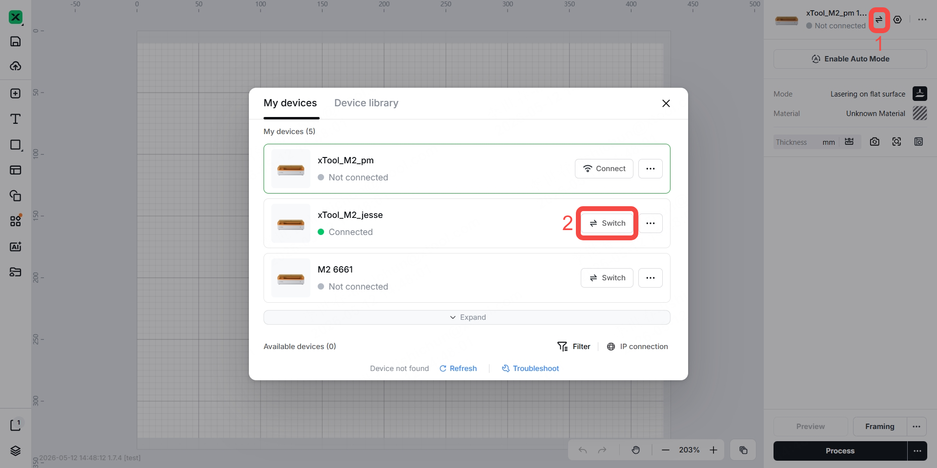
3. Switch to your xTool M2 connected to the computer.
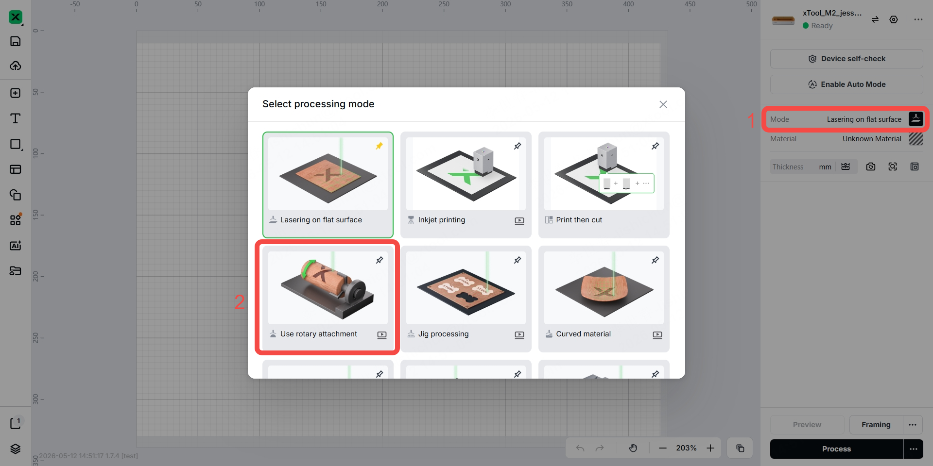
4. Select the Use rotary attachment mode.
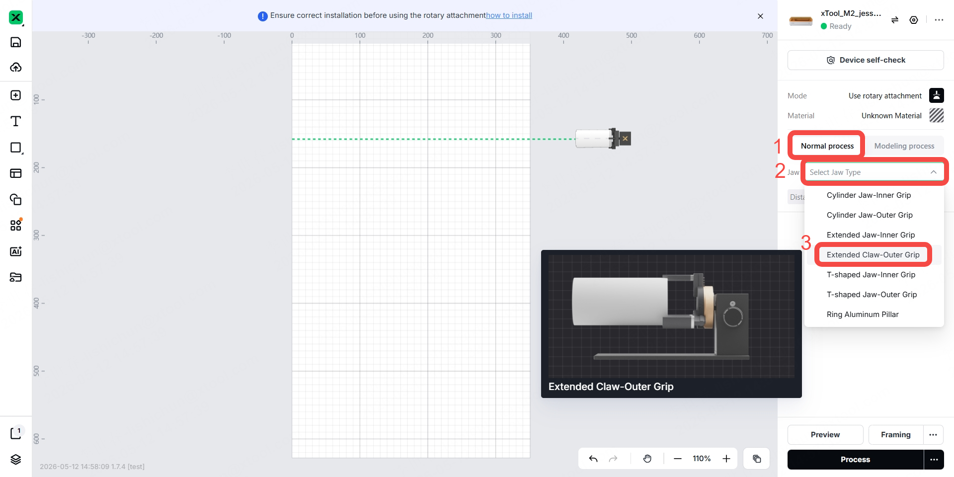
5. Based on your actual needs, select the appropriate jaw and installation method (external clamping or internal clamping) for RA3 Lite.
Note: Click here to view the assembly instructions for RA3 Lite.
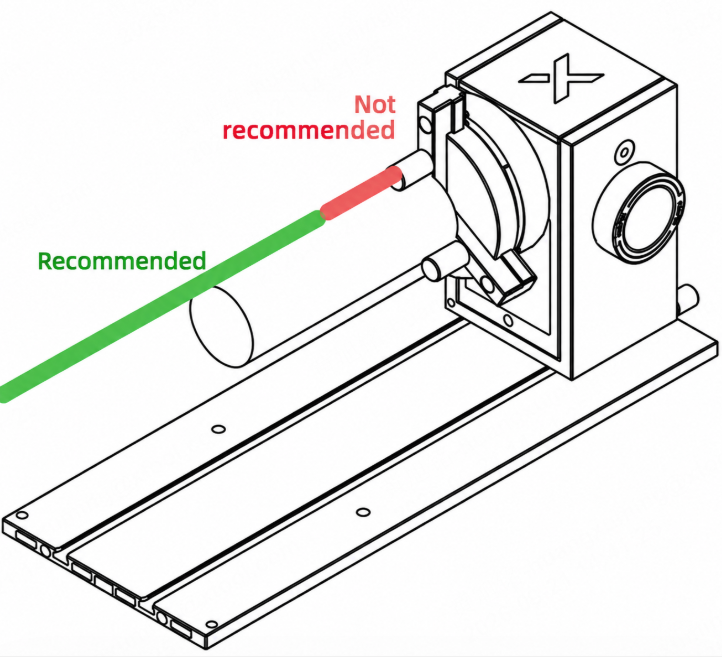
Note: For workpieces with a diameter of less than 80 mm, it is recommended to use the extended jaws. When using the cylindrical jaws, either alone or together with the T-shaped jaws, avoid processing areas close to the jaw chuck, regardless of whether the workpiece is internally or externally clamped. This reduces the risk of the laser module colliding with the jaw chuck. As shown below, avoid processing the area marked in red. The area marked in green is recommended for processing.
The recommended applications for each jaw type and installation method are described below.
(1) "Cylinder Jaw-Inner Grip": When used for internal clamping, the cylindrical jaws are primarily suitable for processing small-diameter hollow rotary workpieces.

(2) "Cylinder Jaw-Outer Grip": When used for external clamping, the cylindrical jaws are primarily suitable for processing small-diameter rotary workpieces.
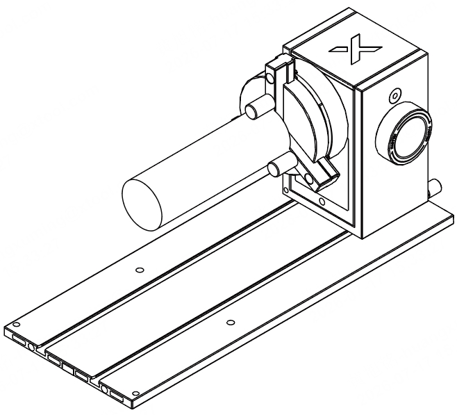
(3) "Extended Jaw-Inner Grip": When used for internal clamping, the extended jaws are primarily suitable for processing hollow rotary workpieces with a diameter of less than 80 mm. It is recommended to mount the extended jaws in the middle or the innermost holes of the jaw chuck.

(4) "Extended Claw-Outer Grip": When used for external clamping, the extended jaws are primarily suitable for processing rotary workpieces with a diameter of less than 80 mm. It is recommended to mount the extended jaws in the middle or the innermost holes of the jaw chuck.

(5) "T-shaped Jaw-Inner Grip": When used for internal clamping, the combination of cylindrical jaws and T-shaped jaws are primarily suitable for processing large-diameter hollow rotary workpieces. It is recommended to mount them in the outermost holes of the jaw chuck.

(6) "T-shaped Jaw-Outer Grip": When used for external clamping, the combination of cylindrical jaws and T-shaped jaws are primarily suitable for processing large-diameter rotary workpieces. It is recommended to mount them in the outermost holes of the jaw chuck.

(7) "Ring Aluminum Pillar": The stud components are suitable for processing rings.

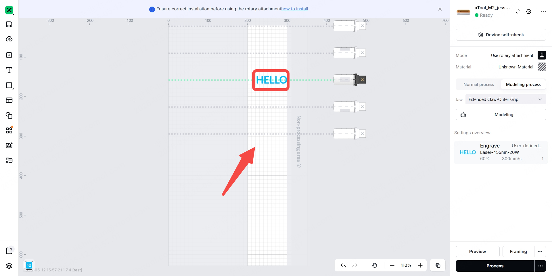
6. Place the design element on the central axis of RA3 Lite.
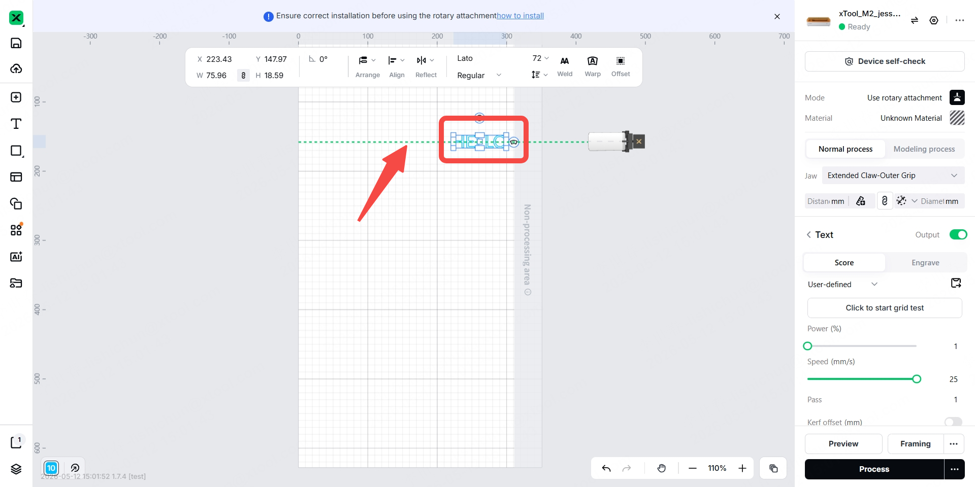
Note: Make sure the design element is placed within the white processing area and not in the gray non-processing area. The canvas length does not match the actual length of the workpiece. If the design is placed too close to the left edge of the canvas, part of it may fall outside the actual processing area on the workpiece.
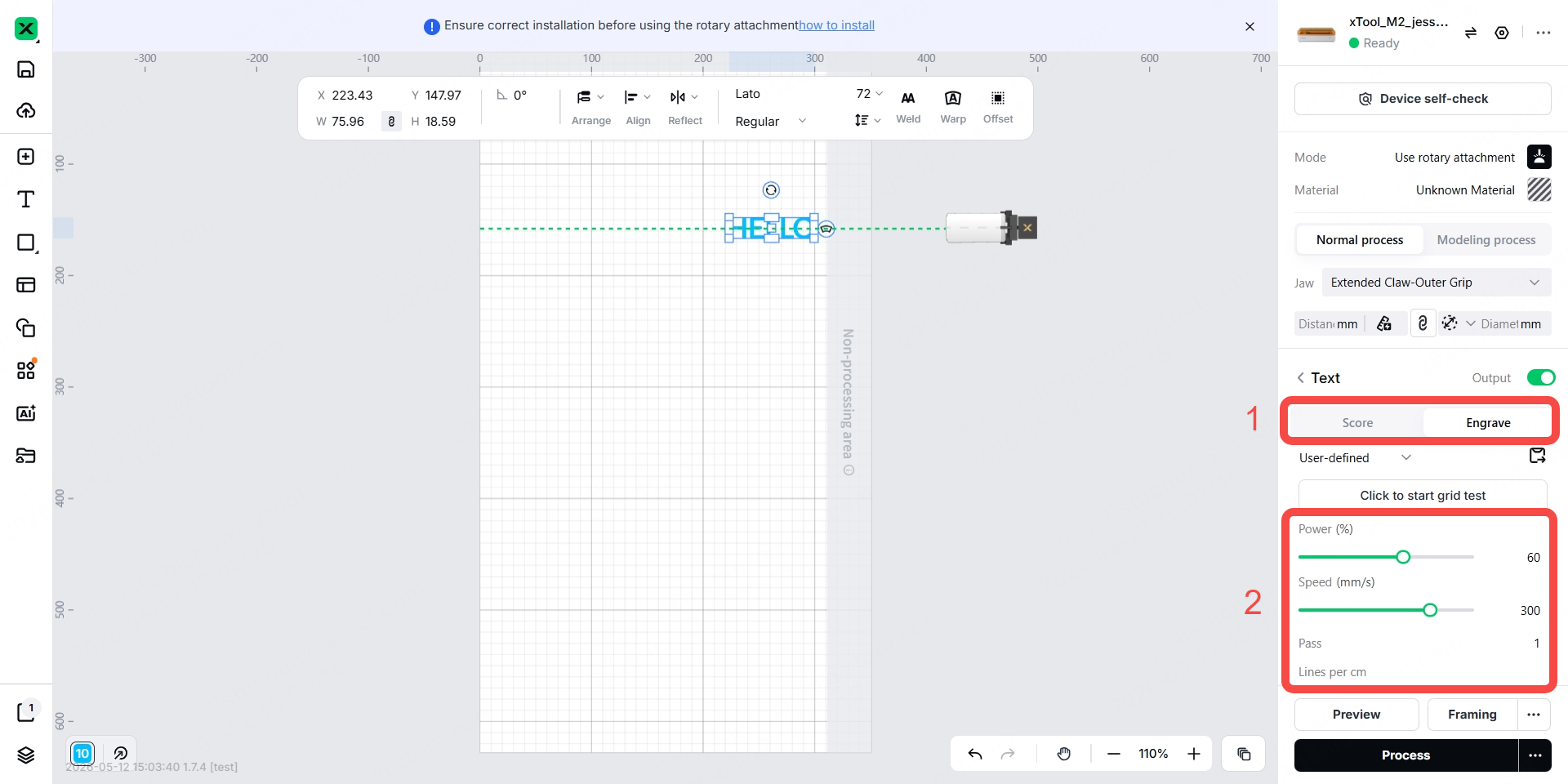
7. Select either Score or Engrave as needed, and then configure the processing parameters in the lower-right corner.
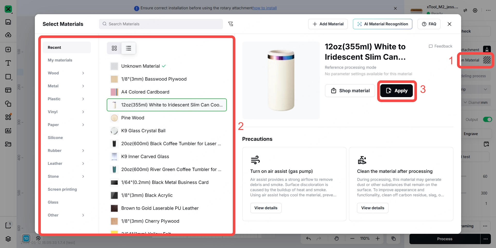
8. Select the material you use (click Unknown Material in the upper-right corner, choose a material from the left side of the Select Materials pop-up window, and then click Apply).
Note: If you are using a standard cylindrical workpiece or a ring, skip Steps 9–18 and continue from Step 19.
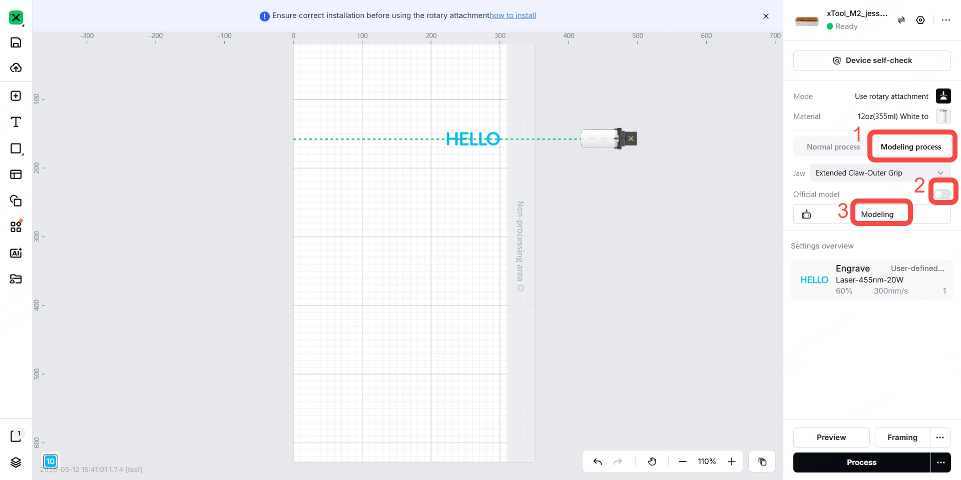
9. If you are using an official non-cylindrical material with an official model, click Modeling process, enable Official model, and then click Calibrate.
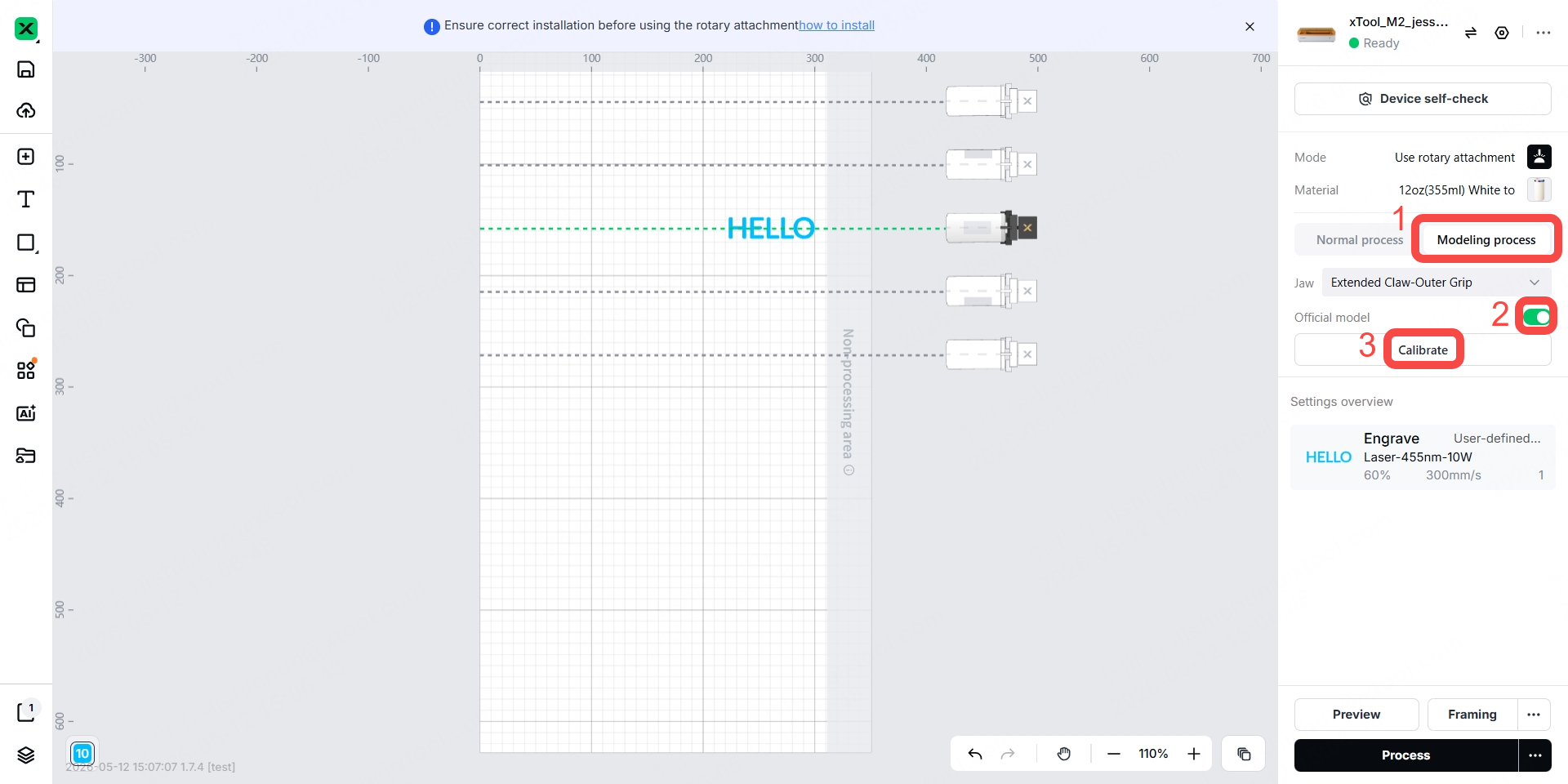
Note: Normal process is suitable for workpieces with standard cylindrical surfaces and for rings, and Modeling process is suitable for certain official materials and for workpieces with non-cylindrical surfaces.
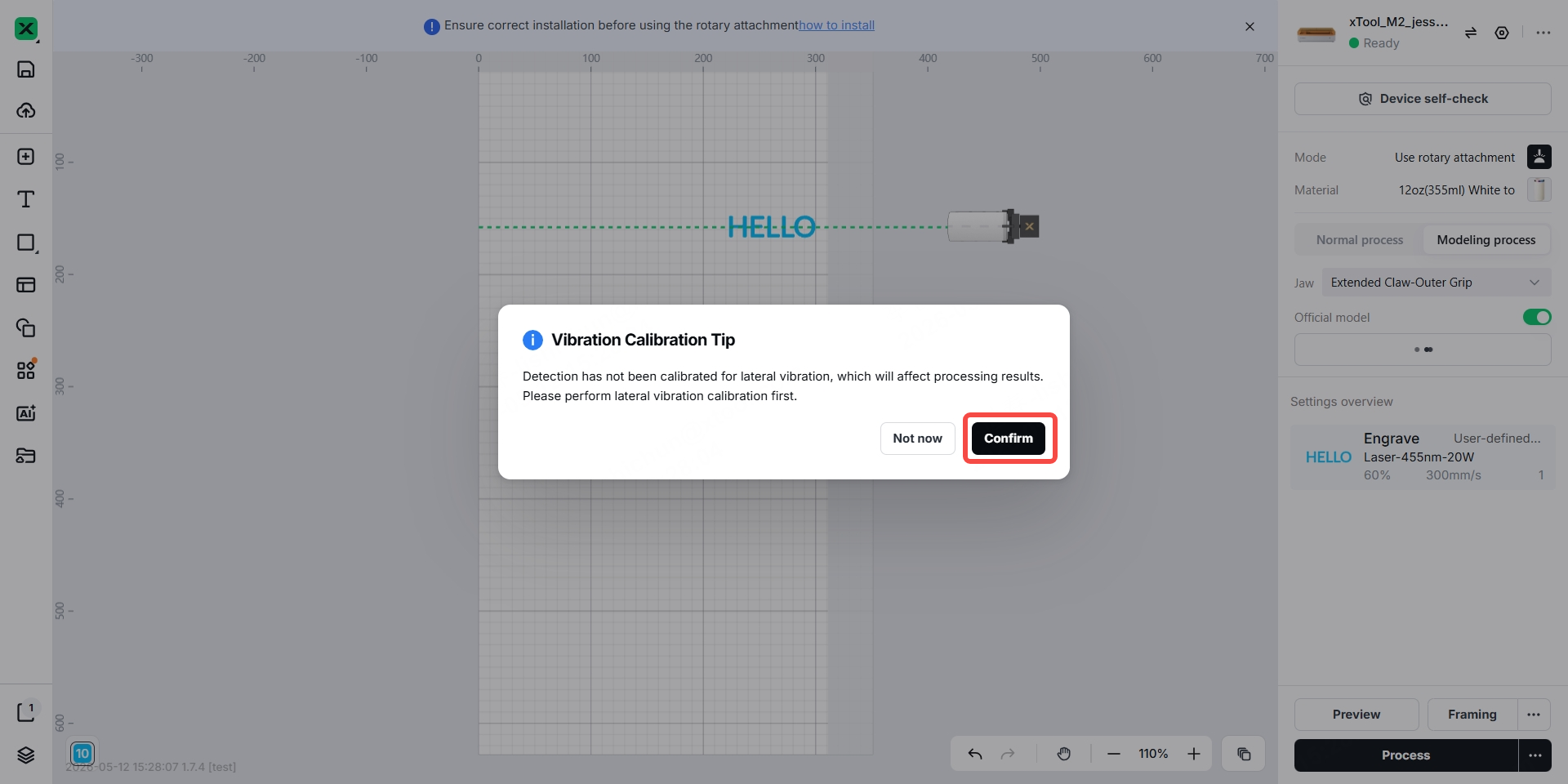
10. In the Vibration Calibration Tip pop-up window, click Confirm to perform horizontal vibration calibration.
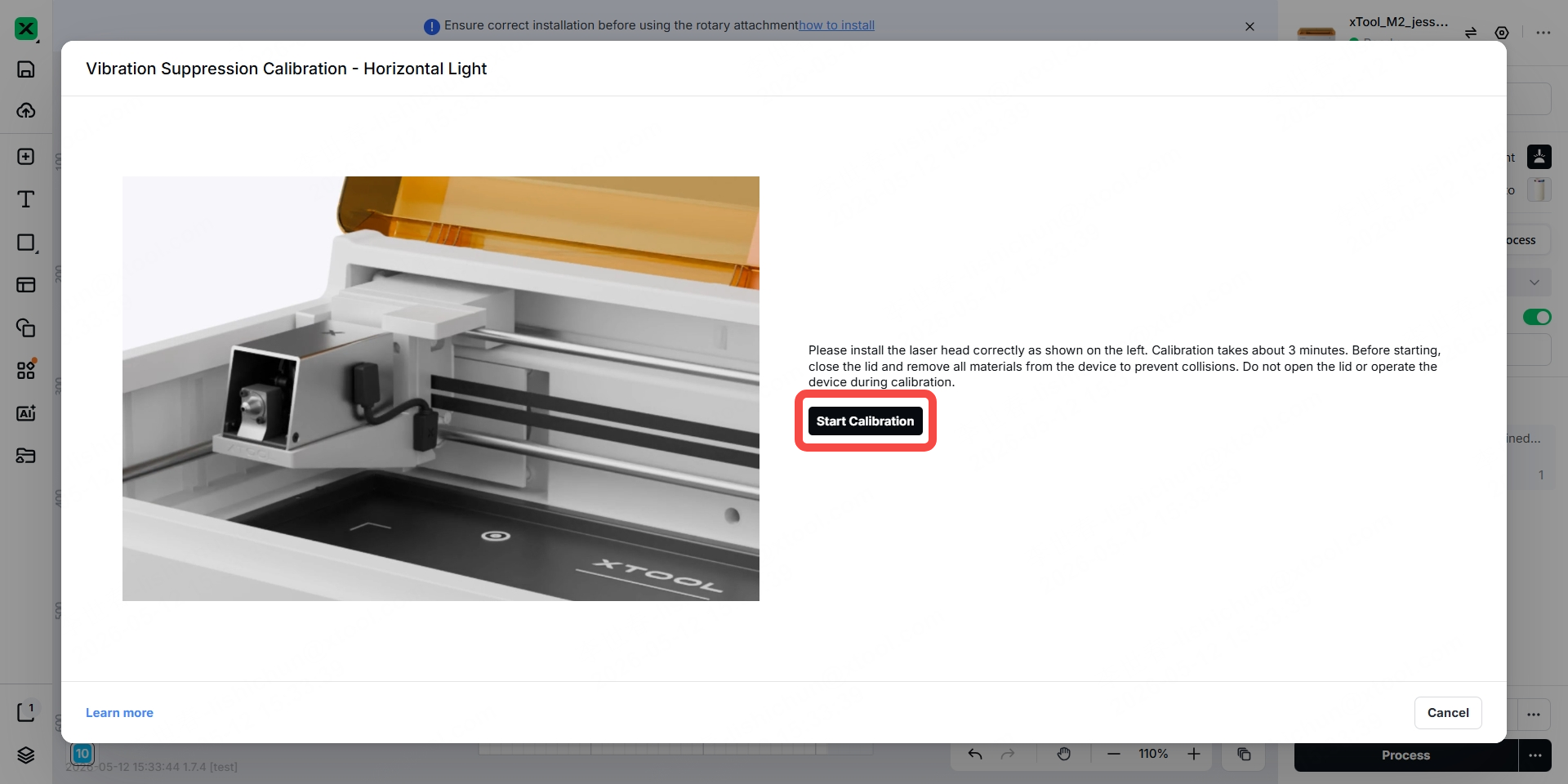
11. Click Start Calibration to begin the horizontal light vibration suppression calibration. The calibration is expected to take a few minutes. Please wait patiently.
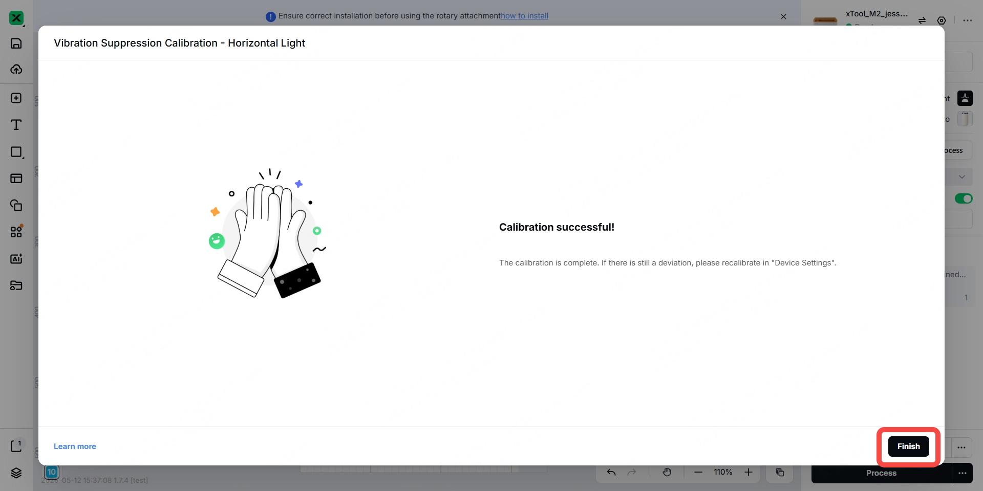
12. After the calibration is complete, click Finish.
13. If you are using an official material without a model, or processing a non-cylindrical workpiece, click Modeling process, disable Official model, and then click Modeling.
14. Follow the on-screen instructions and click the left or right arrow to move the laser module. After reaching Vertex 1, click Mark.
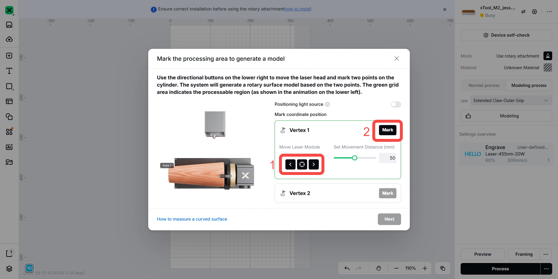
Note: You can adjust the number in the box to set the distance the laser module moves each time.
15. Follow the on-screen instructions and click the left or right arrow to move the laser module. After reaching Vertex 2, click Mark.
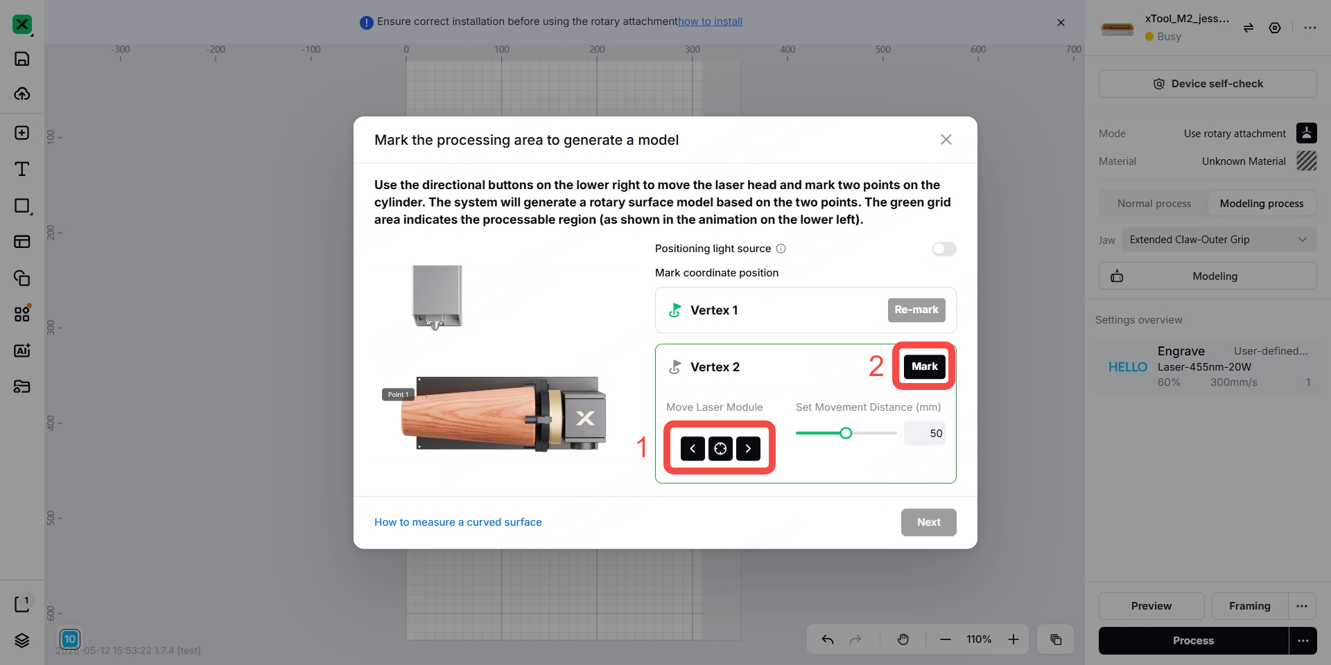
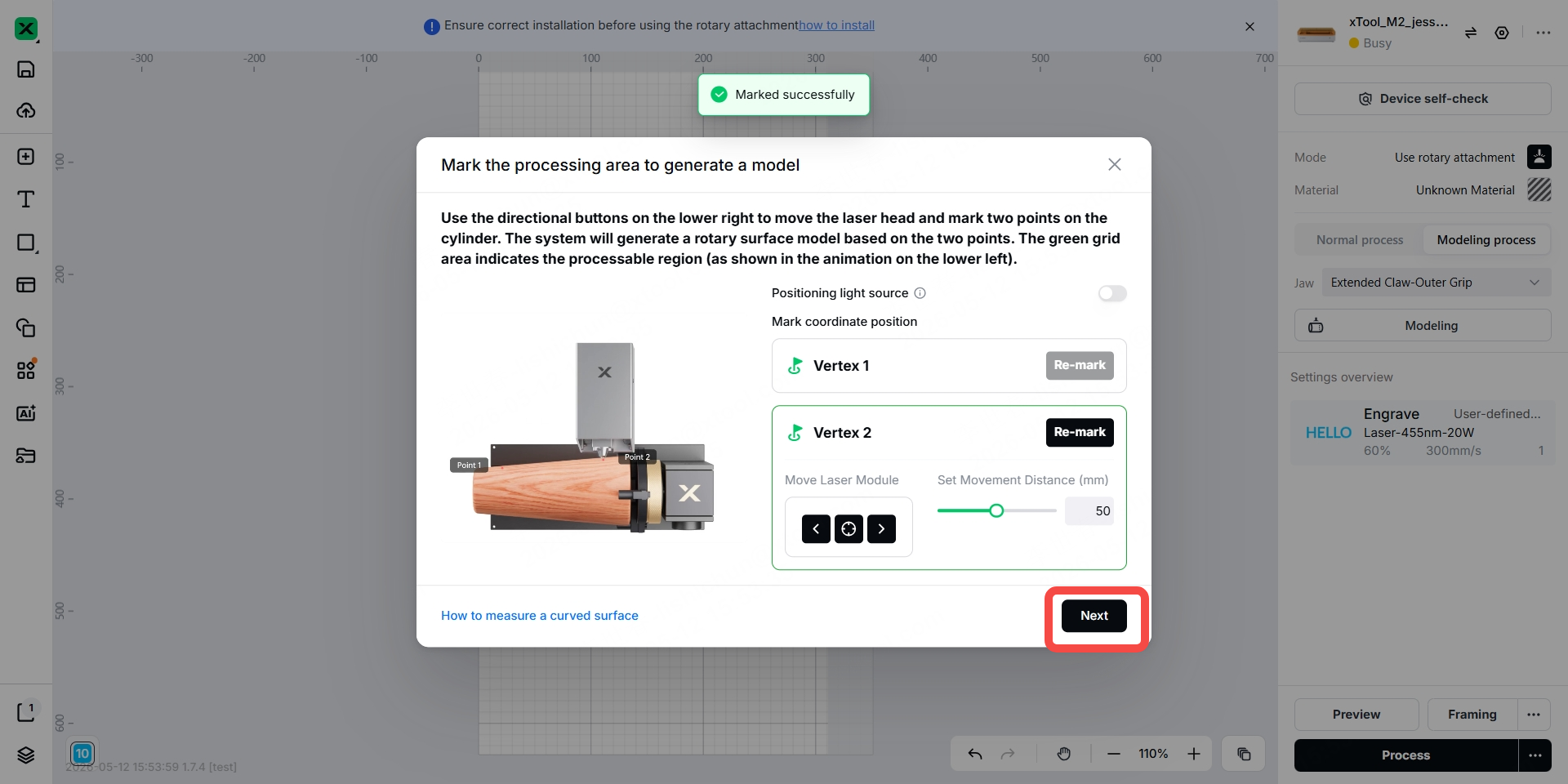
16. After marking Vertex 2, click Next.
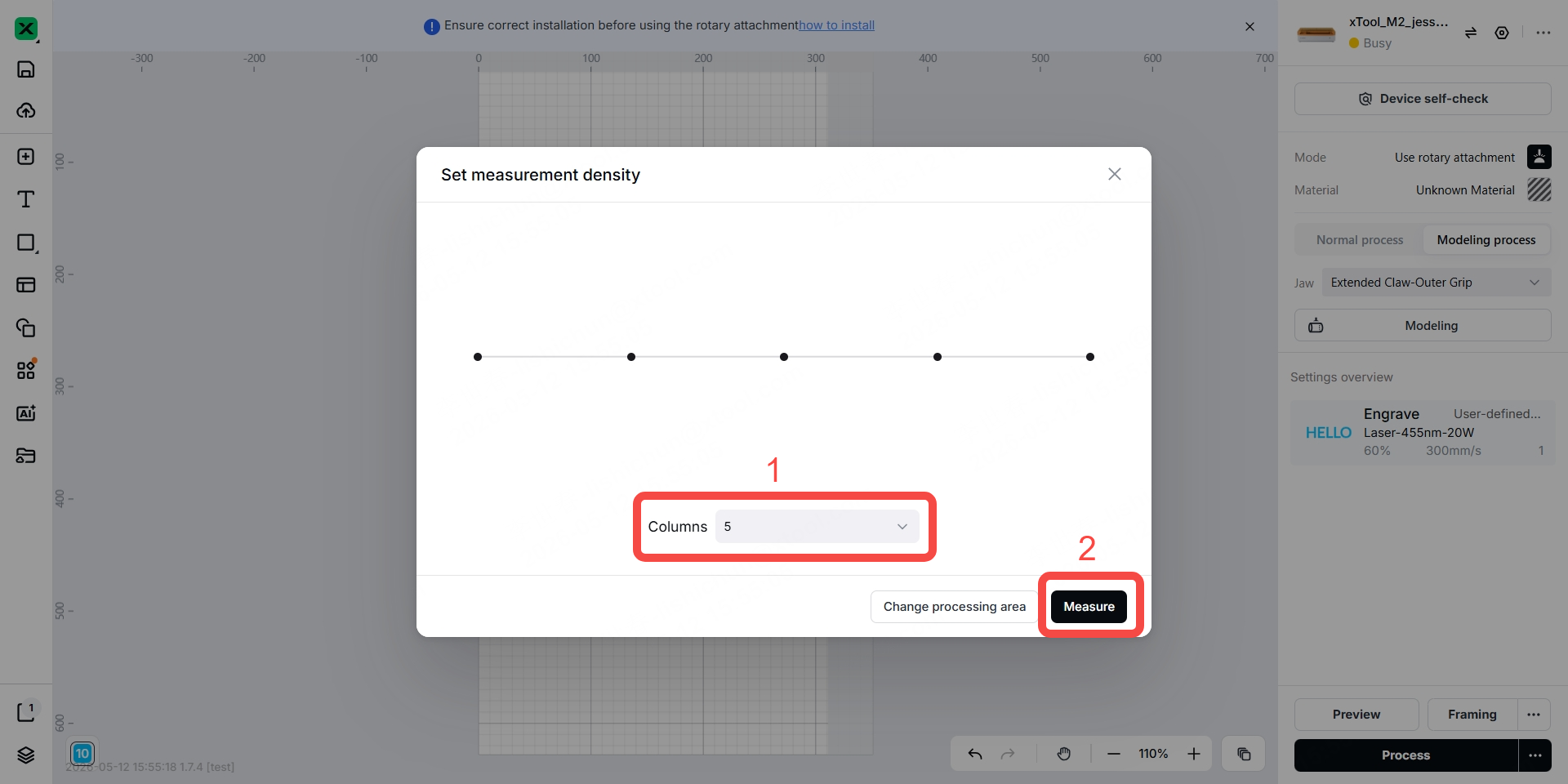
17. Adjust the number of columns to set the measurement density, then click Measure.
18. Ensure that the design element is within the processing area indicated by the white background.
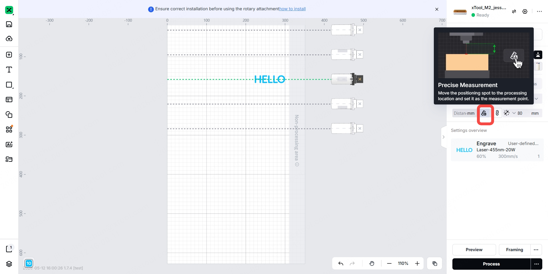
19. If you are using a standard cylindrical workpiece or a ring, click the Precise Measurement icon under the Normal process tab.
Note: To create a precise full-wrap engraving without overlapping the start and end of the design, secure the workpiece firmly, remove the handle if applicable, and use the support module. M2 supports workpiece modeling and precise distance measurement. After modeling the workpiece, position your design as shown below, with its top and bottom edges aligned with the uppermost and lowermost horizontal guide lines, respectively. This helps align the start and end of the design for a seamless full-wrap engraving.

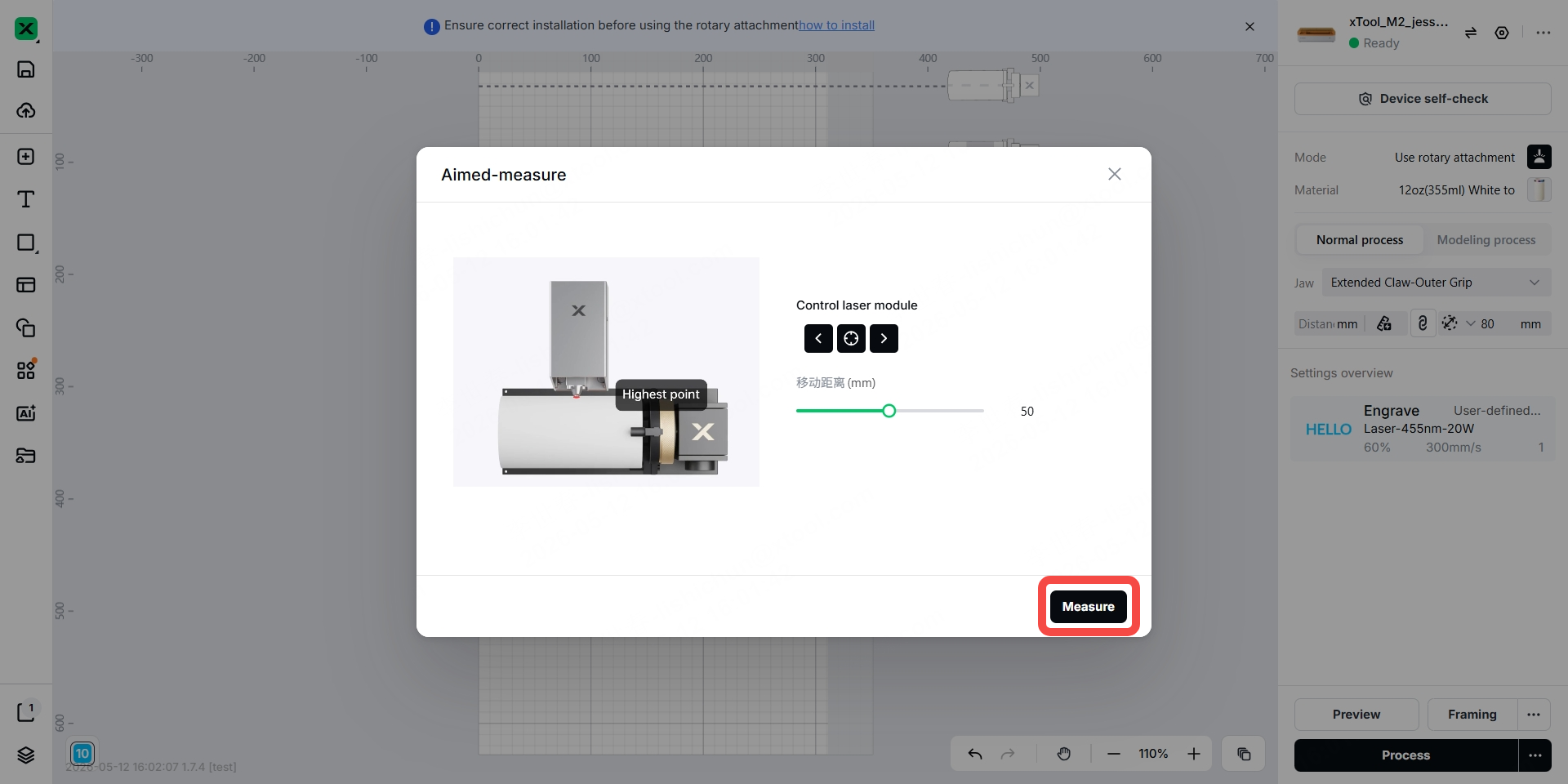
20. Follow the on-screen instructions to move the laser module, then click Measure to perform precise measurement.
Note: (1) If the icon in the red box is as shown below, the system will automatically measure the workpiece diameter while performing distance measurement.
If the workpiece diameter is ≤ 55 mm, do not install the support module. Otherwise, the laser module may collide with the support module during processing.
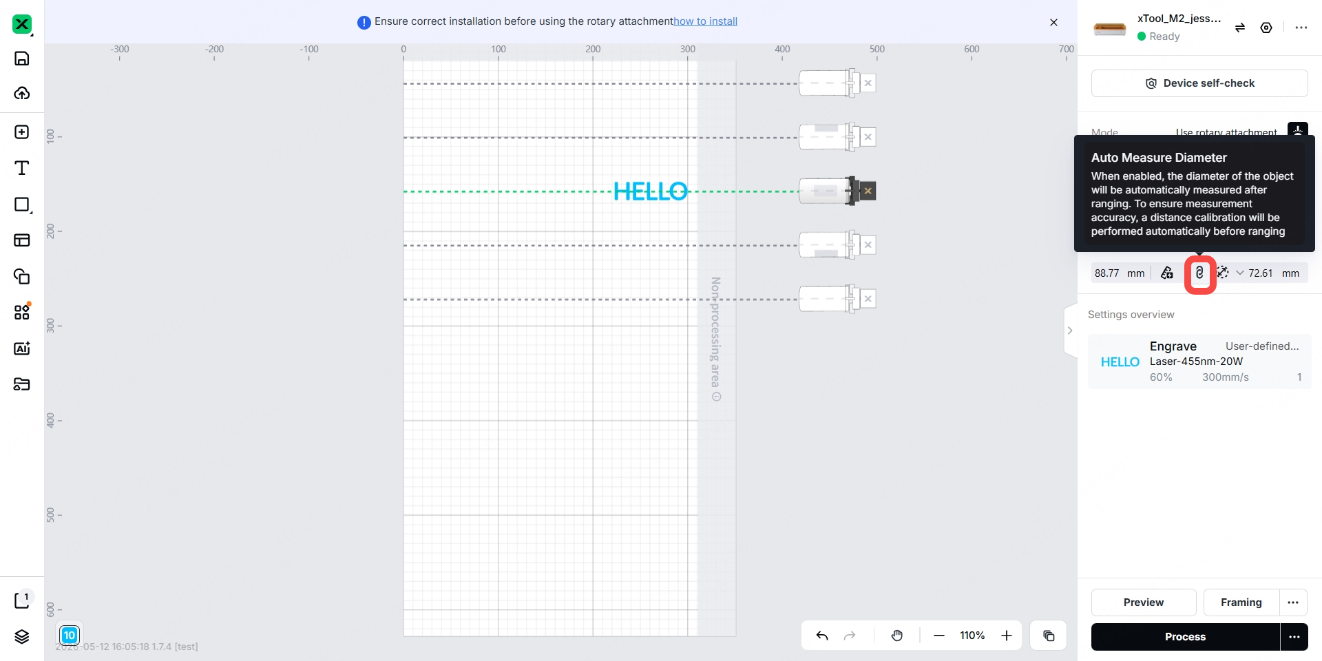
(2) If the icon in the red box is as shown below, you need to manually measure the workpiece diameter and enter it into the input field next to the icon.
If the workpiece diameter is ≤ 55 mm, do not install the support module. Otherwise, the laser module may collide with the support module during processing.
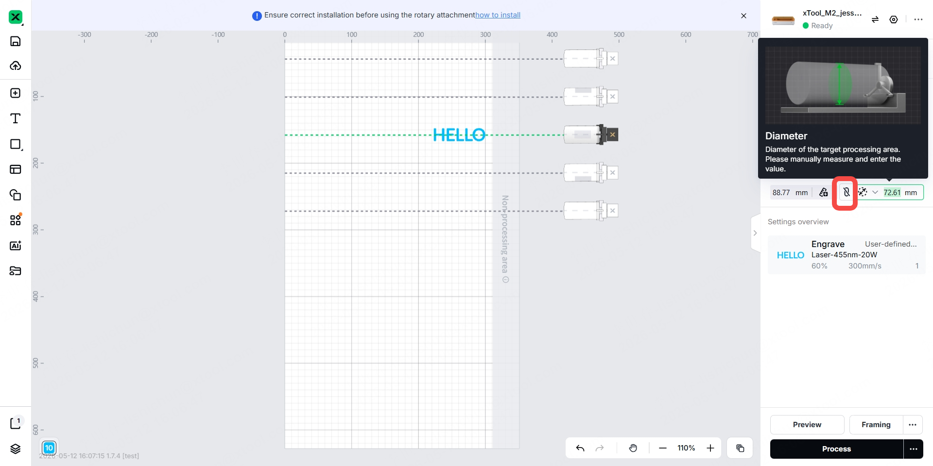
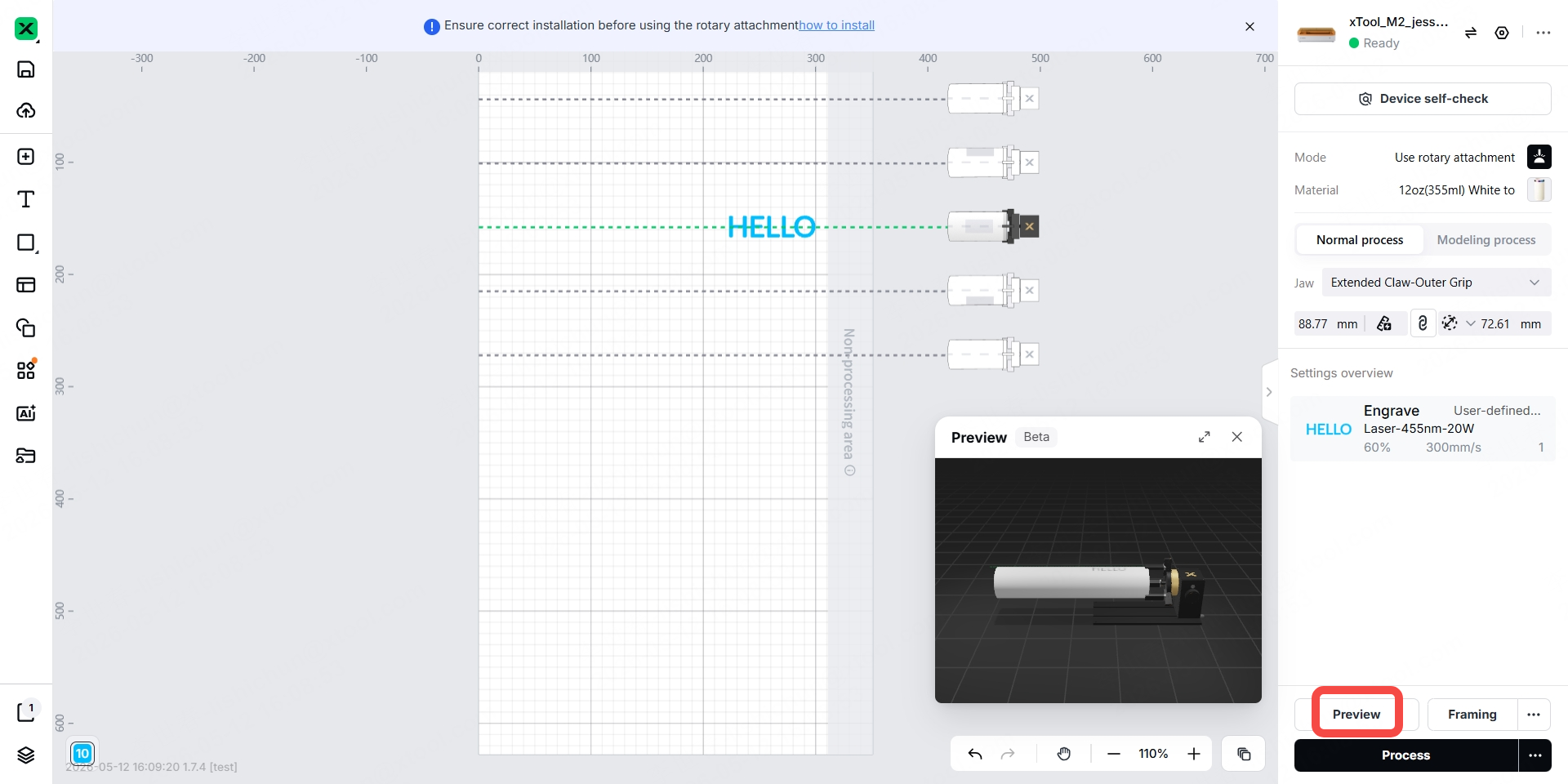
21. Click Preview to view the position of the design element on the workpiece.
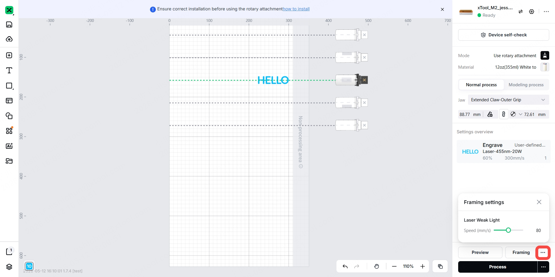
22. Click the “…” to the right of Framing to set the framing speed.
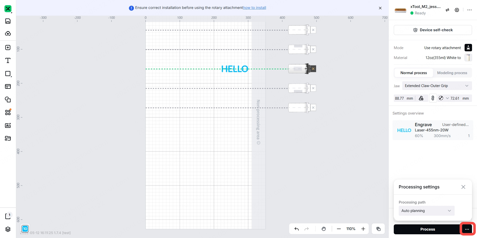
23. Click the “…” to the right of Process to set the processing path.
24. Click Process.
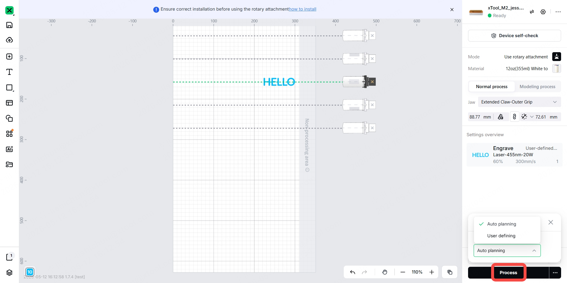
25. (Optional) Click Preview Processing Path to view the processing path.
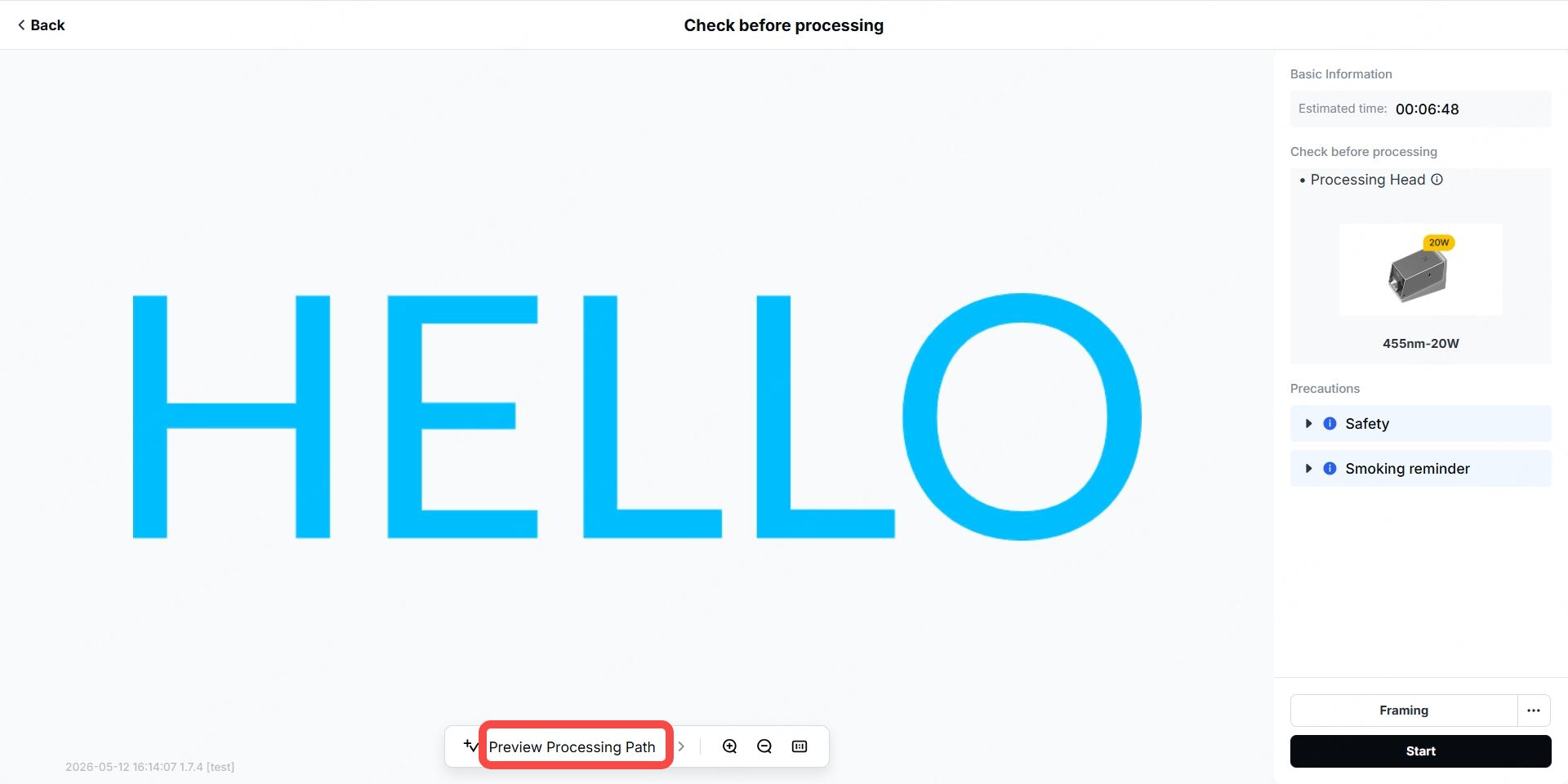
- Click Start.
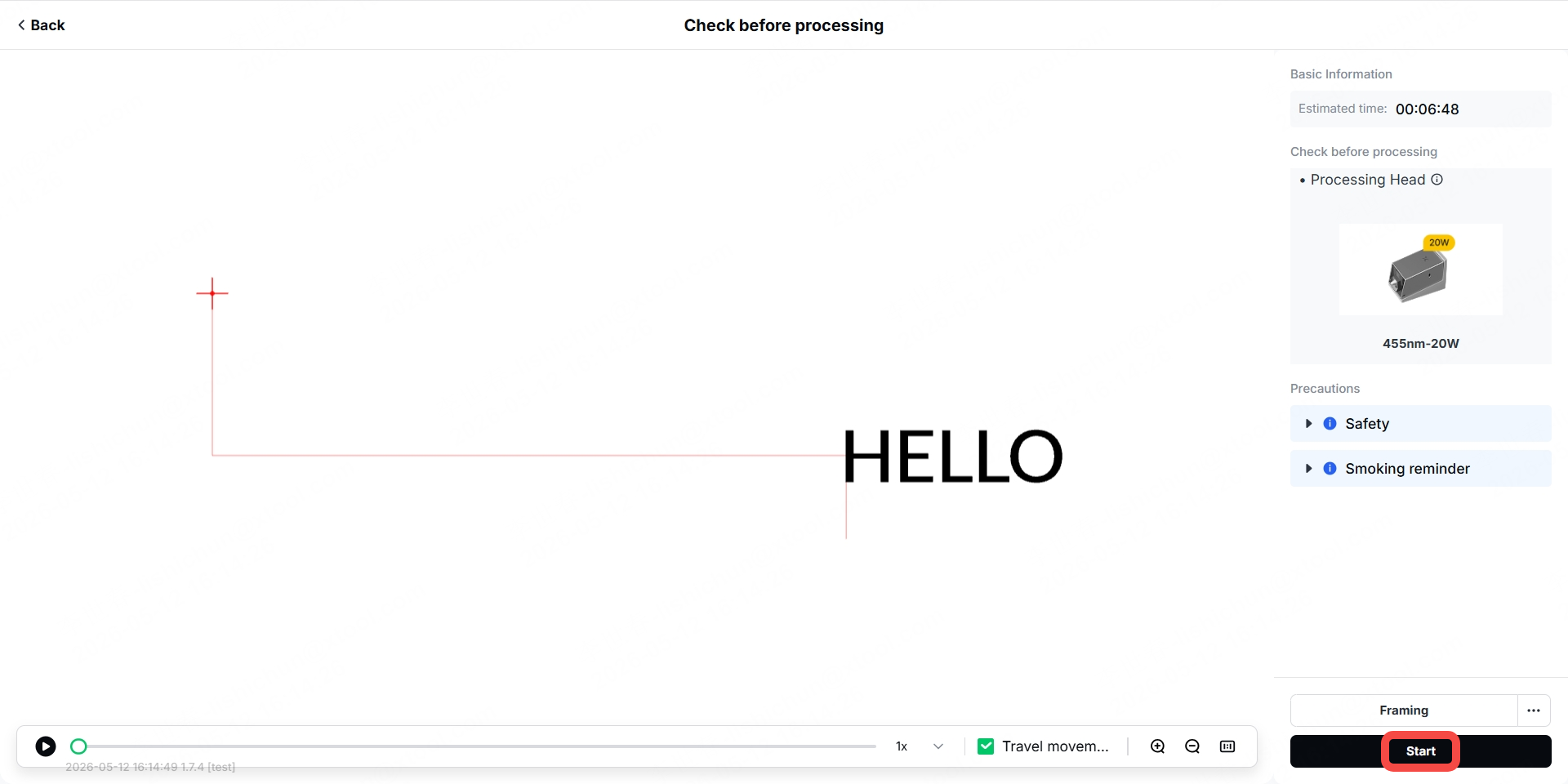
27. Follow the on-screen instructions and press the button on xTool M2 to start processing.
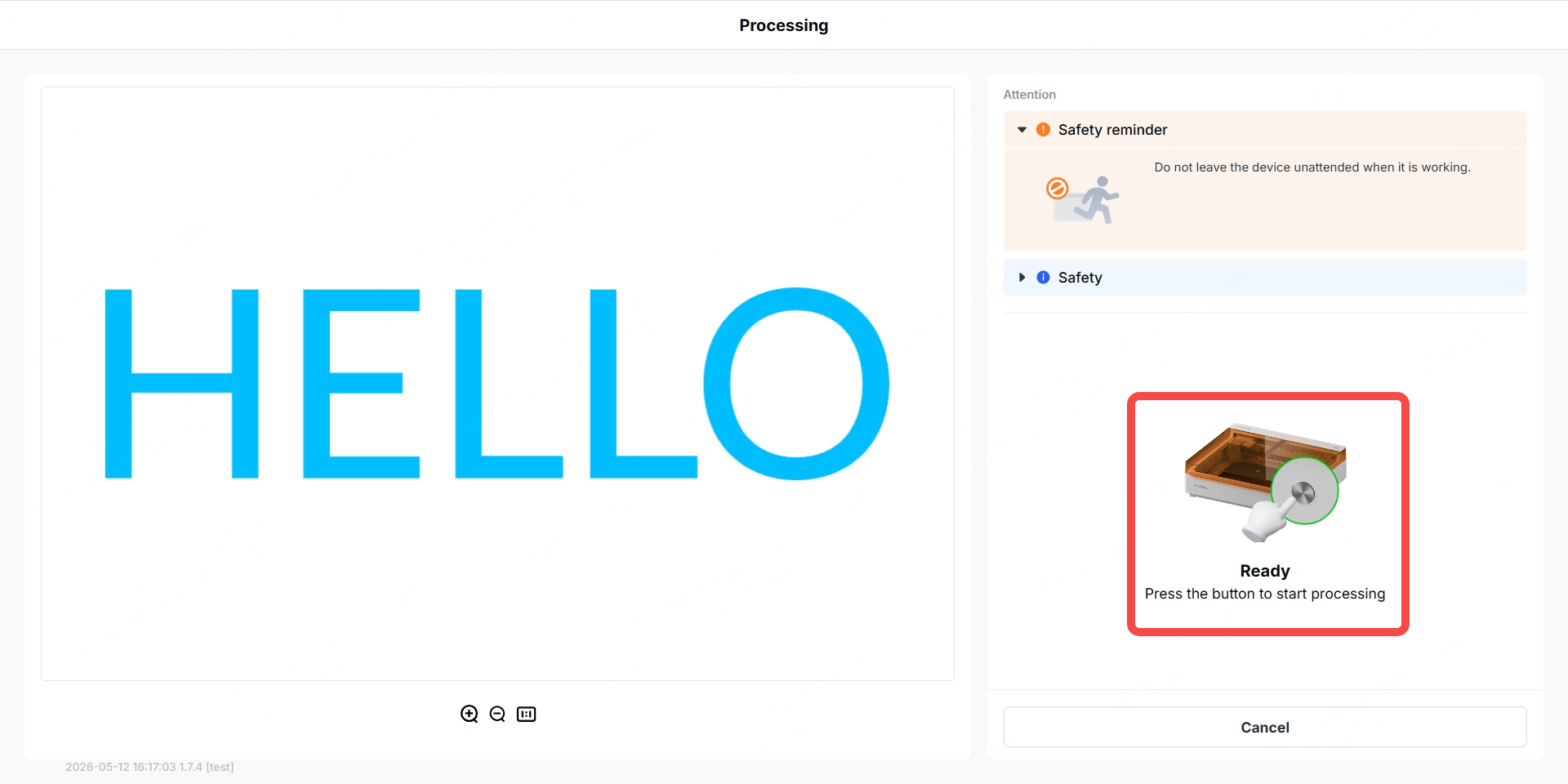
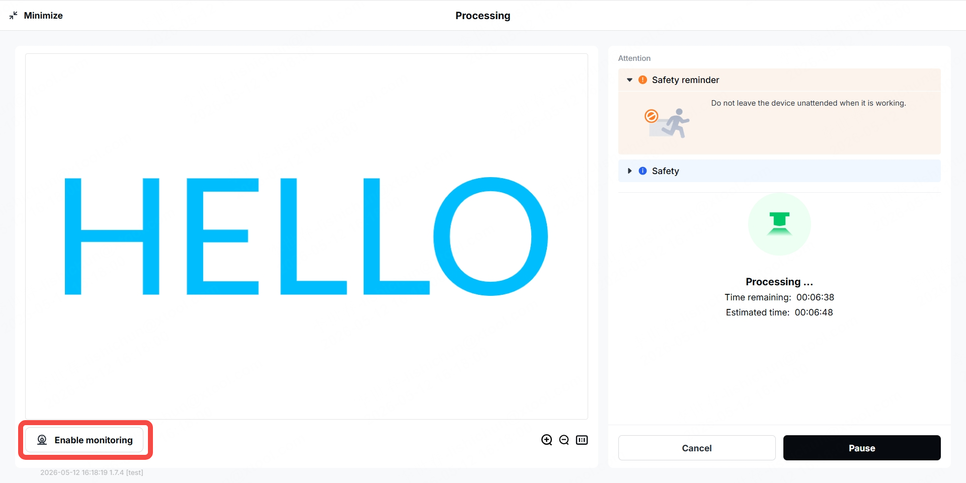
28. (Optional) During processing, click Enable monitoring to view the progress in real time.
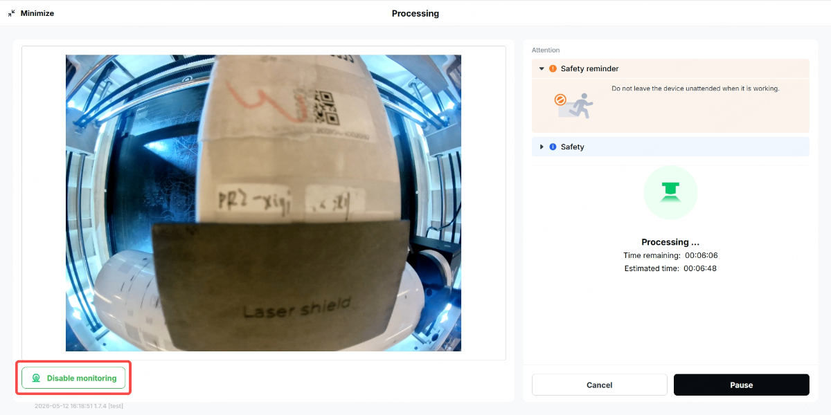
29. (Optional) If you no longer want to view the processing progress in real time, click Disable monitoring.
30. After processing is complete, click Finished to end the current job.