1. Place the material
Lift the protective enclosure and place the material on the baseplate, allowing the blue light spot to fall on the surface of the material.
Note: If the material to be processed is very small or lightweight, secure it with tape or similar tools. Otherwise, the airflow from the exhaust fan may cause the material to shift during processing.
To cut the material, place the slatted panel on the baseplate, then place the material on top of the panel.
💡 Important:
The slatted panel helps reduce burn marks during material processing and protects the baseplate. For optimal results, install the slatted panel correctly:
- Correct Installation: Position the gaps between the slats perpendicular to the exhaust outlet to allow proper airflow. Refer to the images above.
- Incorrect Installation: Horizontal installation may block airflow and compromise performance.
2. Connect xTool F2 Ultra to xTool Studio
Refer to Connect and Set Up xTool F2 Ultra with xTool Studio for instructions on connecting xTool F2 Ultra to xTool Studio.
3. Select the processing mode and material
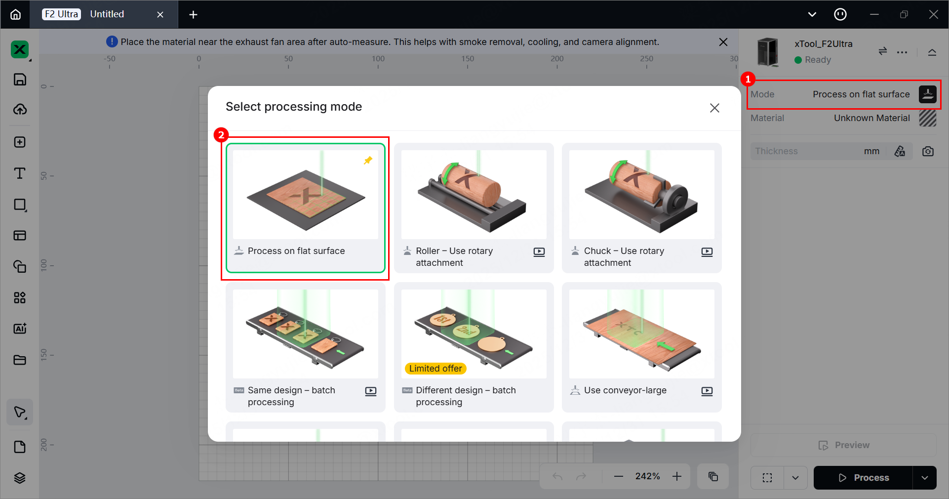
(1) In the right panel of the page, click the current processing mode, and then select Process on flat surface.
(2) Click Unknown Material, select a desired material, and click Apply.
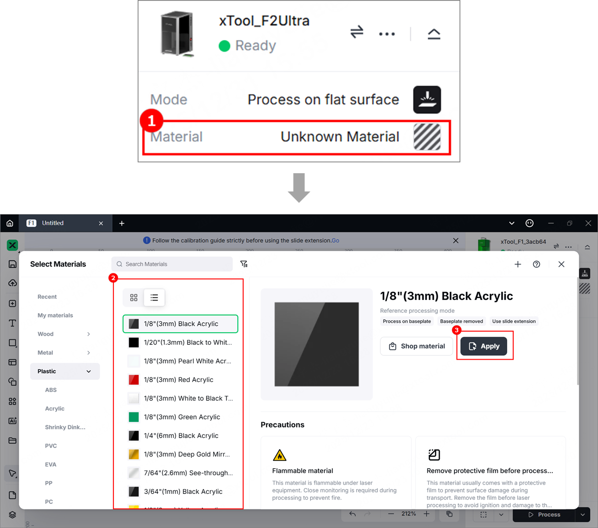
Note: The recommended parameter settings can achieve the best results only when using xTool materials. For third-party materials, it is recommended that you conduct a material test array on your own first to obtain the desired effects and parameters. Meanwhile, make sure that the materials are free from moisture or contamination, as these factors can significantly affect processing quality.
4. Set the laser focus
💡 For optimal cutting results, set the focal point at the midpoint of the material’s thickness.
- Example: To cut 6 mm basswood in a single pass, set the focal point 3 mm below the surface.
- Procedure: First, set the focus using a 3 mm thick material. Without changing the focus setting, replace it with the 6 mm basswood to be cut.
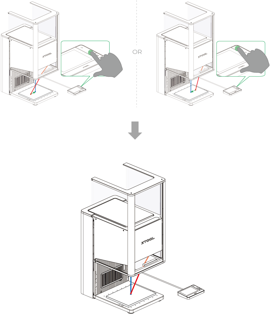
Hold down on the Up/Down button to move the laser module up and down. When the red and blue light spots coincide, the focus is successfully set.
Note:
- If you press and hold the Up button for laser module, the laser module will move up, and the red light spot will move toward the left.
- If you press and hold the Down button for laser module, the laser module will move down, and the red light spot will move toward the right.
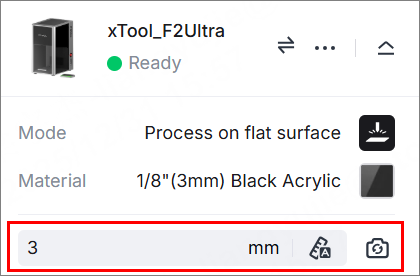
After focusing, the measured material thickness is displayed in the material thickness field on the right side of xTool Studio.
5. Design objects for processing
(1) Use the tools on the left side of the canvas to create objects. You can import images, insert shapes, enter text, or draw vector graphics.
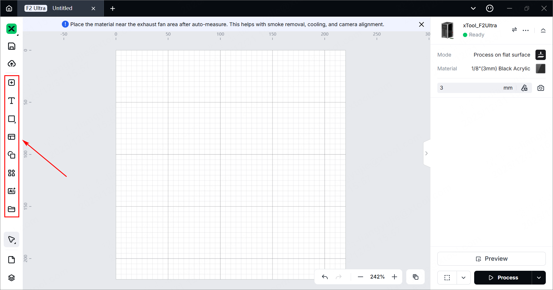
Note: xTool Studio supports importing the following image formats: SVG, DXF, JPG, JPEG, PNG, and BMP.
(2) After selecting the objects, use the toolbar to make further adjustments.
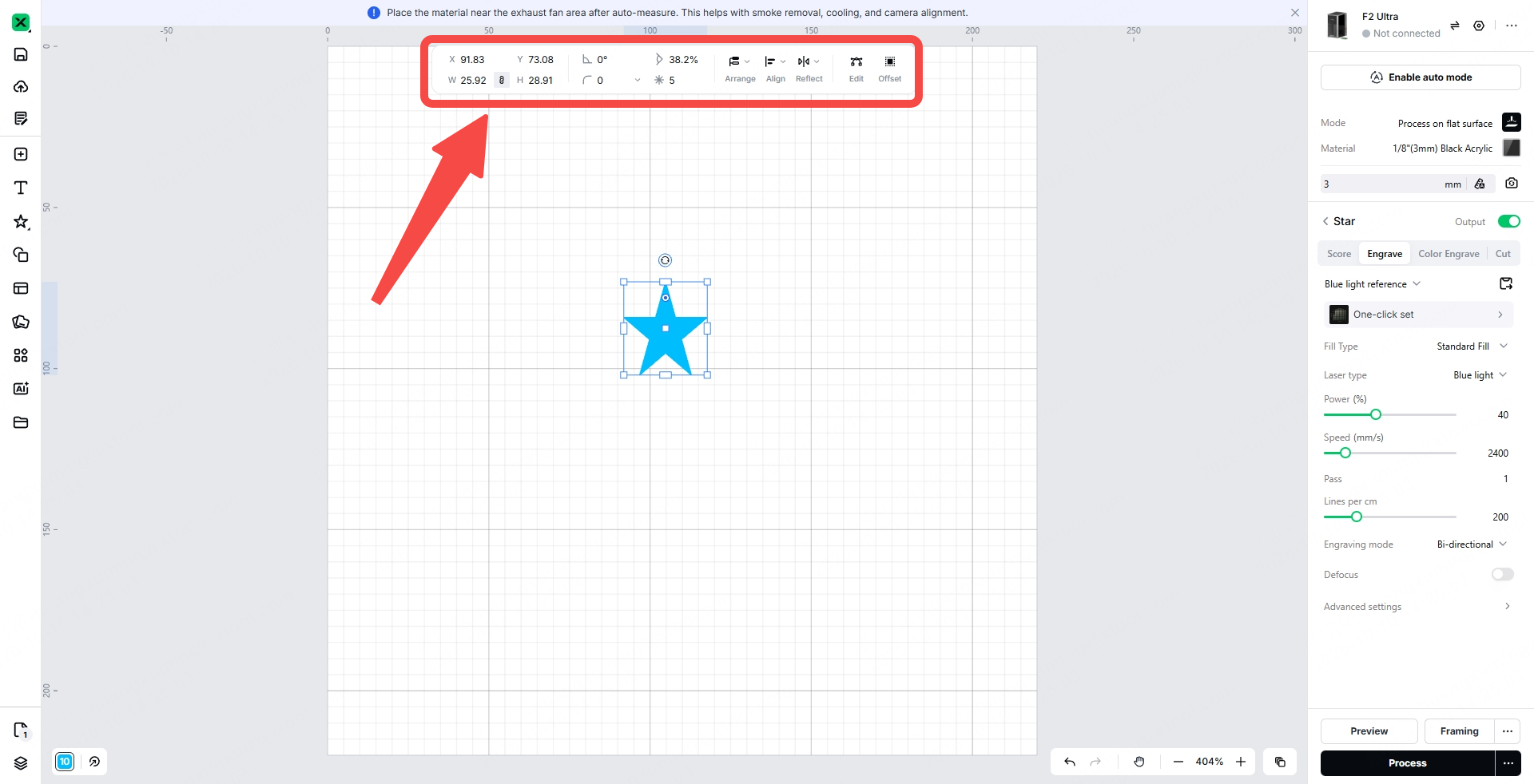
6. Set processing parameters
Select objects on the canvas and set their parameters in the right panel.

Processing type
- Image - Engrave/Color Engrave: The laser beam interacts with the material surface to change its color. By creating different shades of color, xTool F2 Ultra reproduces the image on the material.
- Vector - Score: The laser beam follows the vector path, engraving lines on the material.
- Vector - Engrave: The laser beam scans and fills the entire area enclosed by the vector path, engraving the vector on the material with monochromatic fillings.
- Vector - Color Engrave: The laser beam scans and fills the entire area enclosed by each vector path, engraving different vectors in different colors.
- Vector - Cut: The laser beam cuts the material along the vector path.
Note: Set parameters for each object. Otherwise, objects without parameters may not be processed.
Note:
- Parameter options differ between bitmap objects and vector objects. You can select multiple objects of the same type and set parameters for them at the same time.
- For more information on parameter settings, see atomm.com/easyset.
7. Set the processing path
(1) Click ... next to Process in the bottom-right corner and set the processing path.
- Auto planning: xTool Studio automatically plans the processing path based on intelligent algorithms.
- User defining: Manually set the processing paths for some objects.

(2) Enable or disable Evade smoke. When enabled, the device follows a processing path that is less affected by smoke.
Note: Enable this feature when scoring materials that produce heavy smoke, such as wood and corrugated paper. Otherwise, the smoke may block the laser beam and interfere with laser processing.
(3) Click the Set Start Point button to adjust the start point and direction of a single closed-path vector. (4) Choose either Auto detect holes and contours or Use existing kerf direction as needed. (5) Enable or disable Remove Overlapping Lines. You can adjust the Overlap spacing.
8. Preview the processing area
You can use framing to preview the processing area on the material. During framing, the laser dots move along the boundary of the objects to be processed. Perform the following steps to start framing. (1) Click ... next to Framing in the bottom-right corner of the xTool Studio window and set the framing parameters.

In Rect mode, the laser dots move along the rectangular boundary of the objects to be processed.
In Outline mode, the laser dots move along the outlines of the objects to be processed.
In Polygon mode, the laser dots move along the polygonal path defined by the vertices of the objects to be processed.
(2) Click Framing in the bottom-right corner of the xTool Studio window. The laser dots will move along the boundary of the objects to be processed, allowing you to preview their processing area on the material.
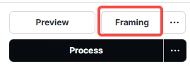


By default, xTool F2 Ultra performs framing for all elements to be processed. To preview the boundary of specific elements, select one or more elements on the xTool Studio canvas before starting framing. The laser dots will move along the boundary of the selected elements, as shown in the following images.
- Default framing:
- Selected element framing:
9. Start processing
(1) In the bottom-right corner of the xTool Studio window, click Process.

(2) Click Preview Processing Path and to preview the processing path.


(3) Close the protective enclosure. In the bottom-right corner of the xTool Studio window, click Start.
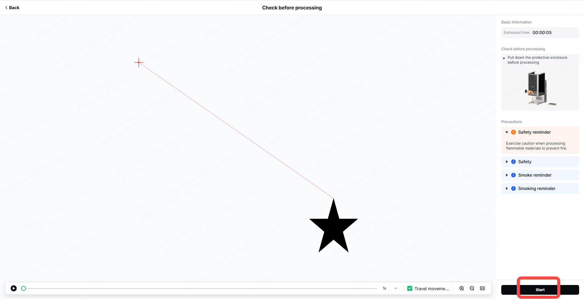
(4) When the xTool Studio window shows Ready, press the XTOOL Start/Stop button on the touchscreen controller to start processing.
⚠️ Safety reminder: During laser processing, keep the protective enclosure closed or wear a pair of goggles that can shield laser beams of 445 ± 15 nm and 1064 ± 5 nm wavelengths.
More information
xTool F2 Ultra Example Project
(xTool Studio) Process a Curved Material with xTool F2 Ultra
(xTool Studio) Start Laser Embossing with xTool F2 Ultra
(xTool Studio) Start Color Engraving with xTool F2 Ultra
(xTool Studio)Start Offline Processing with the Touchscreen Controller
(xTool Studio) Use the Conveyor to Process a Large Material with xTool F2 Ultra
(xTool Studio) Use the Conveyor for Same Design Batch Processing with xTool F2 Ultra
(xTool Studio) Use the Conveyor for Different Design Batch Processing with xTool F2 Ultra
(xTool Studio) Use Rotary Attachment 3 (RA3) with xTool F2 Ultra
Use xTool F1 Ultra / F2 Ultra Series to Engrave a Screen in xTool Studio