To use the automatic conveyor feeder with xTool S1, the following requirements must be met.
Material requirements
- Materials are flat without warping edges.
- xTool S1 automatic conveyor feeder can transport hard materials, flexible and thin materials (such as kraft paper), as well as soft and thick materials (such as cork board and EVA foam board).
- To process a hard material, place it on the conveyor rails.
- To process a flexible and thin material, use the material pressing rod instead of the conveyor rails.
- To process a soft and thick material, stick PET tape on its back before placing it on the conveyor rails.
- When a material is placed on the conveyor rails, ensure that the hanging part out of the rails is no longer than 30 cm.
- The conveyor feeder can support 8 pairs of conveyor rails in total. You can add at most 6 pairs of conveyor rails to the convey feeder (3 pairs on each side). With different numbers of conveyor rails installed, the supported material length varies.
Number of pairs of conveyor rails (An equal number of conveyor rails are installed on each side) | Conveyable width (W) and thickness (H) | Conveyable length (L) (including 30 cm of suspended length out of the rails) | Processing length (P) |
|---|---|---|---|
2 pairs (original conveyor rails) | 65 mm ≤ W ≤ 545 mm 0 mm < H ≤ 14 mm | 0 mm < L ≤ 1070 mm | 0 mm < P ≤ 820 mm |
4 pairs | 0 mm < L ≤ 1690 mm | 0 mm < P ≤ 1440 mm | |
6 pairs | 0 mm < L ≤ 2310 mm | 0 mm < P ≤ 2060 mm | |
8 pairs | 0 mm < L ≤ 2930 mm | 0 mm < P ≤ 2680 mm |
Device requirement
To process materials that are too long for xTool S1, you need to use xTool S1 with the automatic conveyer feeder and the riser base that supports the conveyer feeder.
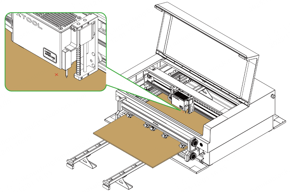
1. Place the material
Note: The following steps show you how to place a hard material on the conveyer feeder. For more information on how to place a flexible and thin material or a soft and thick material, see the User Guide for xTool S1 Automatic Conveyor Feeder.
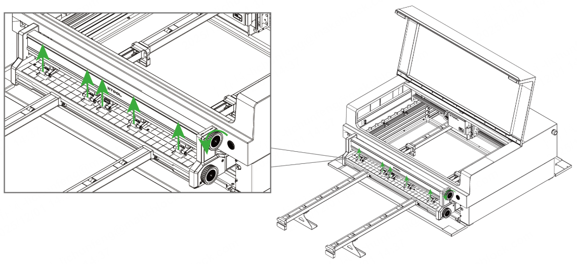
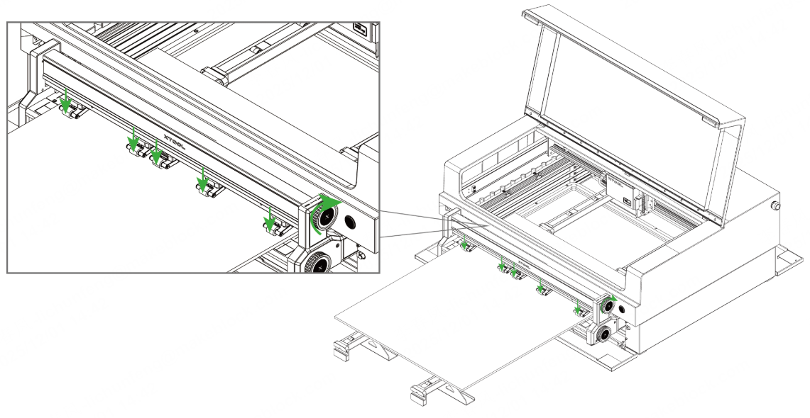
(1) Turn the upper knob counterclockwise to raise the pinch rollers.
(2) Place the material into the conveyor feeder. Ensure that the side edges of the material are parallel to the vertical grid lines and do not intersect with the pinch roller.
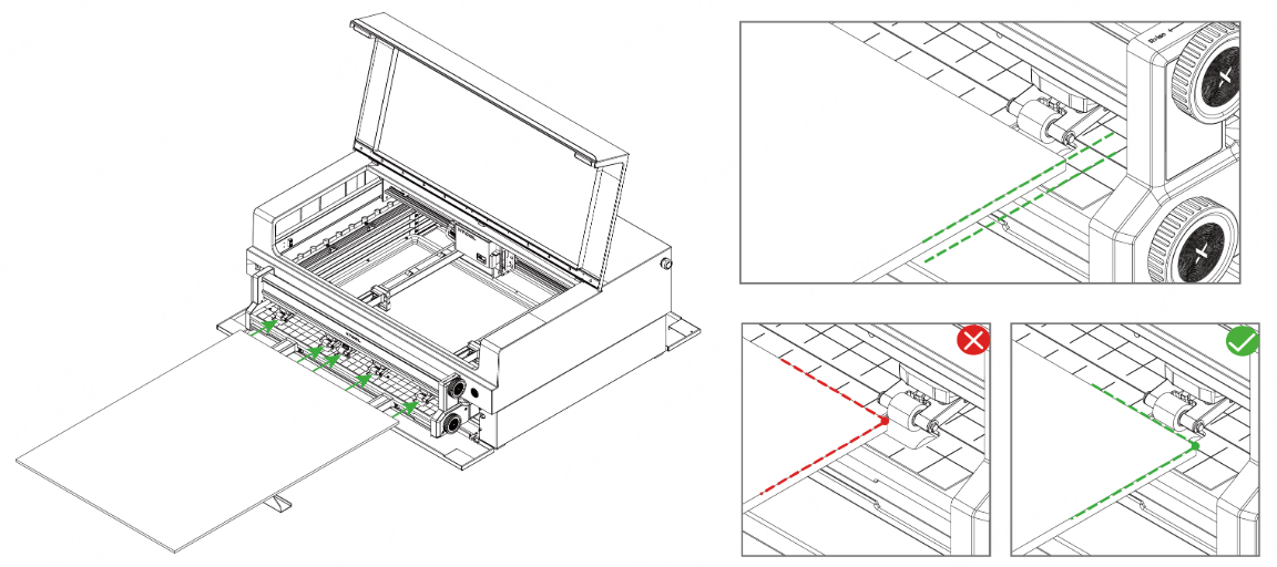
- If the side edges of the material are not parallel to the vertical lines of the grid, the processing pattern may come out skewed.
- If the side of the material intersects with the pinch rollers, the material may deviate from the original conveying track due to the squeezing of the pinch rollers.
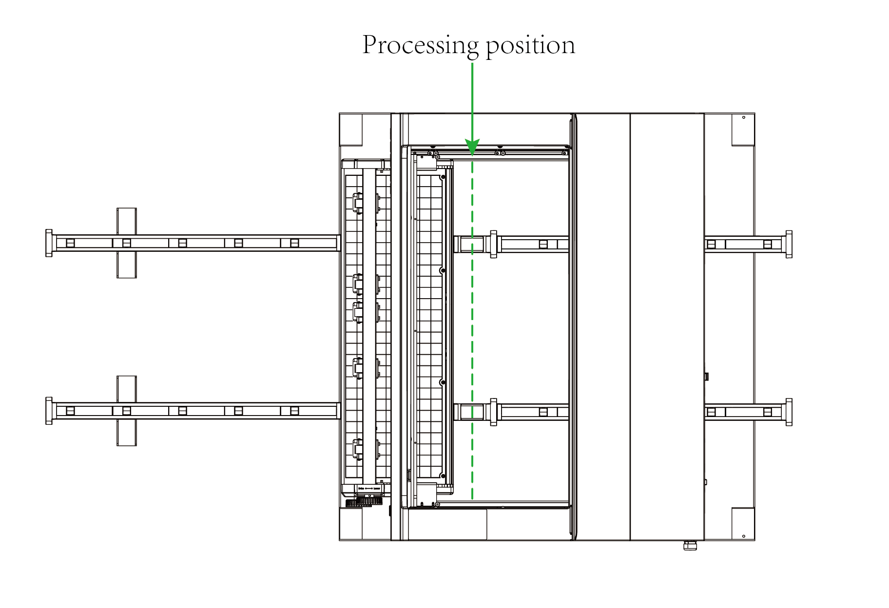
- When using the conveyer feeder, the laser module works only in the area above the short rails.
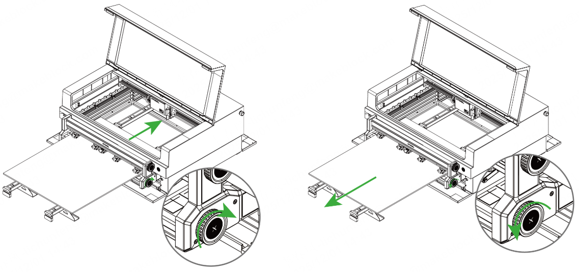
(3) Turn the upper knob clockwise to lower the pinch rollers to press the material in place.
- Do not set the pressure of the pinch rollers too high, or the conveyor feeder may fail to work properly.
- For how to set a proper pressure level, refer to "Appendix ––Pressure levels recommended for common materials".
You can use the lower knob to slightly adjust the position of the material if needed. Rotate the lower knob clockwise to move the material forward, and counterclockwise to move the material backward.
2. Open or create a project
You can open a project to start processing or create a new project. If you create a new project, you need to design patterns and set parameters from scratch.
- Open a project
On the home screen of xTool Studio, click Open. In the pop-up window, select the desired file and click Open.
Note: The project file can contain information such as processing patterns, processing modes, and processing parameters. However, if the machine model, processing mode, or material thickness used in the project varies from the current situation, you need to reset the corresponding parameters.
- Create a new project
On the home screen of xTool Studio, click + New Project.
3. Select the processing mode and material name
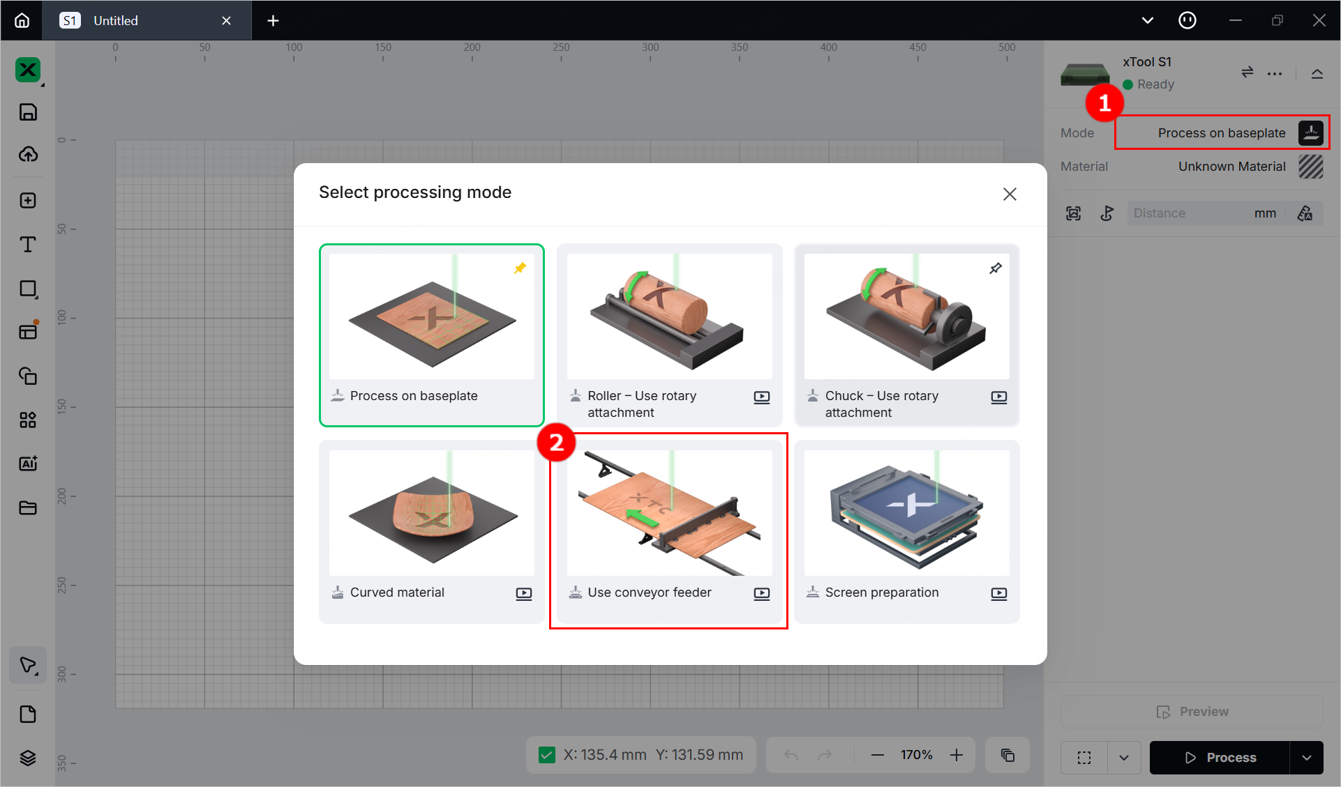
(1) In the right pane of the page, click the name of the current processing mode, and then select Use conveyor feeder.
(2) Click Unknown Material, select the desired material, and click Apply.
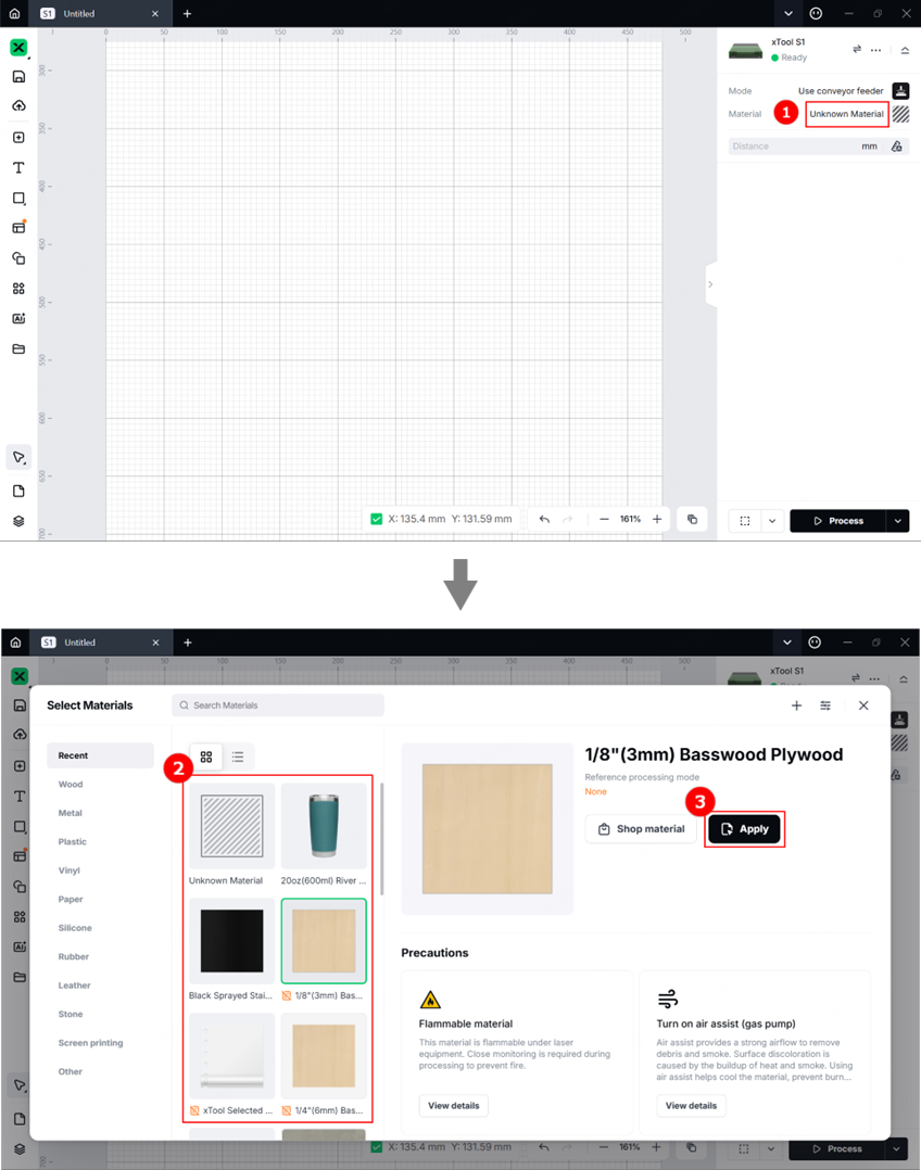
Note: After you select a material from the material list, the software will automatically set parameters for laser processing. The default settings apply to xTool materials. You can adjust the settings based on your needs.
(3) Turn on or off Laser module position based on your need.
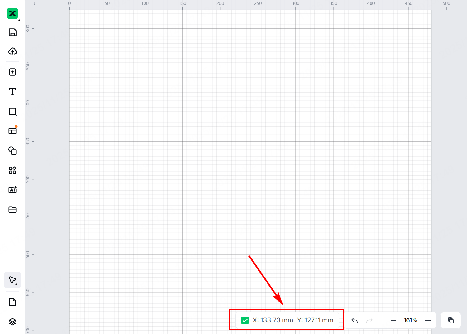
Note: If you turn on Laser module position, the software will display the position of the laser module in real time. The red cross in the canvas indicates the laser module, and the coordinates of the laser module are shown near Laser module position.
4. Set the laser focus
xTool S1 has a distance sensor, which can measure the distance between the laser module and the material surface. You can also manually measure and calculate the distance between the laser module and the material surface, and input the obtained values into the software.
During processing, xTool S1 will perform auto-focus based on the Distance parameter.
- Auto meausre
(1) Move the laser module over the material. Ensure that the locating spot falls on the surface of the material.
(2) In the right pane of the page, click the Auto-measure icon, and xTool S1 will automatically measure the distance from the laser module to the material surface.
Note: Before auto-measure, ensure that the probe of the distance sensor is not extending.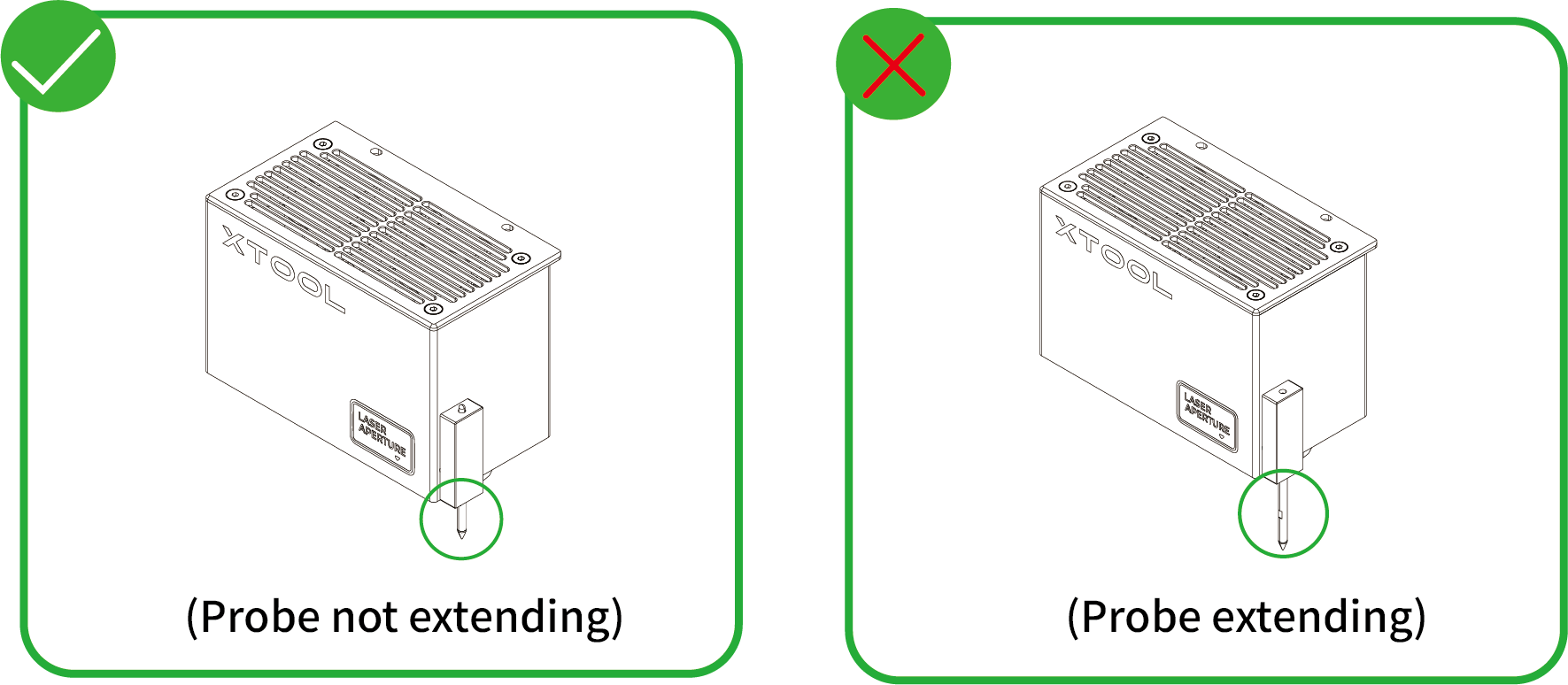
- Manual measure
(1) Use a ruler to measure the distance from the surface of the material to the top of the laser module.
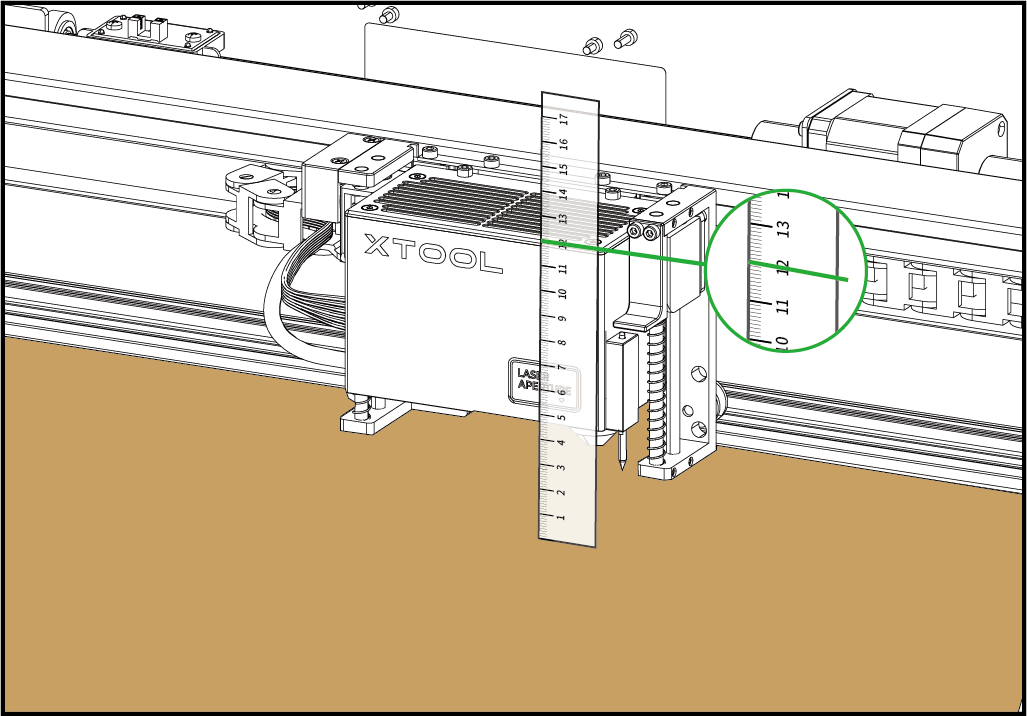
(2) Subtract 100 mm (3.937 inches) from the measured value from step (1), and input the calculated value as Distance.
5. Design objects for processing
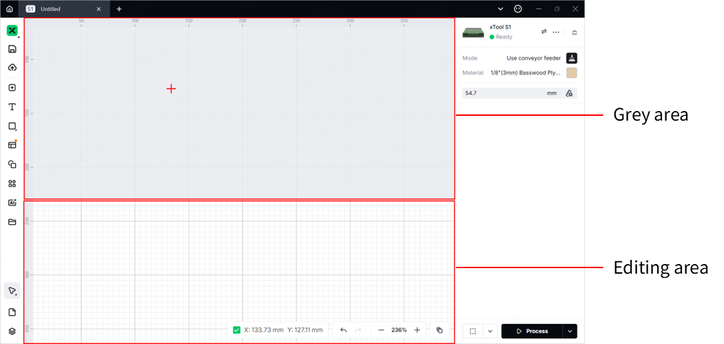
- About the canvas
The canvas is divided into two parts: the grey area and the editing area. The grey area corresponds to the area inside xTool S1 where the laser module does not go during processing. The laser module works only in the area above the short rails. Therefore, do not place elements in the grey area, or the elements will not be processed.
(1) Use the tools to the left side of the canvas to create objects. You can import images, insert shapes, enter text, or draw vector graphics.
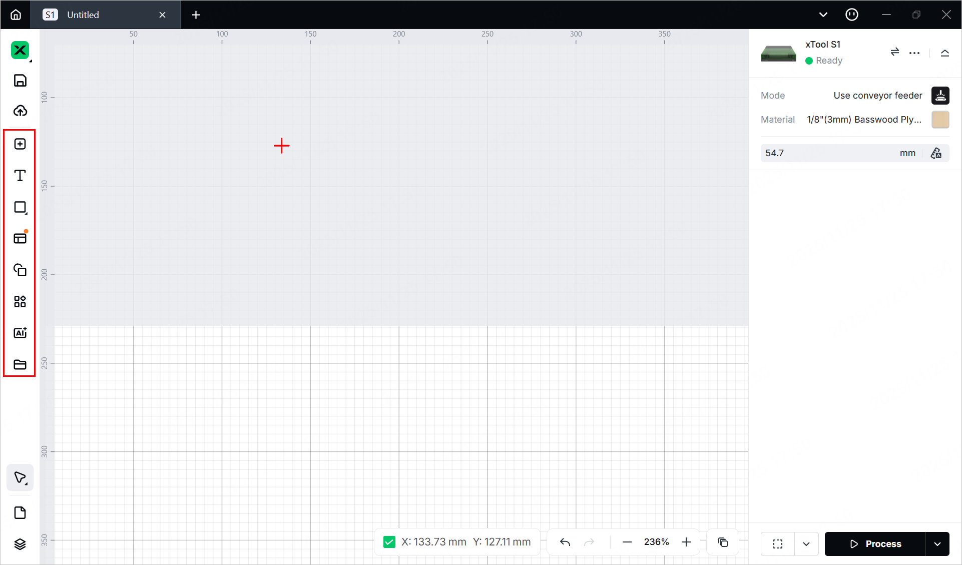
Note: xTool Studio supports importing the following image formats: SVG, DXF, JPG, JPEG, PNG, BMP, etc.
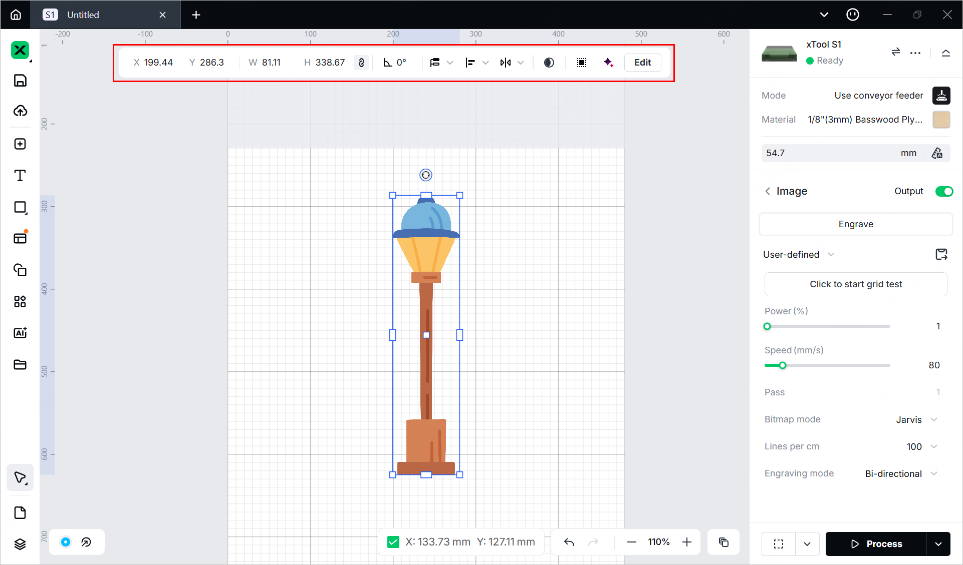
(2) Select the objects to further edit them using the tools above the canvas.
6. Set parameters for processing
Select objects on the canvas first and set parameters for them.
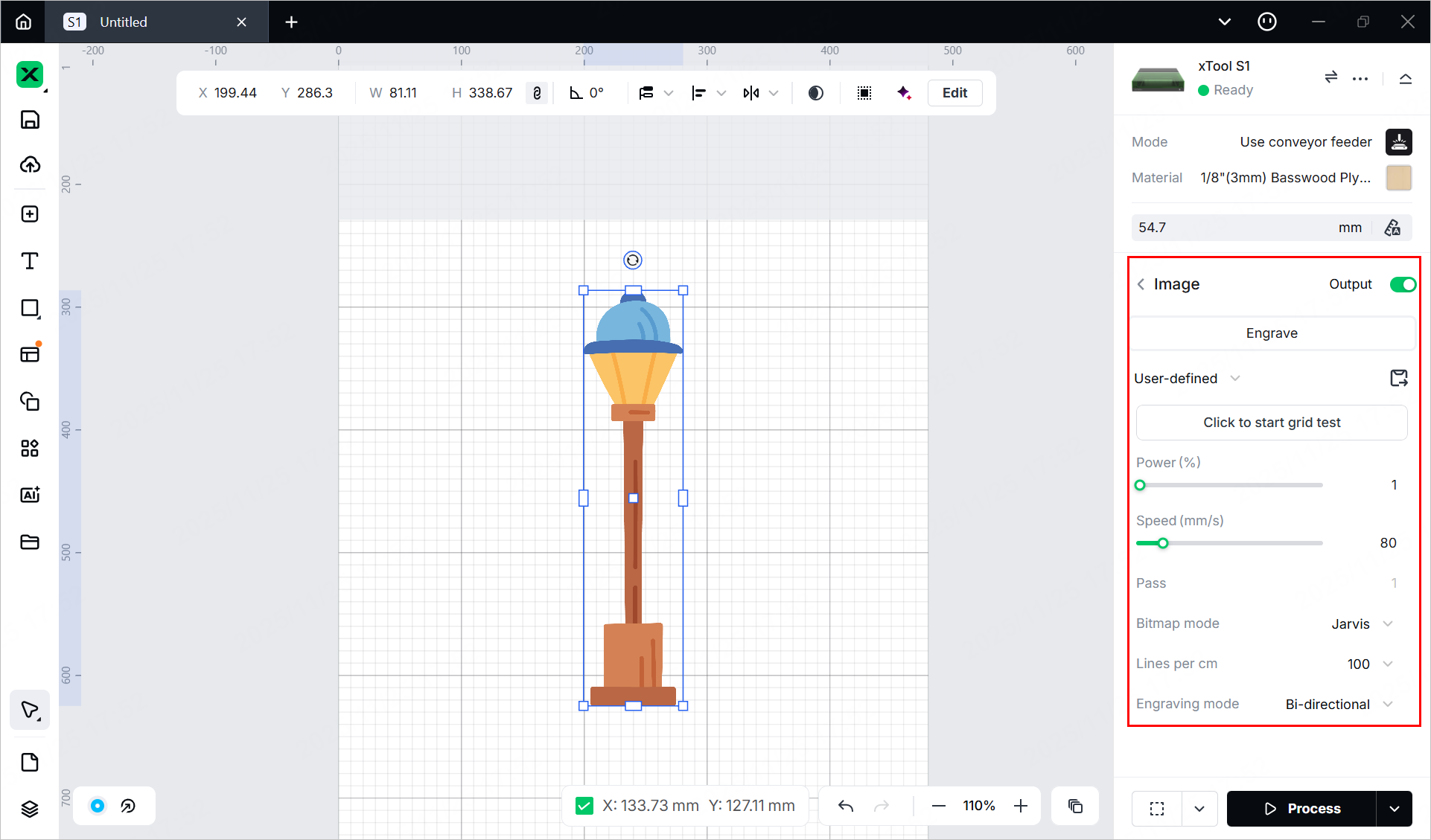
You need to set parameters for every object. A missed object may fail to be processed.
The parameters that can be set for bitmap objects and vector objects are different. You can select multiple objects of the same type and set parameters for them at once.
For more information on parameter settings, see atomm.com/easyset.
7. Preview the processing area
You can preview the processing area on the material by framing. Framing means laser dots walk along the border of the processing objects on the material. Take the following steps to start framing.
(1) Click in the bottom-right corner of the software and set parameters for framing.
Note: You can click the arrow buttons to control the movement of the laser module. The other three parameters allow you to configure how the laser module moves with every tap on an arrow button.
XY speed (mm/s): The moving speed of the laser module in X and Y directions.
XY distance (mm): The moving distance of the laser module with each tap on an XY arrow button.
Z distance (mm): The moving distance of the laser module with each tap on a Z arrow button.
(2) Depending on the laser module you use, wear a pair of safety goggles that can shield your eyes from the laser beams (blue light laser beams: 455 nm; infrared laser beams: 1064 nm).

(3) Click Framing in the software and press the button on xTool S1 to start framing. The laser spot will move along the boundary of the processing pattern on the material so that you can preview the processing area.
(4) After the framing is complete, click Framing completed in the software. If the area is not ideal, you can adjust the material position or adjust the element positions in the software, and then preview the processing area again.
8. Start processing
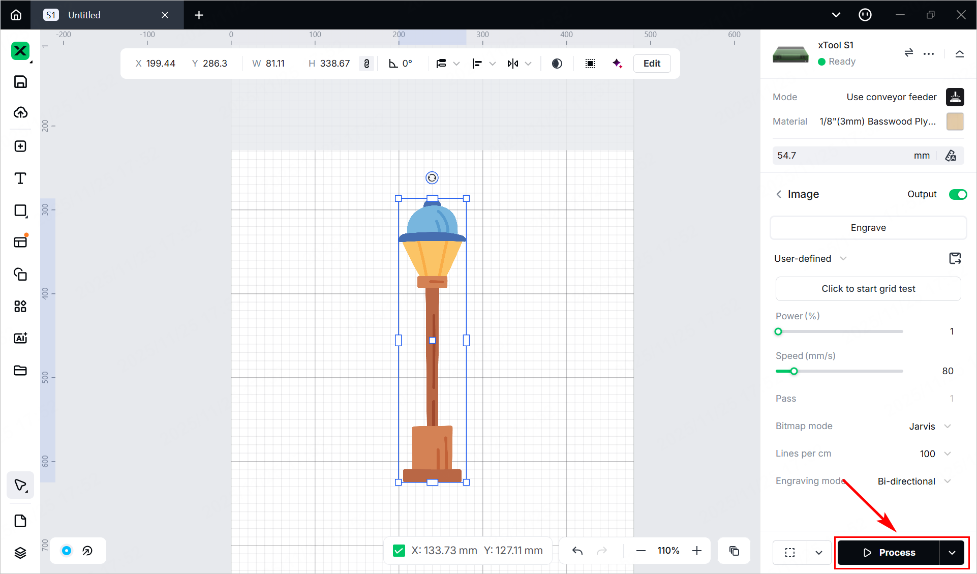
(1) In the bottom-right corner of the software, click Process.
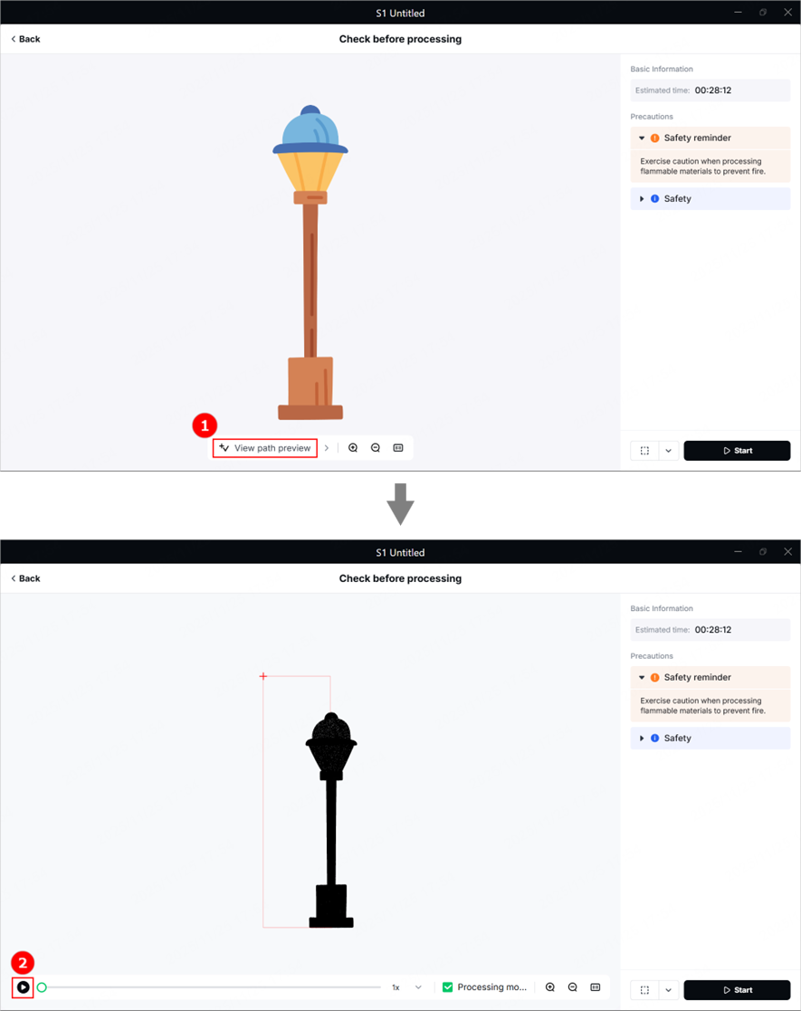
(2) Click View path preview and to preview the processing path.
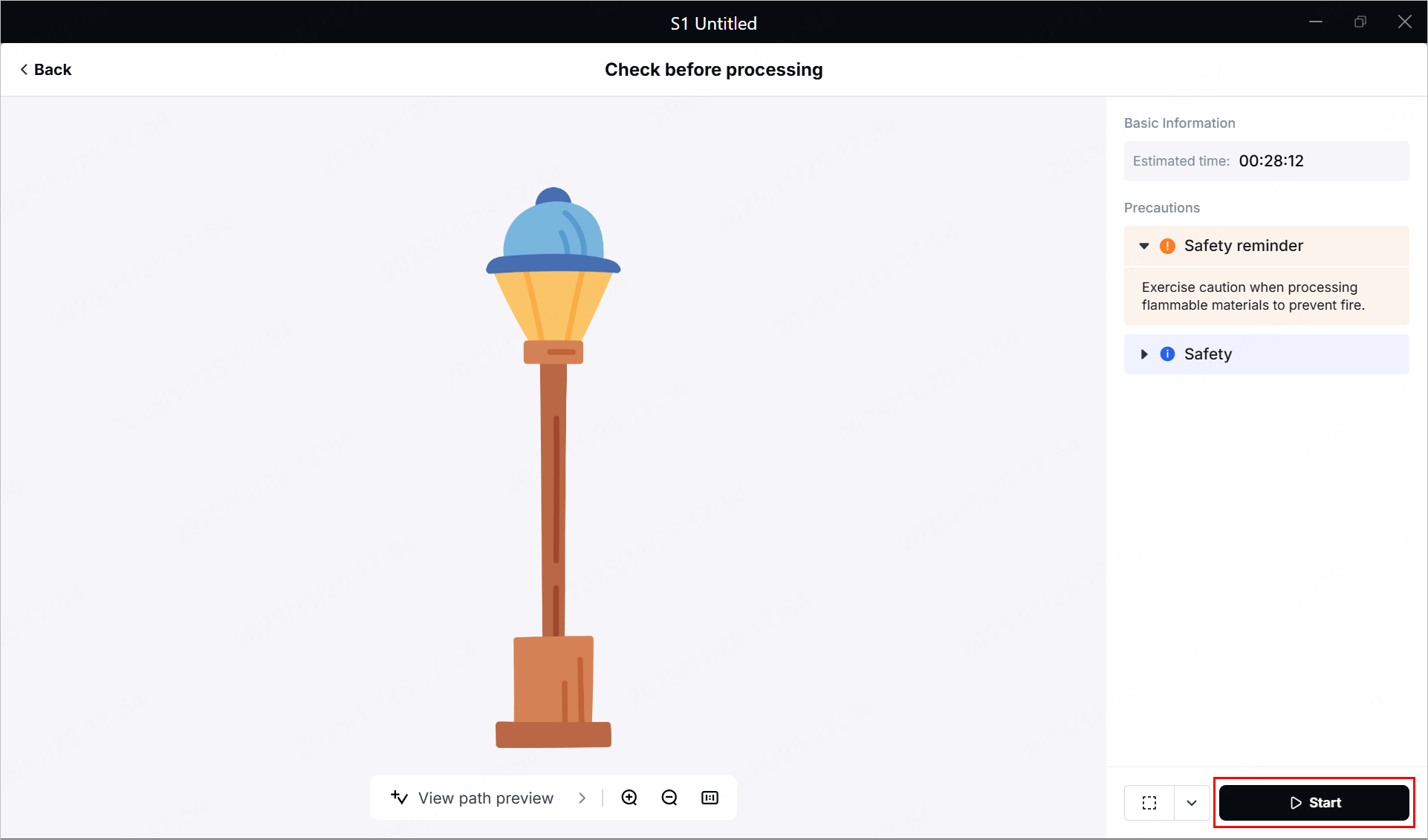
(3) In the bottom-right corner of the software, click Start.
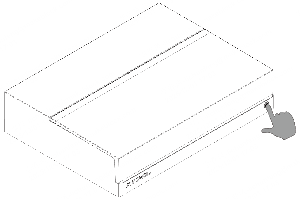
(4) Wear a pair of laser safety goggles. Then, close the lid of xTool S1 and press the button to start processing.