Prepare for installation
Power supply
xTool MetalFab Laser Welder 1200W requires a 200 V – 240 V AC power supply, and works at a rated power of 4200 W. An individual branch circuit with a current-carrying capacity of 25 A or above is recommended.
Requirements on electrical facilities vary with power cables. Please consult a qualified electrician before installing the device to ensure that the device is installed in accordance with local electrical codes.
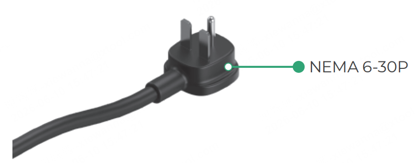
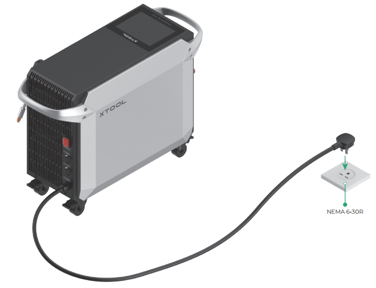
US standard
| · Use a NEMA 6-30R outlet (or 6-50R for some versions) Note: Some product versions may come with a 6-50P plug. Please select a proper power outlet depending on the plug type. |
EU standard
| Choose one of the following methods: |

Note: For the electrical requirements of other types of power cables in other regions, see Power Requirements for MetalFab Products in Different Countries and Regions.
■ Consult a professional electrician beforehand to ensure that the device is installed in accordance with local electrical codes.
■ Ensure that the current-carrying capacity of your circuit meets the requirements. Do not connect the product to a standard household circuit, as it may damage both the product and the circuit.
■ Ensure that the welder is powered separately. Do not use it with other high power equipment on the same circuit.
■ To ensure safety, it is recommended that you install a 25 A air circuit breaker between the power supply and xTool MetalFab Laser Welder 1200W.
Workroom
Ensure that the workroom is well-ventilated.
Shielding gas
xTool MetalFab Laser Welder 1200W requires the use of shielding gas. Supported gas types include nitrogen and argon, and the gas purity must be over 99.99%.
Different processing types have different requirements on gas supply:
Processing type | Gas flow/pressure requirement | Necessary accessory |
Laser welding | Flow rate: 15 L/min – 30 L/min | Gas flow meter |
Laser cleaning | Gas pressure: 100 kPa – 200 kPa (14.50 PSI – 29.01 PSI) | Gas pressure regulator + gas flow meter |
Laser cutting | Gas pressure: 800 kPa – 1200 kPa (87.02 PSI – 116.03 PSI) | Gas pressure regulator |
Install xTool MetalFab Laser Welder 1200W
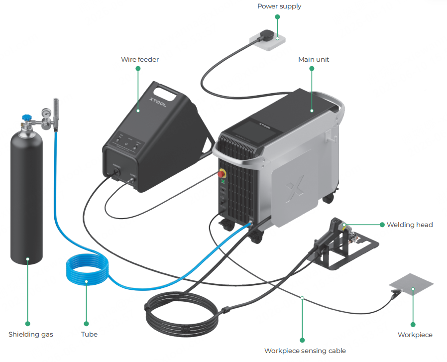
Cabling diagram
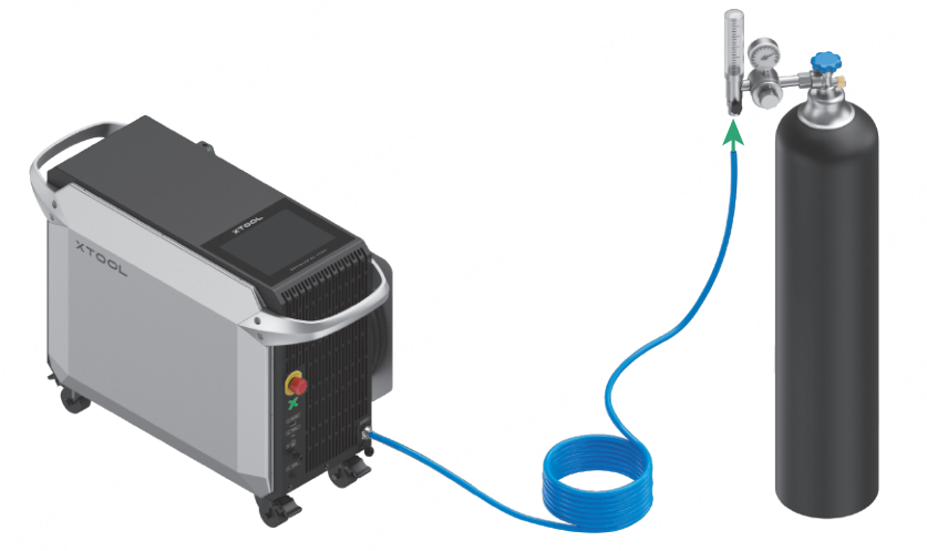
The following picture shows the cabling diagram of xTool MetalFab Laser Welder 1200W. Please follow the detailed step-by-step instructions to complete the installation.
Installation
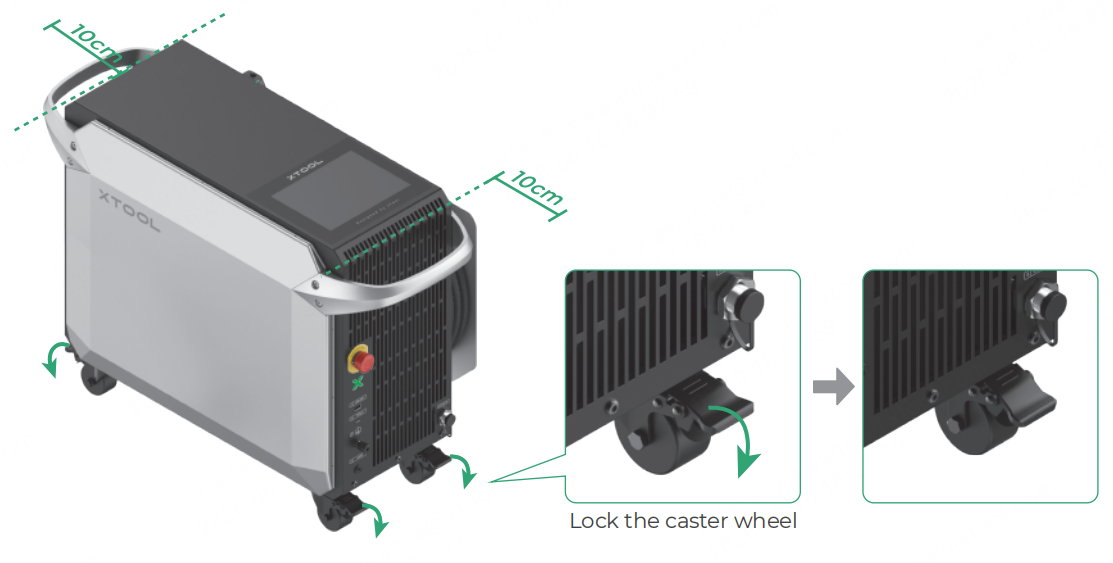
1. Place the main unit
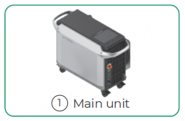
Place the main unit in a proper place, leaving a gap of no less than 10 cm at the front and back to ensure good ventilation and heat dissipation. Step on the pedals of the four caster wheels to lock the main unit in position.
2. Connect the shielding gas cylinder
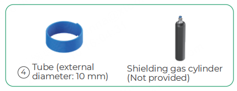
(1) Insert one end of the tube into the shielding gas inlet on the main unit.
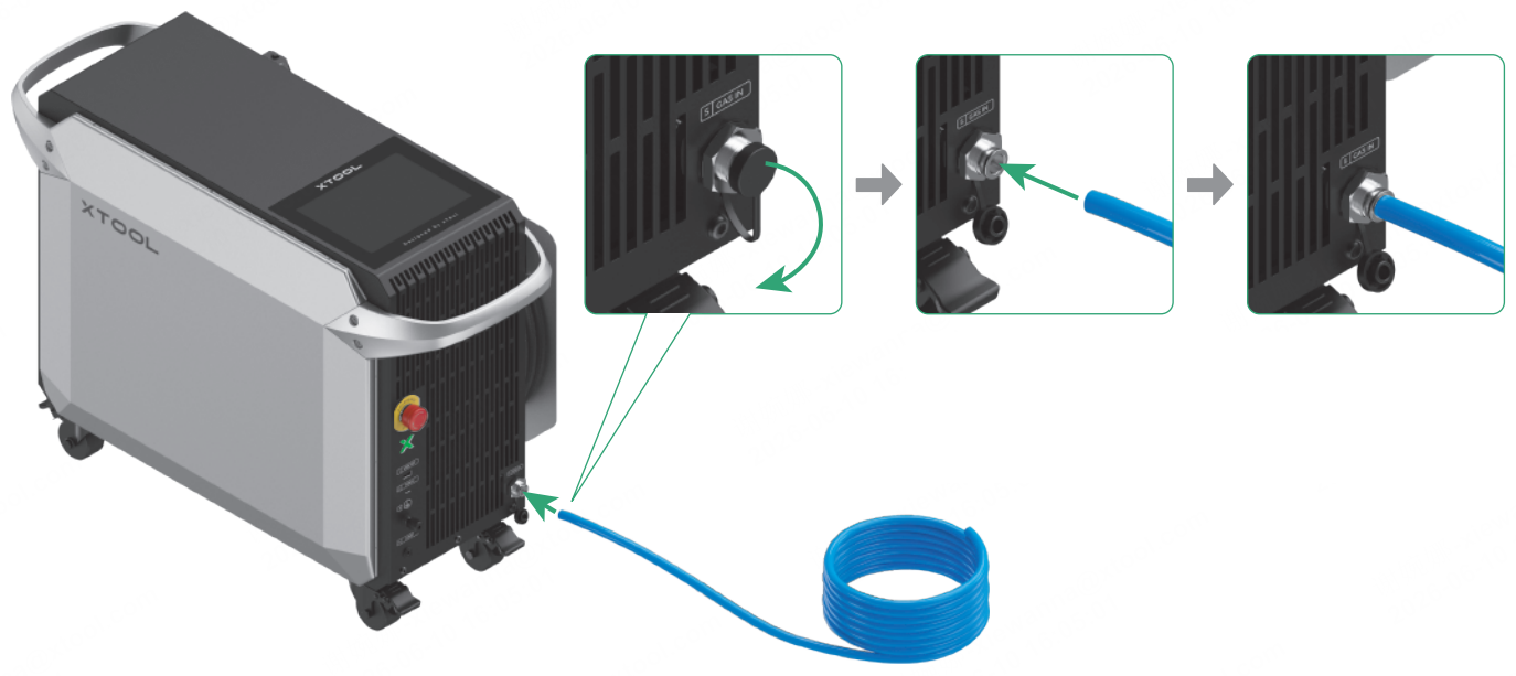
■ After inserting the tube, attempt to pull it out. If the tube remains securely in place, it is connected properly.
■ To remove the tube, push and hold the collet of the shielding gas inlet and pull out the tube.

(2) Install a gas regulator on the shielding gas cylinder (or gas generator).
(Installing a gas flow meter on a cylinder is used as an example.)
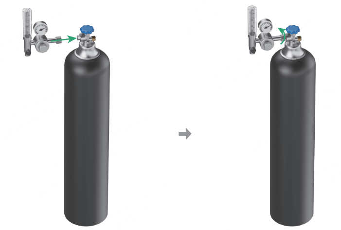
(3) Connect the other end of the tube to the cylinder (or gas generator).
3. Place the welding head
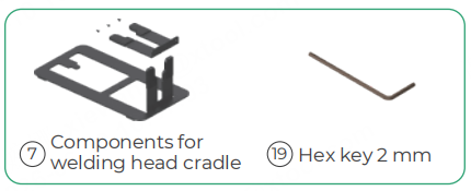
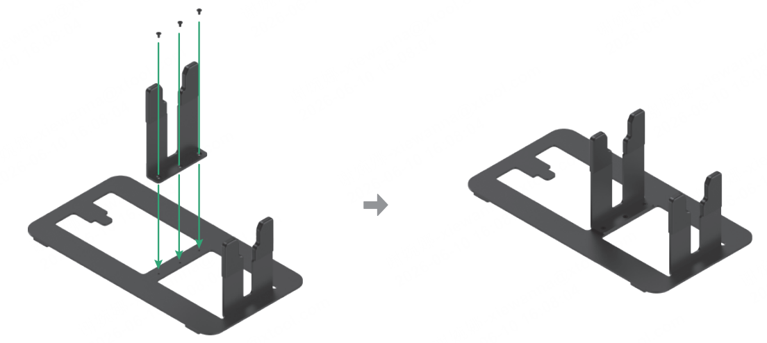
(1) Assemble the welding head cradle.
(2) Take the welding head off the main unit and release the welding head cable from the reel. Place the welding head on the cradle, ensuring that the welding head cable is not twisted.
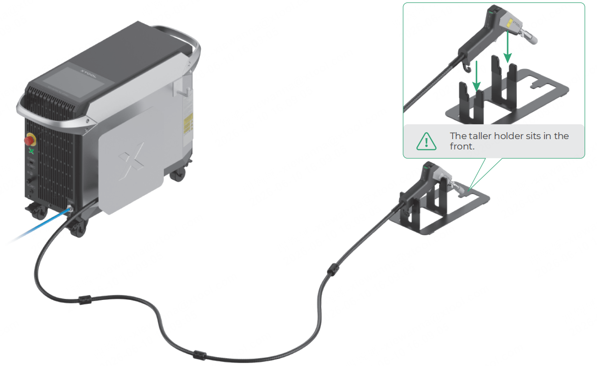
Note: Do not pull the cable forcefully when taking the welding head off, as this can damage the optical fiber.
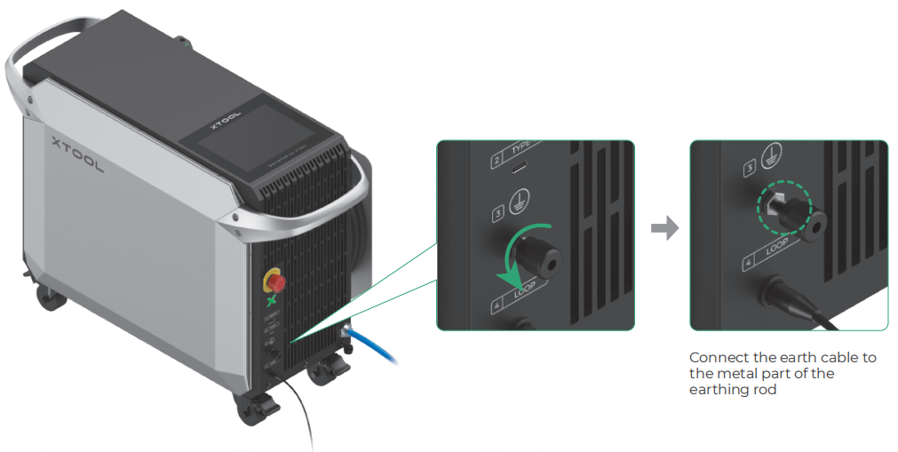
4. Connect the workpiece sensing cable
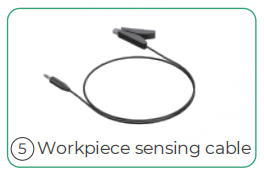
Insert the connector end into the port for the workpiece sensing cable, and attach the clamp to the worktable for now.
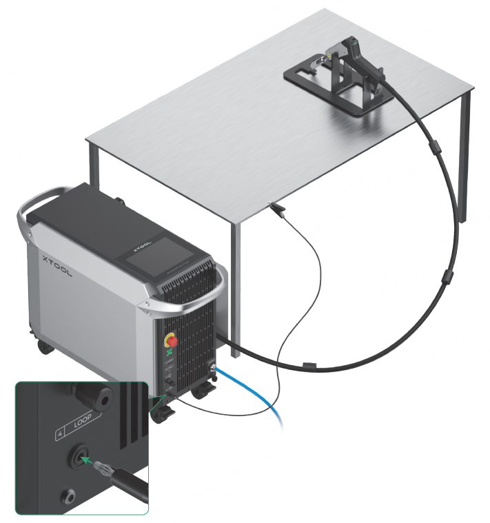
The workpiece sensing cable is used to connect the main unit with the workpiece, forming a safety interlock loop. The cable clamp needs to be connected to the workpiece before welding. During welding, when the welding head is in contact with the workpiece, the safety interlock loop will be closed and allow laser emission.
5. Connect to a power supply
■ Ensure that the current-carrying capacity of your circuit meets the requirements. Do not connect the product to a standard household circuit, as it may damage both the product and the circuit.
■ To ensure safety, it is recommended that you install a 25 A air circuit breaker between the power supply and xTool MetalFab Laser Welder 1200W.
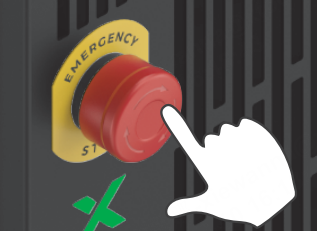
6. Check the emergency stop button
Ensure that the emergency stop button is released. If it is pressed, rotate it to release it.
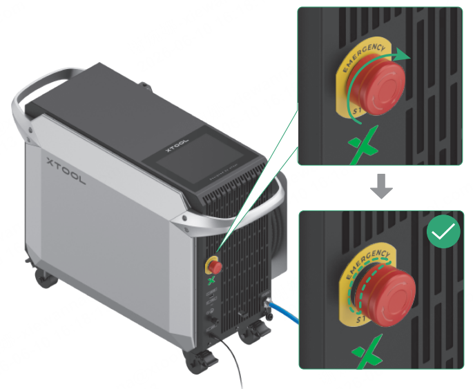
If an emergency occurs, press the emergency stop button to shut off the machine.
After dealing with the emergency, rotate the emergency stop button to release it.
7. Insert the key
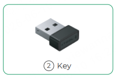
Insert the key into its designated port.
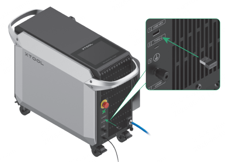
You can use the key either as an access-control key or a remote interlock connector.
Access-control key
Removing the key can disable the machine's processing and related functions.
Remote interlock connector
For detailed instructions, visit support.xtool.com/article/1367.
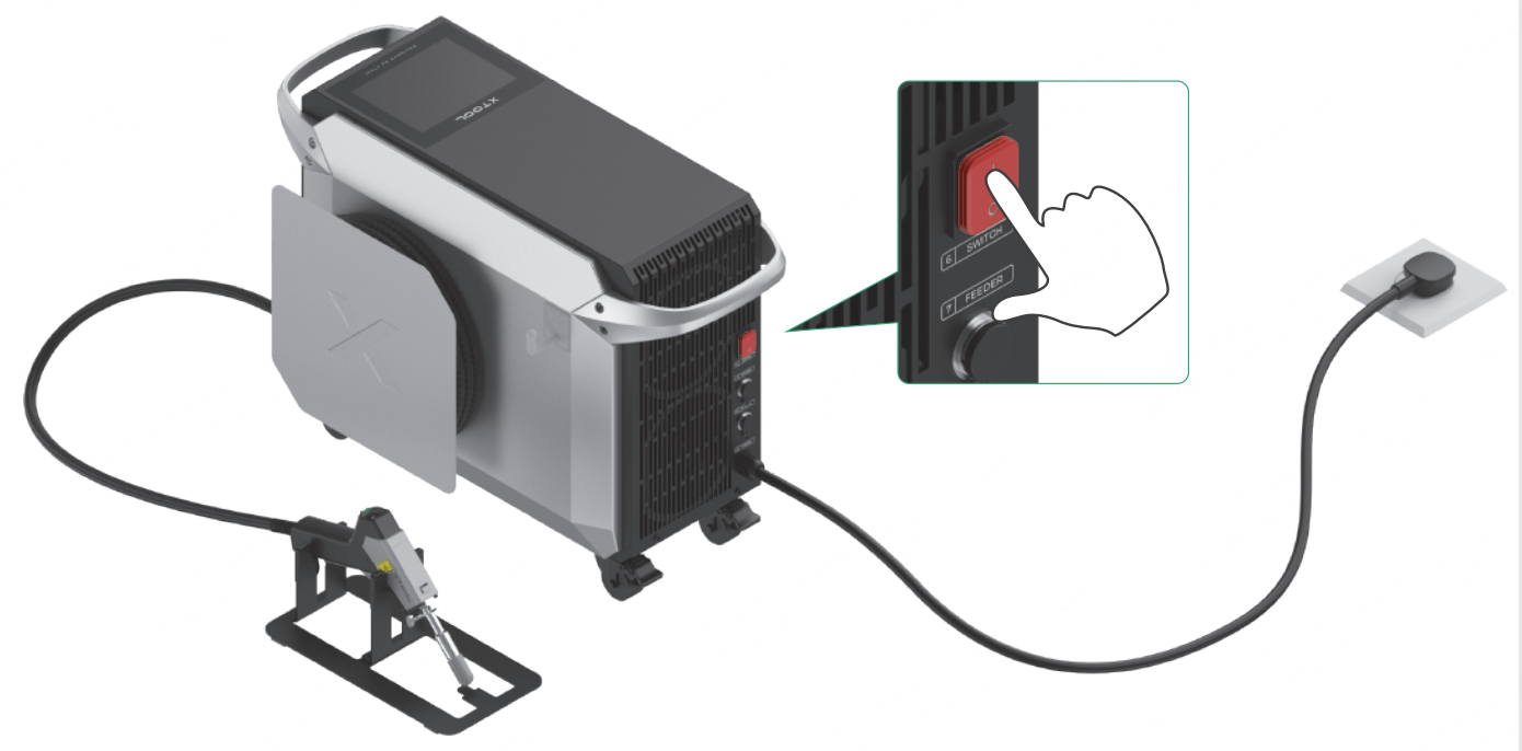
8. Power on
On the back panel of the main unit, turn on the power switch to power on the device.
Unlock the device
Note: Peel off the protective film from the touchscreen before you use it. Otherwise, the screen may display blurry.
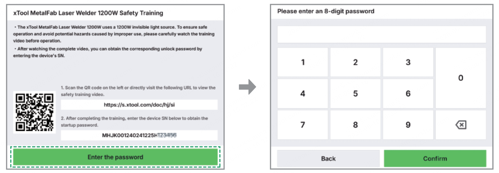
(1) The first time you turn on the device, you will see a QR code displayed on the touchscreen. Scan the QR code or visit s.xtool.com/doc/hj/si to watch the safety training videos.
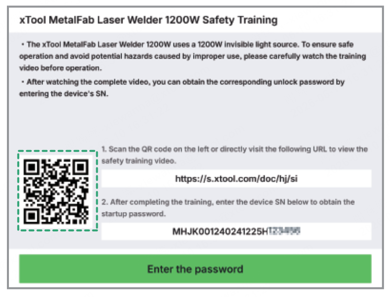
(2) After watching the video, input the serial number (SN) shown on the touchscreen to the web to generate an unlock password for your device.
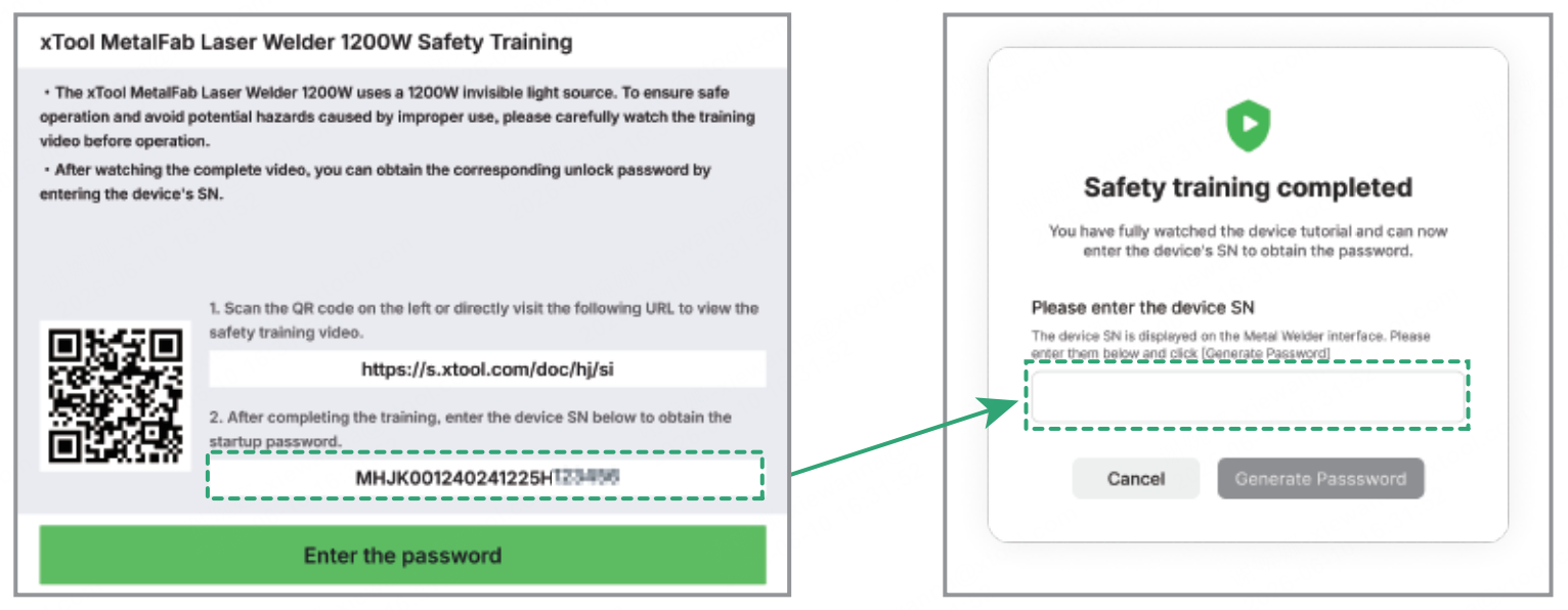
(3) On the touchscreen of your device, tap Enter the password. Then, enter the password generated to unlock your device.
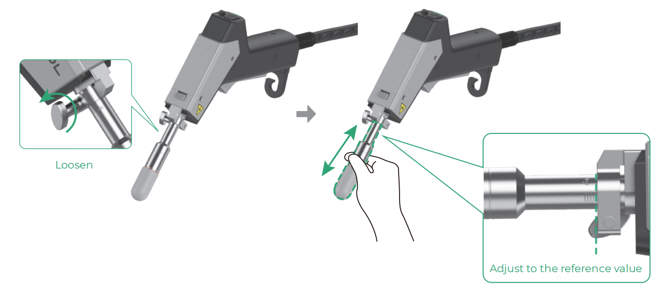
Calibrate the focus for the welding head
(1) On the home page of the touchscreen, tap System settings and check whether the Focus scale reference is the same as the actual value on the graduated tube. If the values are the same, no calibration is needed; if they are not, go to step (2).
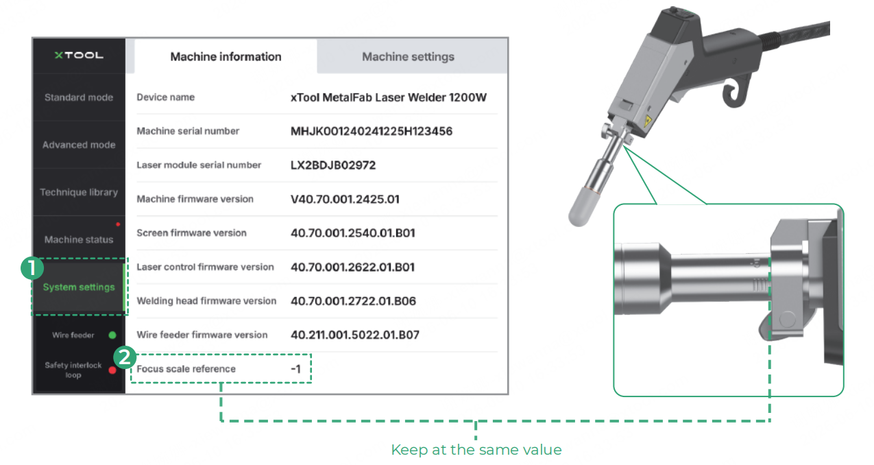
(2) Loosen the screw, and push or pull the graduated tube to adjust it to the reference value shown on the touchscreen.