This page describes how to operate an xTool machine with xTool Creative Space (XCS) V2.1 or later.
UI navigation
Homepage
On the homepage, you can:
1. Log in to your xTool account. Some functions, such as AImake and Cloud services, may require you to log in.
2. Go to the homepage. When you are using your Cloud space, you can click to go back to the homepage.
3. Open your Cloud space. To use the Cloud services, you need to log in to your xTool account.
4. Open the DesignFind official website, where you can find various projects created by xTool users. You can use them or get inspired.
5. Go to the xTool online shop to find more information about xTool machines and accessories.
6. Open a project from a local disk of your computer. Only XCS files are supported.
7. Click to create a project.
8. Click to open a recently created project.
9. Click to open a project that interests you on DesignFind.

Main toolbar
The main toolbar appears on all pages, allowing you to:
1. Go to the homepage
2. Create a project
3. See all the opened tabs, including the projects and xTool Projects page. You can create or close projects here. You can open a maximum of six projects at the same time.
4. Check for software updates (For macOS users, this function is on the system menu bar)
5. Set the software functions
6. Close XCS
7. Open the message center where you can find all the messages
8. View the task list
9. Minimize the window
10. Maximize or resize the window
11. Close the window

1. Minimize/resize/close the window
2. Go to the homepage
3. See all the opened tabs, including the projects and xTool Projects page. You can open a maximum of six projects at the same time.
4. Open the message center where you can find all the messages
5. View the task list
6. You can create or close projects here.

Project page
Toolbar

Main menu

File
- New: creates a new project file
- Open project: opens a project file for a local drive, supporting only XCS files
- Import image: imports an image file. Currently, XCS supports the importing of only JPG, JPEG, GIF, PNG, BMP, SVG, DXF, and WEBP files.
- Close: closes the current project tab
- Save: saves all the changes to the project
- Save as: saves the project as another file
- Rename: names the project
- Export as SVG: exports all the objects on the canvas as an SVG file
Edit
- Undo: cancels the last action
- Redo: performs the last canceled action again
- Copy: copies the selected object(s) on the canvas
- Paste: pastes the copied object(s) on the canvas
- Cut: cuts the selected object(s) on the canvas
- Delete:deletes the selected object(s) on the canvas
- Select All: selects all the objects on the canvas
Help
- Feedback: goes to the xTool support center
- User guide: opens the beginners' guide
Settings
Opens the XCS settings window
Left side bar

- Image: click to import an image. Currently, XCS supports the importing of only JPG, JPEG, GIF, PNG, BMP, SVG, DXF, and WEBP files.
- Text: click to enter a text
- Line, Rectangle, Circle: click to draw a line, rectangle, or circle
- Vector: click to draw a vector
- Shape: Click to open the shape material panel, and click to insert a shape
- Applications: applications such as grid array, circular array, material test array, code generation, and batch fill are collected here.
- Designs: click to open the DesignFind official website, where you can find various projects created by xTool users. You can use them or get inspired
- AImake: click to generate an image by text or image. Login to your xTool account is required
- Select: click to select objects or click options
- Hand: click to drag the canvas
- Layer and object list: click to manage layers and objects on the layer and object list panel
Canvas panel

You can add, rename, or delete canvases on the canvas panel.
Right settings panel

On the right settings panel, you can switch or connect devices, change device settings, open the support page of the connected device on support.xtool.com, as well as preview and modify processing settings.
Also, you can set framing and processing parameters on this panel.
Bottom bar

You can move objects to the target layer, zoom in or out the canvas, and give feedback or access the user guide in the bottom bar.
Processing preview page

On the processing preview page, you can play the whole processing process as a video clip. You can include the trajectory of the laser module in the preview and set the play speed. Alternatively, you can drag the progress bar to view the process.
Besides, you can set the movement distance and speed of your laser module, laser spot, and the start point of the whole processing. If you are not satisfied with the framing parameters, you can also reset it on this page.
Function description
Software settings
You can open the software settings window in either of the following ways:
- On the homepage, choose Settings on the main toolbar.

- On the project page, choose Settings from the main menu.

General settings

- Unit: sets the unit for displaying the size and position of a design element
- Language: sets the language of the UIs
- Auto-snapping: enables or disables the auto-snapping function of the canvas. The function is enabled by default.
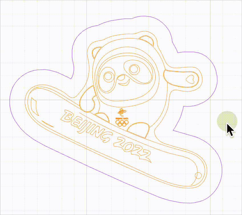
- Precise vector path selection: By default, this function is disabled.
When this function is disabled, you can select a vector path by clicking on the selection box of it. The selections boxes of multiple vector paths, however, may overlap, causing difficulty in selecting the target vector path.
As shown in the following figure, it is difficult to select the purple line because it is located within the selection box of another line.
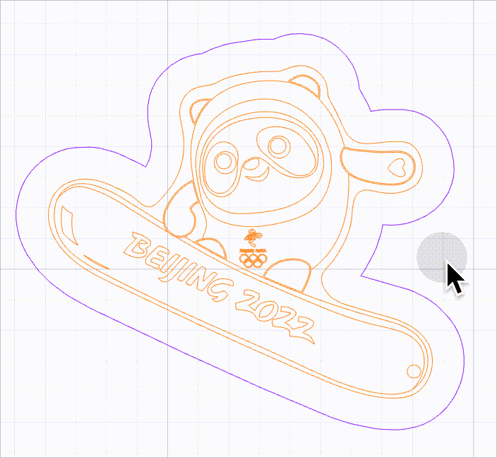
When this function is enabled, no selection box is provided for vector paths. You need to move the mouse pointer close to a line to select it. In this way, you can select a vector path without selection box interfering.
As shown in the following figure, you can select a line by moving the mouse pointer close to it and then clicking.
- Display vector fill: sets whether to display the fill of a vector when its processing types is set to Engrave.
- Hot keys: You can click View to view all the hot keys supported by XCS
- Vector quality: sets the quality of vector paths, including the following options:
- Optimal (ideal for patterns larger than 20 inches and allows for an average speed)
- High (good for patterns of 10 to 20 inches and allows for a moderately faster speed)
- Medium (good for patterns smaller than 10 inches and allows for a fast speed)
The higher the quality, the lower the speed. If you need to edit complicated vector paths, which may cause software lag, empty screen, or crashes, you can set the quality to Medium to improve the performance of XCS. You don't have to worry much about the processing results. In most of the cases, the differences in processing results between the Medium and High quality are not observable. The processing precision is observably reduced only when you scale a small vector path to a very large one, for example, scale a 2-inch pattern to a 20-inch one.
File settings

- Imported image too large for the canvas: sets how to process an imported image that is too large for the canvas, including the following options:
- Ask me every time: XCS asks you every time when you import an image that is too large for the canvas.
- Auto-scale it: XCS automatically scales an image that is too large for the canvas when you import it.
- Keep its size: XCS displays an image that is too large for the canvas in the original size when you import it.
- Precise DXF file parsing: sets whether to parse DXF files with new algorithms. The new algorithms ensure better parsing results without line missing or deformation and therefore use more PC memory. It is disabled by default. You are advised not to enable this function when your DXF files are properly parsed on XCS.
- DXF auto-close tolerance (mm): automatically closes paths, imported from a DXF file, that include split points.
- Log Level: Select the type of log you want to view.
- error: View the error log.
- warn: View the warning log.
- info: View the info log.
- debug: View the debug log.
- Data use agreement: Enable it indicates that your data can be used in algorithm model training.
- Custom parameter settings: allows you to export the processing parameter settings you've saved before or import parameter settings into XCS from a local drive.
Developer mode

You can enter the developer mode to update the firmware of a machine forcibly. Currently, the function is available only for xTool D1, D1 Pro, D1 Pro 2.0, and S1.
About XCS

You can find information about your XCS version, check for updates, and read the privacy policy and terms of service.
Object editing
Using the left side bar, you can add an image, text, shape, vector path, image generated by AImake, array, and duplicate object to a canvas. After adding objects, you can edit them by using the upper panel.
General editing
The general object editing functions are available for all types of objects.

Arrange the stacking order

- Bring to front: moves the selected object, group, or layer to the top of the stacking order
- Send backward: moves the selected object, group, or layer backward one position in the stacking order
- Bring forward: moves the selected object, group, or layer forward one position in the stacking order
- Send to back: moves the selected object, group, or layer to the bottom of the stacking order
Align objects

- Align left: aligns the left edges of the selected objects
- Horizontal align center: aligns the horizontal centers of the selected objects
- Align right: aligns the right edges of the selected objects
- Align top: aligns the tops of the selected objects
- Vertical align center: aligns the vertical centers of the selected objects
- Align bottom: aligns the bottoms of the selected objects
- Align center: aligns the centers of the selected objects
Distribute objects

Distribute horizontally: spaces the selected objects evenly between the leftmost and rightmost edges of the objects in the selection area in the horizontal direction.
Distribute vertically: spaces the selected objects evenly between the leftmost and rightmost edges of the objects in the selection area in the vertical direction.
Reflect an object
You can reflect an object as required.

Reflect horizontally: reflects the selected object using the horizontal center line as the axis.

Reflect vertically: reflects the selected object using the vertical center line as the axis.

Set the position of an object
You can set the position of an object precisely by entering the x and y coordinates of its upper-left edge.
The position (0, 0) is in the upper-left corner of the canvas.


Set the size of an object
You can set the size of an object by entering its width and height. The aspect ratio is locked when you insert or import an object into the canvas. You can click the Lock aspect ratio icon to unlock the ratio.

Rotate an object
You can rotate an object by entering an angle. A positive value indicates rotating clockwise, and a negative one indicates rotating counterclockwise.

Set the corner radius
You can modify a rectangle to a rounded one by entering a corner radius.

Create an outline of an object
You can create an outline for a bitmap, vector path, or text. In addition, you can add an inner outline for a bitmap with a transparent background.

Group and ungroup objects
You can group two or more objects or ungroup them.

Bitmap image editing
Besides the general editing functions, there are design functions available only for bitmap images. You can select an image to activate these functions.

Magic wand
You can select Magic wand to delete an area from the image. The parameter Fuzziness works with the magic wand, indicating the range of pixel colors you delete at a time. The larger the value, the wider the color range, that is, the colors of the pixels to be deleted can be quite different; the smaller the value, the narrower the color range, that is, the colors of the pixels to be deleted are very similar.

Eraser
You can select Eraser to erase a part from the image. The parameter Size works with the erase, including the size of the eraser. The larger the value, the larger the area you erase at a click.

Trace image
You can convert a bitmap image into a vector by using the Trace image function.

- Auto-trace: generates vector outlines along the edges of color blocks within a bitmap. Applicable to multi-color bitmaps with large color blocks.

- Center tracing: generates vector outlines along the centerline of color blocks within a bitmap. Applicable to single-color bitmaps and line drawings.

- Fuzziness threshold: indicates the range of pixel colors for generating vector paths. The larger the value, the wider the color range, that is, the colors of the pixels used to generate the vector paths can be quite different. The smaller the value, the narrower the color range, that is, the colors of the pixels used to generate the vector paths are very similar. Setting range: 0–255
- Denoising: removes the noise of the image. Pixels with a color value lower than the one you set will not be used to generate vector paths. Setting range: 0–100
- Smoothness: sets the smoothness of the vector paths to be generated. The larger the value, the smoother the transition between neighboring pixels. Setting range: 0–1
If you are converting an image with many details, you can enable the Layering by color function. When it is enabled, the vector paths generated are layered by color, and then you can ungroup them and edit each layer.
Add a filter
You can add a filter for your image. The following options are provided: original, grid, sketch, comic 1, comic 2, embossment, black-and-white, and halftone. For embossment, you can set the strength; for halftone, you can set the maximum radius.

Set sharpness
With other settings unchanged, sharpness is related to the clarity of details in an image. The larger value you set, the details are clearer.

Set saturation
With other settings unchanged, saturation is related to the color vibrancy of an image. The larger the value you set, the more vibrant the colors are.

Set brightness
With other settings unchanged, brightness is related to the lightness of an image. The larger the value you set, the brighter the image is.

Set contrast
With other settings unchanged, contrast adjusts the difference between the darkest and lightest colors.The larger the value you set, the greater the difference in color or grayscale in the image.

Set grayscale
The grayscale is related to the contrast of light and shade. Slide the block on the left to the right to enhance the shade. Slide the block on the right to the left to enhance the light.

Invert the color
You can invert the colors of a bitmap image. This function can be useful for the processing of some dark materials, such as engraving bitmap images on transparent or translucent acrylic, black slates, ruber, and mirrors. The engraving results can be improved by using this function.
XCS supports color inverting of black-and-white, grayscale, and color bitmap images, as described in the following:
- Black-and-white images: White pixels are inverted into black ones, and black ones are inverted into white ones.

- Grayscale images: Light pixels are inverted into dark ones, and dark ones are inverted into light ones.

- Color images: A color image is converted into a grayscale image first, and then light pixels are inverted into dark ones, and dark ones are inverted into light ones.

Note: For an image with a transparent or translucent background, the background is not inverted, and only the colors of the pixels in the image are inverted.
Crop
In the Crop image dialog box, you can keep an area and discard those not selected.
Night crop ratios are provided, including random ratio, original ratio, 1:1, 3:2, 4:3, 3:4, 2:3, 16:9, 9:16. You can also set the crop size and click the Lock aspect ratio icon to lock or unlock the ratio.

Create a clipping mask
You can shape a bitmap image with a vector path by making a clipping mask.
(1) Select the bitmap image and vector path.
(2) Click Create mask.
(3) Move the image to the mask.
(4) Click Done.

Text editing
Besides the general editing functions, there are design functions available only for texts. You can enter and select a text to activate these functions.

Typeface
You can select a typeface from the xTool selected or system typefaces.

Attribute
You can set the style or weight of a text.

Leading
You can set the amount of space between lines of text.

Rotate
You can rotate the text after you move the mouse pointer close to the Rotate icon and the pointer changes to a double-arrow curve.

Size
You can set the size of a text by entering a value. The following is a reference.

Curve
You can curve the text by dragging the control on the right.
Weld
This function is used to unite the character strings that overlap one another partially in a text.

Align
You can align the left edge of a text with the left margin, the right edge with the right margin, or center a text.

Spacing
You can set the amount of space between letters.

Vector editing
Besides the general editing functions, there are design functions available only for vectors. You can draw or insert and select a vector to activate these functions.

Set node position
You can set the position of a node precisely by entering the x and y coordinates. The unit can be set in Settings.
The position (0, 0) is in the upper-left corner of the canvas.


Align
You can select a node to align it with the canvas, or select two or more nodes to align them.
- Align a node with the canvas.
For example:

- Select two or more nodes to align them.

Set node type
You can select one or more nodes and set their node types.
Sharp corner

Perfect symmetry

Total asymmetry

Angled symmetry

After editing the nodes, click Done.

Simplify nodes
For complex vectors, you can click Simplify to reduce the number of nodes.
(1) Select the target vector pattern.
(2) Click Edit.
(3) Click Simplify. In the Simplify vector dialog box, you can adopt the auto-simplification result or use the Simplification slider to reduce the number of nodes.
(4) Click Done.

Split path
You can split a path between nodes.
(1) Select the target vector path.
(2) Click Edit.
(3) Click Scissors on the upper panel.
(4) Move the cursor onto the path segment you want to split and click the target path segment. You can also click Select to go back to the previous step.
(5) Click Done in the upper right corner.

Set compound
Edit compound
You can click Edit compound to set the position, align, and reflect one or more vectors.


Release or make compound vectors
You can release or make a compound vector.

Set pathfinder
By selecting two or more vectors, you can set pathfinder.
Unite

Subtract

Unite at overlap

Subtract at overlap

