Issue description
- There is a significant discrepancy between the device's actual processing position and the pattern position in the software.
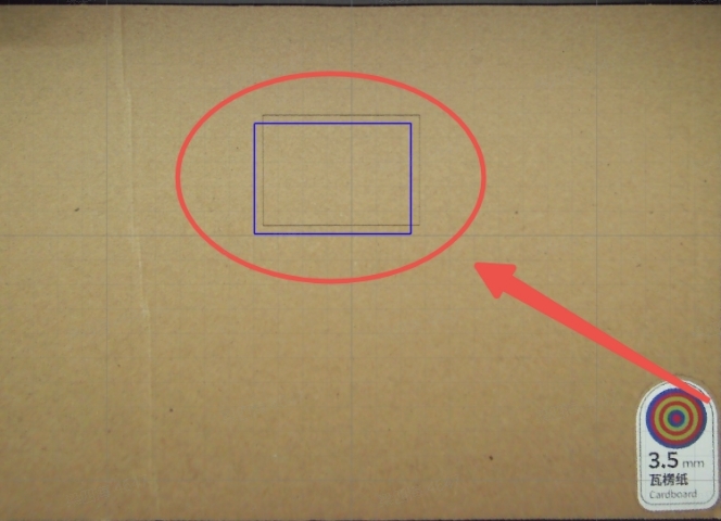
- There is a significant discrepancy between the size of the items in the photos and their actual dimensions.
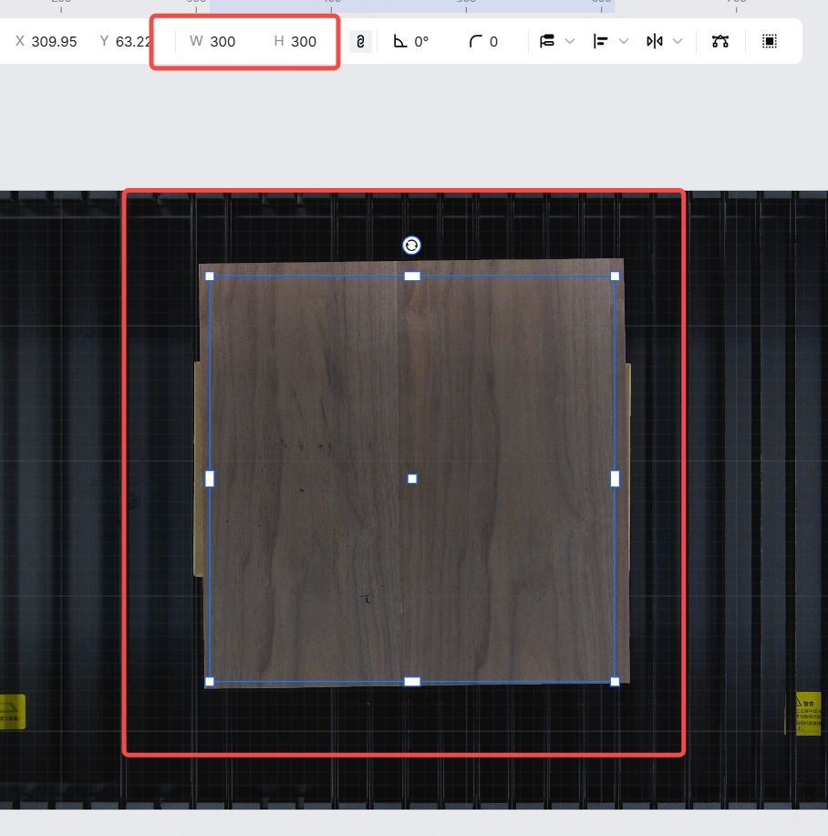
Possible causes
- Poor material flatness
- Improper slat installation / uneven baseplate
- Inaccurate measurement
- Material movement
- Camera calibration issue
Prerequisite
This solution applies to both distant-view camera and close-view camera.
- Camera positioning error
The deviation between the position of the processed object in the image captured by the software and the actual processing position of its pattern. This error is directly related to factors such as material flatness, ranging accuracy, and assembly tolerances, so it cannot be completely avoided. In addition, the closer the processing position is to the edge, or the more the height of the processing position deviates from the top surface height of the slats, the greater the error will be.
Please first confirm whether the camera positioning error is normal before proceeding with any handling.
- Positioning accuracy description
When using camera positioning, if processing 3 mm material at the center of the processing area, the positioning accuracy of the distant-view camera and the close-view camera is as follows:
- The theoretical positioning accuracy of the distant-view camera is 1 mm.
- The theoretical positioning accuracy of the close-view camera is 0.5 mm.
If the camera positioning accuracy deviation of your device under these conditions is significantly greater than the theoretical value, this indicates a problem with the camera positioning. You can refer to this article for troubleshooting.
- How to measure camera positioning error
After processing is complete, please refresh the camera.
You can use the built-in measurement feature to measure the distance between the line segment position in the software and the actual processed position. This distance is the error caused by camera positioning.
- If the positioning accuracy is within a reasonable range, no action is required.
- If the camera positioning accuracy is normal but still cannot meet your accuracy requirements, you can first use material to perform a processing test, determine the final processing position and height, and then proceed with formal processing.
Troubleshooting procedures
1. Check the flatness of the material
Ensure that the material is flat, with no warping or distortion. If the material is not flat, positioning errors will be greater in the distorted areas; please replace it with a flat piece of material before continuing processing.
2. Check the slats installation
Make sure the slats are properly installed and keep level.
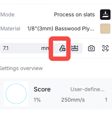
3. Check the distance measurement status
The zoom ratio of the camera preview image changes with the material height. Please check whether the distance was remeasured before processing.
If the actual material height does not match the measured distance, the material's size in the image will not match its actual size, which will ultimately affect the accuracy of camera positioning.
4. Check the material placement
Check whether the material is moved by the airflow from the air nozzle during processing. If so, secure the material with material clamps or masking tape before continuing processing.
5. Check the camera modules
Make sure the camera module is securely fastened. If it is loose, refer to the guide to reattach it.
- For the close-view camera: Replace the Close-View Camera and Its Fill Light Board for xTool P2 - xTool Support Center
- For the distant-view camera: Replace the Distant-View Camera of xTool P2 - xTool Support Center
6. Check the distance measurement position
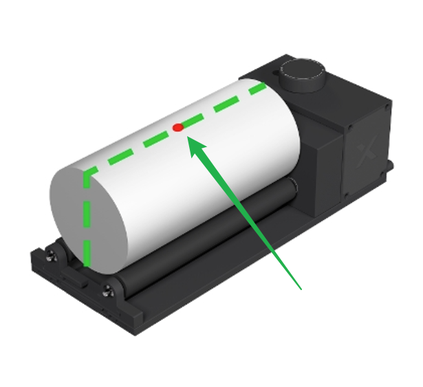
The camera preview image will be scaled based on the measured material height value. If the material is not a flat plane, please ensure that the measurement point is located on the material's processing plane.
For example, when processing cylindrical material with a rotary attachment, ensure that the measurement point is located at the highest point of the cylindrical material.
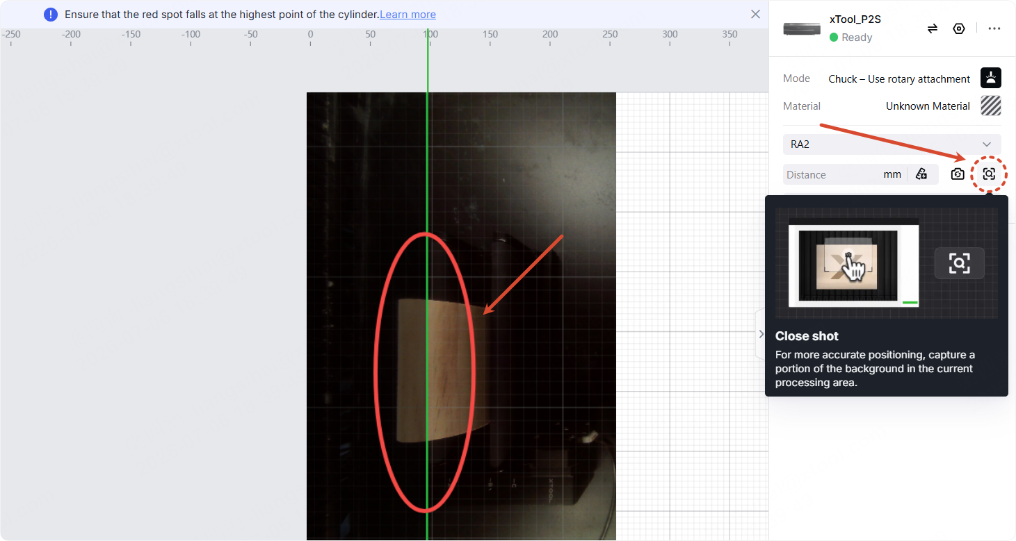
7. Use the "Close shot" function
When processing cylindrical or spherical materials (especially when using a rotary attachment), because the machined surface is not flat, after the software scales the material, the material in the photo may show obvious distortion and stretching. In this case, distant-view positioning may not accurately locate the highest point of the material.
It is recommended that after completing the distance measurement, use Close Shot for positioning.
8. Perform the camera calibration
If the discrepancy persists after the above checks, it indicates that camera calibration is required.
For the close-view camera: Calibrate Close-view Camera for P2/P2S
For the distant-view camera: Calibrate Distant-view Camera for P2/P2S
If none of the above works
If you have any questions, collect the troubleshooting steps you have taken and the product SN, shoot a video of the issue, and contact us for further assistance at: support@xtool.com.