When engraving graphics such as logos or photos on cylindrical or tapered objects, image distortion may occur due to the difference between the chord length and the arc length of the curved surface. To compensate for this effect, we have added an image correction feature to xTool Rotary Attachment 3 (RA3).
Below are two examples showing successful results after applying image correction.
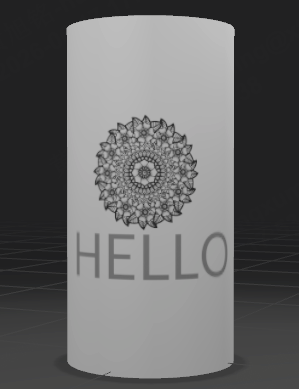
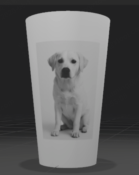
Follow the image correction steps below to achieve the best engraving results.
Step 1
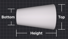
- For tapered objects, to obtain the data required for accurate image correction, we need to measure several dimensions, including the diameter or circumference of the top base (the side closer to RA3's jaw chuck), the diameter or circumference of the bottom base (the side farther from RA3's jaw chuck), and the height (the vertical distance between its top and bottom bases). In addition, we need to know the exact position of the image on the tapered surface, such as the distance between the image center and either the top or bottom base measured along the side of the object.
- For cylindrical objects, this process is much simpler. We only need to measure the cylinder's diameter or circumference.
Step 2
For P series laser devices (including P2, P2S, and P3):
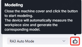
In RA3 Auto Mode, all the information required for image correction can be obtained accurately through Modeling. However, if you are familiar with the process and already have the necessary parameters, RA3 Manual Mode may be a faster option.
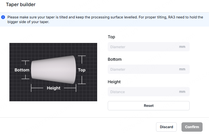
In RA3 Manual Mode, you need to enter the top diameter, bottom diameter, and height in the Taper builder to create a taper model. In addition, you must enter the diameter or circumference at the engraving position. We recommend using RA3's jaws to grip the wider section of the workpiece. In RA3 Manual Mode, use the support module and the mini level to raise the tapered workpiece until the surface to be engraved is level.
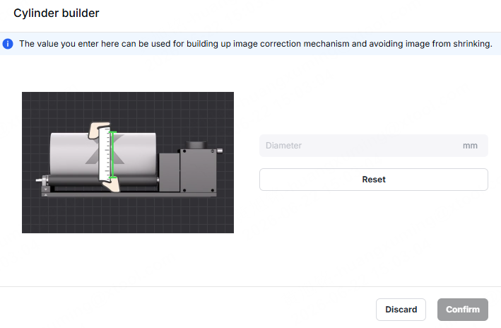
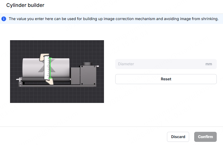
In RA3 Manual Mode, when the processing mode Roller – Use rotary attachment is selected, there is a Cylinder builder. Simply enter the diameter of the cylindrical workpiece to create a cylinder model.
For F series laser devices (including F2, F2 Ultra, and F2 Ultra UV):
F series laser devices support image correction for cylindrical objects only. In RA3 Manual Mode, you need to enter the diameter or circumference of the cylindrical workpiece. In RA3 Manual Mode, when the processing mode Roller – Use rotary attachment is selected, there is a Cylinder builder. Simply enter the diameter of the cylindrical workpiece to create a cylinder model.
Step 3
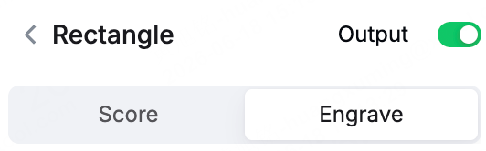
After creating the cylinder or taper model, select the image you want to correct and make sure its processing mode is set to Score or Engrave.

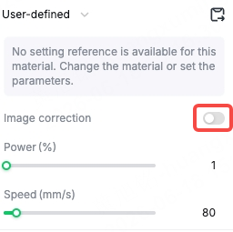
You can find the Image correction toggle in the processing settings. Turn it on to apply image correction.
 →
→
Step 4
After completing the steps above, click Preview to check the image correction result. If the correction result is not as expected, the following may be the cause:
(1) Incorrect parameters were input. Check the cylinder or taper shape shown in the Preview. If it differs significantly from the actual shape of the workpiece you are using, the input parameters may be incorrect.
(2) The image is not suitable for correction. Some images are not suitable for image correction, such as large-format designs that cover more than half of the cylinder or taper surface, or full-wrap designs.
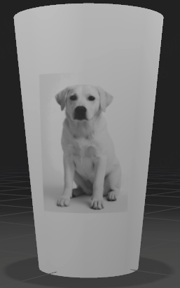
If the preview result looks correct, you can proceed with processing.
Tips
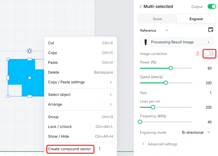
Tip 1: If the graphic you want to engrave consists of multiple vector objects, you can combine them into a single compound vector before enabling Image correction.
P2/P2S's related screenshot:
P3's related screenshot:
F2/F2 Ultra's related screenshot:
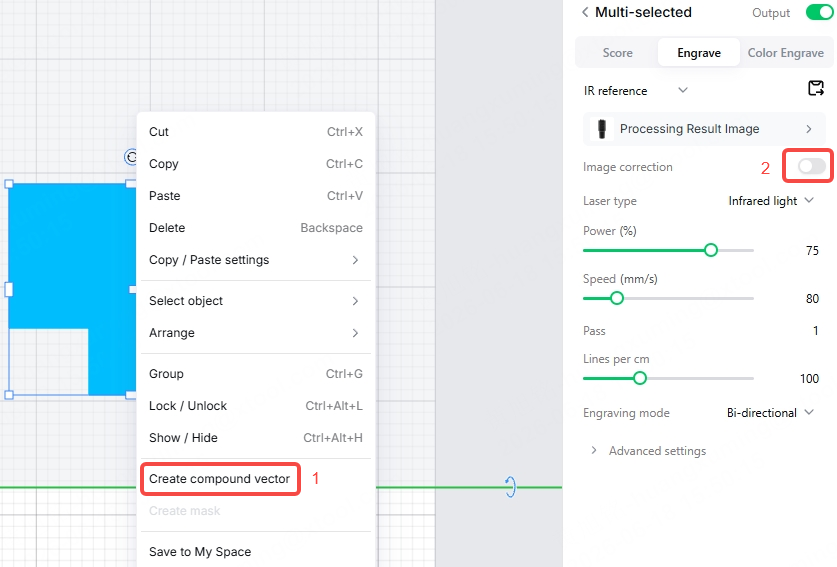
F2 Ultra UV's related screenshot:
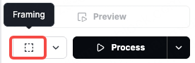
Tip 2: To ensure precise positioning, after applying image correction, click Framing in the lower-right corner of the software interface to preview the engraving position.

Related links
Use Rotary Attachment 3 (RA3) with xTool P3
Use Rotary Attachment 3 (RA3) with xTool P2/P2S
Use Rotary Attachment 3 (RA3) with xTool F2 Ultra UV