A material grid test helps you quickly find suitable processing parameters for your material. After the test is complete, you will see a test array made up of multiple small grids. Each grid represents a different parameter combination, such as different power and speed settings.
This article explains how to read the test results and choose suitable parameters for engraving, marking, or cutting.
What Is a Material Grid Test?
A material grid test is a parameter testing method. Studio processes multiple test grids on the same piece of material, and each grid uses a different set of parameters.
In most cases:
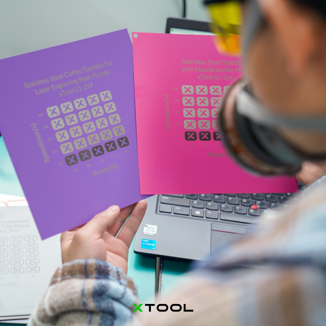
- The horizontal axis represents one parameter, such as Power.
- The vertical axis represents another parameter, such as Speed.
- Each grid represents one specific parameter combination.
- After processing is complete, you can observe the effect of each grid and choose the most suitable parameter set.
Simply put:
Each grid = one combination of power and speed.
Your goal is to find the grid whose result best matches your expected processing effect.
Step 1: Understand the Horizontal and Vertical Axes
The test array usually shows two parameter directions.
A common setup is:
- Horizontal axis: Power, usually shown as a percentage.
- Vertical axis: Speed, usually shown in mm/s.
For example, if a grid is located at:
- Power: 60%
- Speed: 100 mm/s
Then the processing parameters for that grid are:
Power 60%, Speed 100 mm/s
When reading the grid, you can identify each grid’s parameters by checking its column and row.
Step 2: Understand How Parameter Changes Affect the Result
In general:
The higher the power, the stronger the processing energy.
The slower the speed, the more energy the material receives.
As a result, different areas of the test array usually show the following patterns:
Parameter Combination | Common Result |
Low power + high speed | Too light, unclear, or may not cut through |
High power + low speed | Too deep, darkened, burned, melted edges, or deformation |
Medium power + medium speed | More likely to produce a clear and stable result |
When choosing parameters, you do not necessarily need to choose the darkest grid.
What matters more is choosing a grid with a clear result, clean edges, and no obvious overburning.
Step 3: Choose the Right Result Based on Your Processing Goal
Different processing goals have different standards for what counts as a good result.
If You Want to Engrave or Mark
Choose a grid that meets the following conditions:
- The pattern is clear.
- The contrast is sufficient.
- The edges are clean.
- There is no obvious burning, yellowing, or smoke staining.
- Small details are not blurred.
- The material surface is not obviously deformed.
Recommended choice:
Among the clearly visible grids, prioritize parameters with lower power, higher speed, and cleaner edges.
This usually helps reduce burning while improving processing efficiency.
If You Want to Cut
Choose a grid that meets the following conditions:
- The material is fully cut through.
- The edges are not severely darkened.
- The burn marks on the back side are relatively light.
- There is no obvious melting, residue, or deformation.
- The cut piece can be removed smoothly.
Recommended choice:
First find the area that can just cut through the material, then choose a parameter set with slightly more stability.
Do not directly choose the highest power and lowest speed grid. Although these parameters are more likely to cut through the material, they are also more likely to cause burned edges, material deformation, or a wider cut line.
If You Want to Remove Coating or Process a Metal Surface
Choose a grid that meets the following conditions:
- The coating is removed cleanly.
- The color is even.
- The edges do not spread noticeably.
- There is no yellowing, graying, or overburning.
- Small patterns and text remain clear.
Recommended choice:
Choose a grid that removes the coating completely without blurring the edges.
If the parameters are too light, coating may remain. If the parameters are too strong, the surface may turn yellow, turn gray, or show edge spreading.
If You Want to Process Photos, Filled Graphics, or Bitmaps
Choose a grid that meets the following conditions:
- The light and dark tones look natural.
- The fill is even.
- There are no obvious horizontal or vertical lines.
- Details are well preserved.
- There is no large-area burning or excessive depth.
Recommended choice:
Do not simply choose the darkest grid. Choose the grid with the most natural tonal layers and the clearest details.
For photos or bitmaps, evenness and tonal detail are usually more important than depth.
Step 4: Exclude Unsuitable Grids
Before choosing the best parameters, first exclude grids with the following issues:
- Too light or unclear
- No visible processing mark
- Not cut through
- Obvious burning or carbonization
- Blurred edges
- Melting, warping, or deformation
- Loss of pattern details
- Heavy burn marks on the back side
These grids are usually not suitable as final parameters.
Step 5: Find a “Usable Area” Instead of Looking at Only One Grid
When choosing parameters, it is recommended not to focus on only one grid. Instead, check whether there is a continuous area with good results.
If a grid looks good and the grids around it also look acceptable, this means the parameter set has a wider tolerance range and is more stable for processing.
Recommended choice:
Choose parameters from the middle of a continuous good area.
This is more reliable than choosing a grid at the edge of the usable range.
For example:
- One grid looks good.
- The grids to its left, right, above, or below are also acceptable.
- This area is usually relatively stable.
On the other hand, if only one grid looks good while the surrounding grids are too light or too burned, that parameter set may be sensitive and may not be suitable for long-term use.
FAQ
Is the darkest grid always the best parameter?
Not necessarily.
The darkest grid usually means stronger energy, but it may also mean overburning, carbonization, or material damage. The best parameter should be chosen by considering clarity, edge quality, burn level, and the processing goal.
For cutting, should I choose the parameter that just cuts through?
It is recommended to choose a parameter that cuts through with a small safety margin.
If the parameter just cuts through but is not stable, slight changes in material thickness or flatness may cause incomplete cutting. You can slightly increase the power or lower the speed based on the parameter that just cuts through.
What should I do if the engraving is too light?
You can try:
- Increasing the power
- Lowering the speed
- Increasing the number of passes
It is recommended to adjust in small steps to avoid adding too much energy at once and causing burning.
What should I do if the engraving edges are dark or blurry?
You can try:
- Lowering the power
- Increasing the speed
- Reducing the number of passes
- Checking whether the material surface is prone to smoke staining
- Using masking paper or improving smoke extraction if needed
Can I always use the same parameter set for the same material?
Not always.
The material’s color, thickness, surface treatment, moisture content, and batch differences can all affect the processing result. Even for the same type of material, it is recommended to run a small test before formal processing.
Quick Reference
You can use the following rules for quick judgment:
Too light: increase the power or lower the speed.
Too deep: lower power or increase speed.
Burned: lower the power or increase the speed.
Not cut through: increase power or lower the speed.
Blurry edges: lower the power or increase the speed.
Unstable result: choose a grid in the middle of a continuous good area.
Recommended Parameter Selection Process
- Check the horizontal and vertical axes to confirm the parameters for each grid.
- Exclude grids that are too light, not cut through, burned, melted, or deformed.
- Find a continuous area with clear results and clean edges.
- Choose parameters based on your processing goal:
- For efficiency: choose a qualified grid with higher speed.
- For detail: choose the grid with the cleanest edges.
- For cutting through: choose a grid that cuts through with lighter burn marks.
- For stability: choose a grid in the middle of a continuous good area.
- Use the selected parameters to run a small sample test.
- After confirming the result, proceed with formal processing.
Summary
The purpose of a material grid test is to help you find more suitable parameters before formal processing.
When choosing a result, do not only look for the darkest grid. Instead, consider:
- Whether it meets your processing goal
- Whether the result is clear
- Whether the material is cut through
- Whether there is overburning
- Whether the edges are clean
- Whether nearby parameters are also stable
In most cases, a grid in the middle of a continuous good area is more suitable as the final parameter than a single extreme grid.
Services & Help
Learn & Education

Copyright © 2025 xTool All Rights Reserved.