Prerequisites
- xTool Studio software version 1.58 and above supports distance sensor calibration. If your software version is below this, please update it.
- Due to assembly and material dimensional tolerances, minor measurement errors are unavoidable and considered normal. You can click the link to verify whether the measurement accuracy is within normal limits.
- If the measurement accuracy is within the normal range, no further processing is required.
- If the measurement accuracy is out of the normal range, the distance sensor requires calibration.
Applicable scenarios
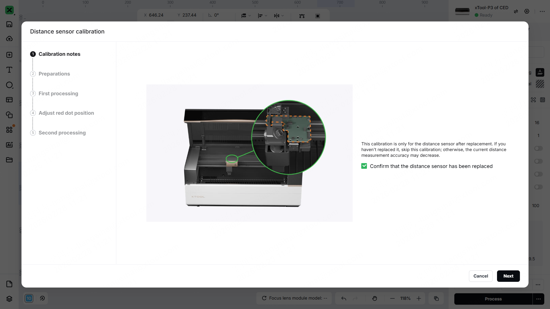
- After the distance sensor replacement
- Failure to autofocus or ranging failure caused by large errors in ranging accuracy
- Ranging failure caused by missing calibration data of the distance sensor
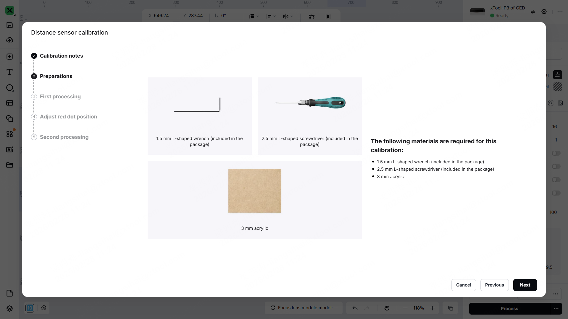
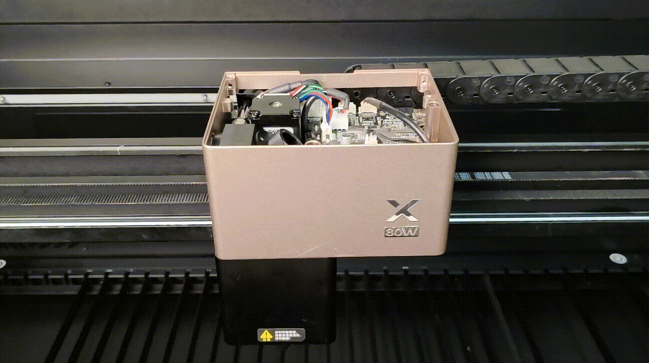
Tools required
- A 3 mm acrylic sheet (with protective film), larger than the size of 150 mm * 150 mm
- A hex key M1.5mm
- A hex key M2.5mm
- A Philips screwdriver
Matters need attention
- Choose a flat 3mm material, such as acrylic board (other flat 3mm materials can also be substituted).
- The laser module will lock during calibration. Do not force it to move, as this may cause misalignment. If the laser module is accidentally moved, restart the device and repeat the procedure.
- The material cannot be moved during calibration. If the material is moved, recalibrate it.
- When adjusting the distance sensor screws, do not allow the screwdriver contact the components on the PCBA.
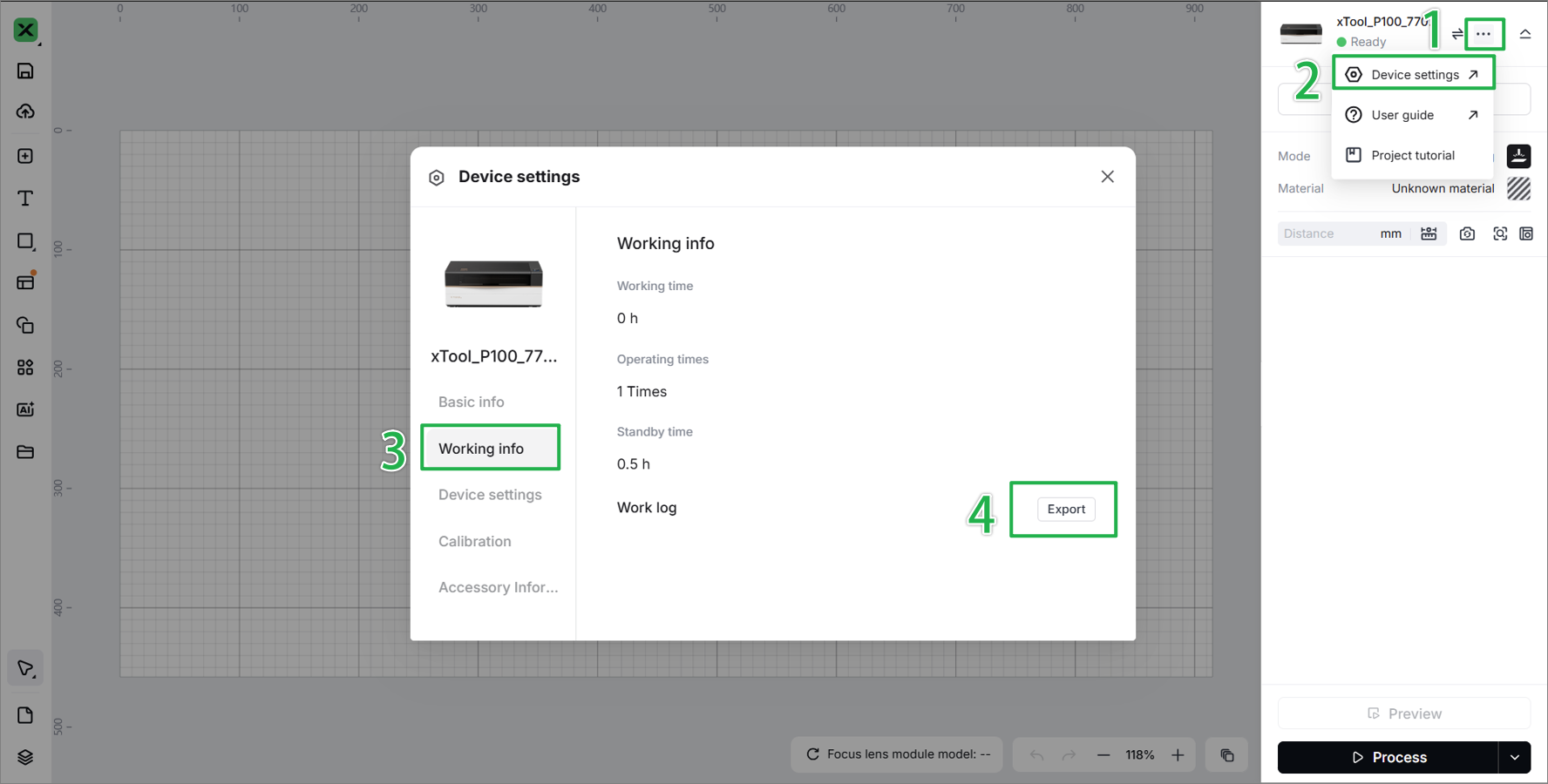
- If the calibration consistently fails, record a calibration video, export a work log, and send it to xTool after-sales service.
Calibration procedures
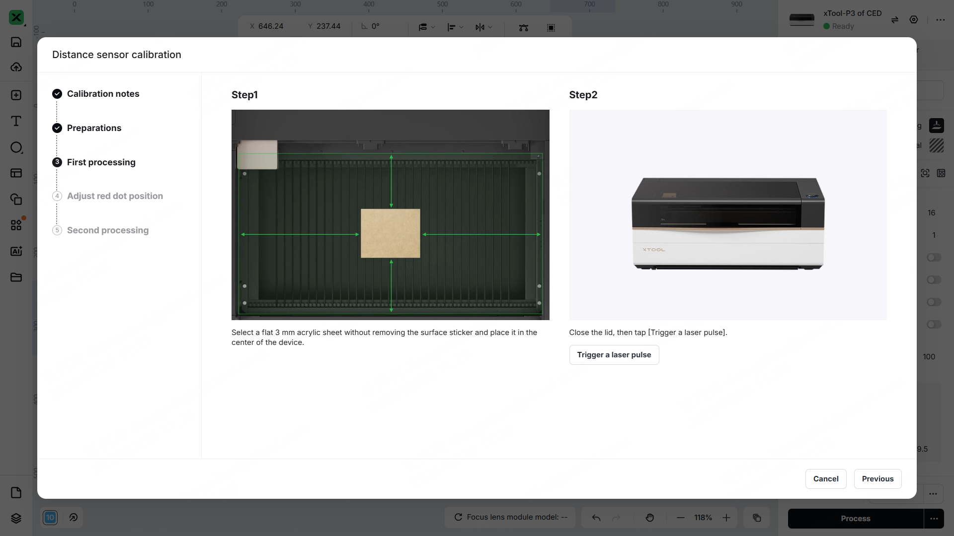
1. Preparations
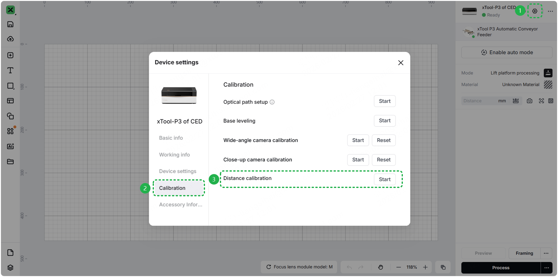
(1) When the device connects to xTool Studio (version 1.58 and above), go to > Calibration.
(2) Press and hold the keyboard keys for 5s to open the hidden calibration entry.
- For Windows:
Ctrl+Shift+C - For macOS:
Command+Shift+C
(3) Follow the instructions in the software to finish the preparations.
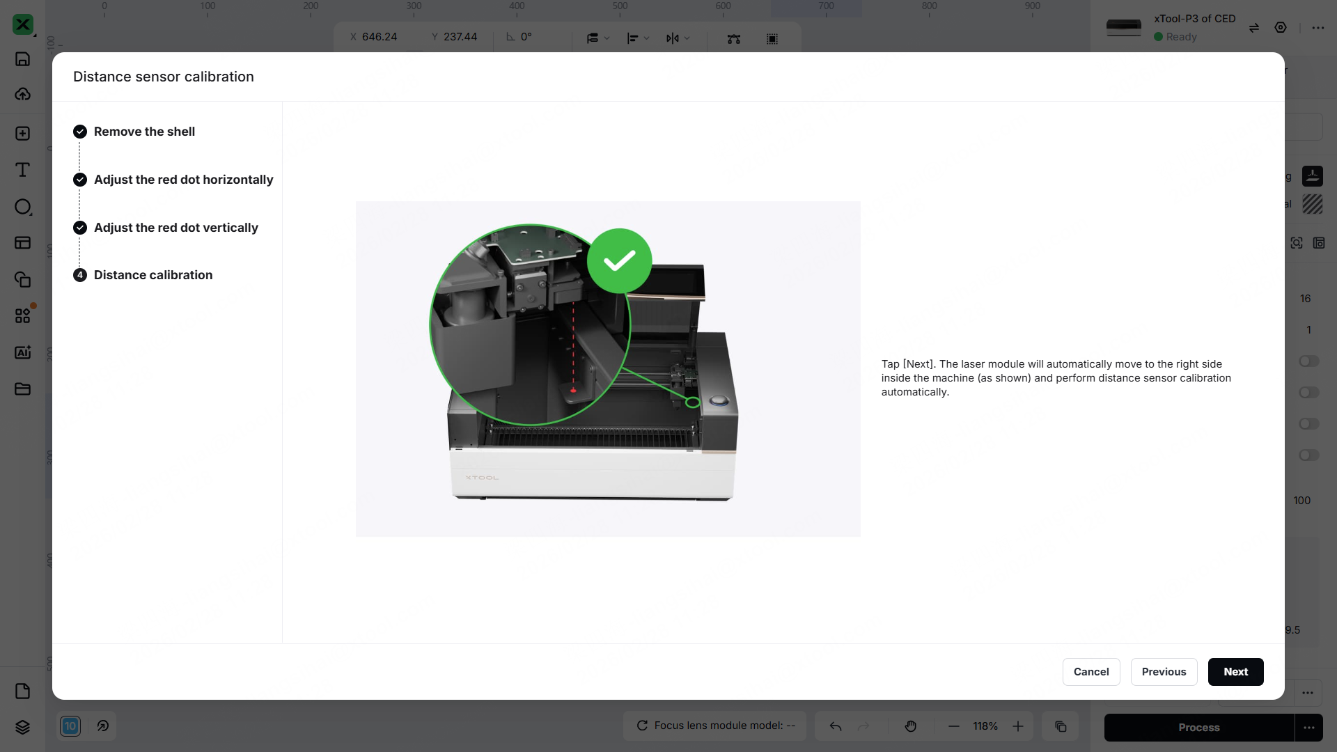
2. Test
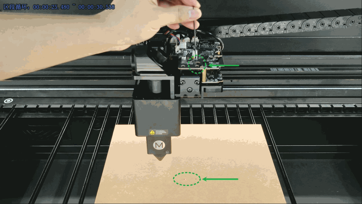
(1) Place the material in the center of the lifting platform. And click Trigger a laser pulse. (If the laser spot mark is not obvious, go back to the previous step to trigger the laser again.)
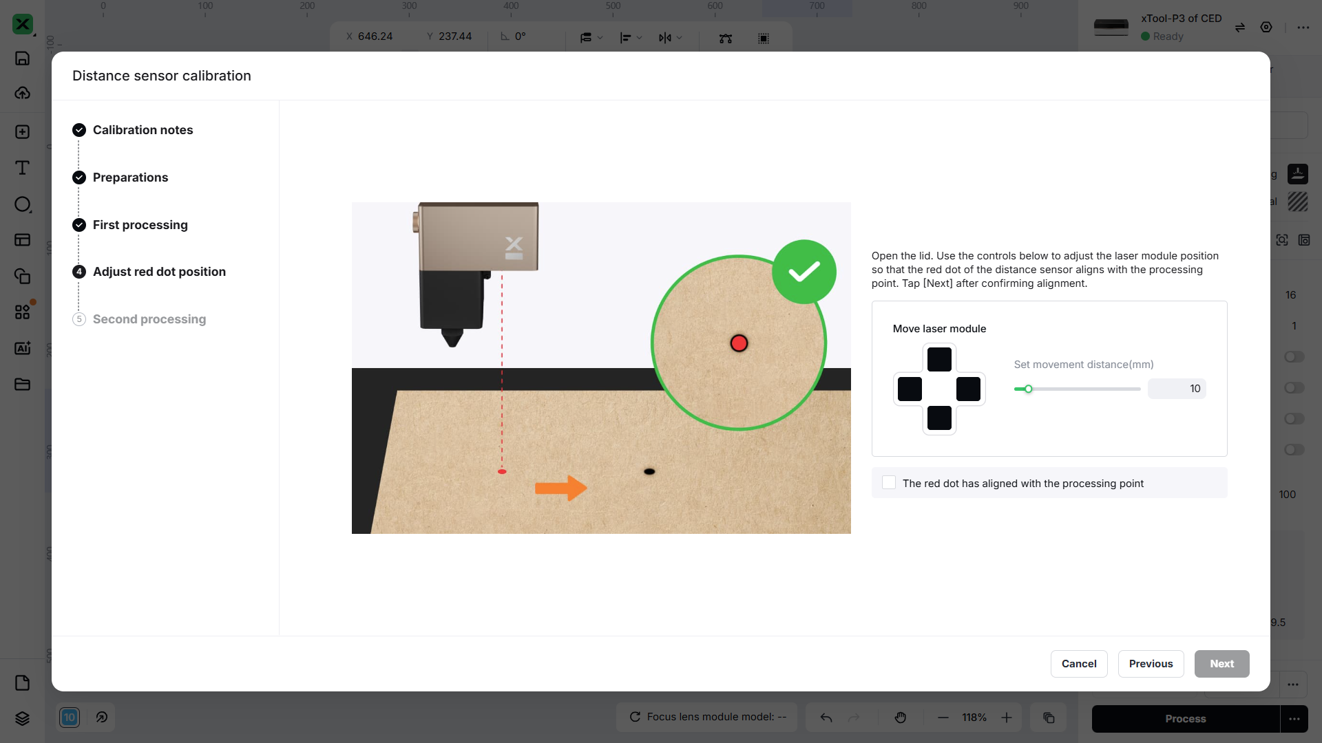
(2) To set the movement distance of the laser module, click the arrow button to make the red spot of the distance sensor and laser spot overlap.
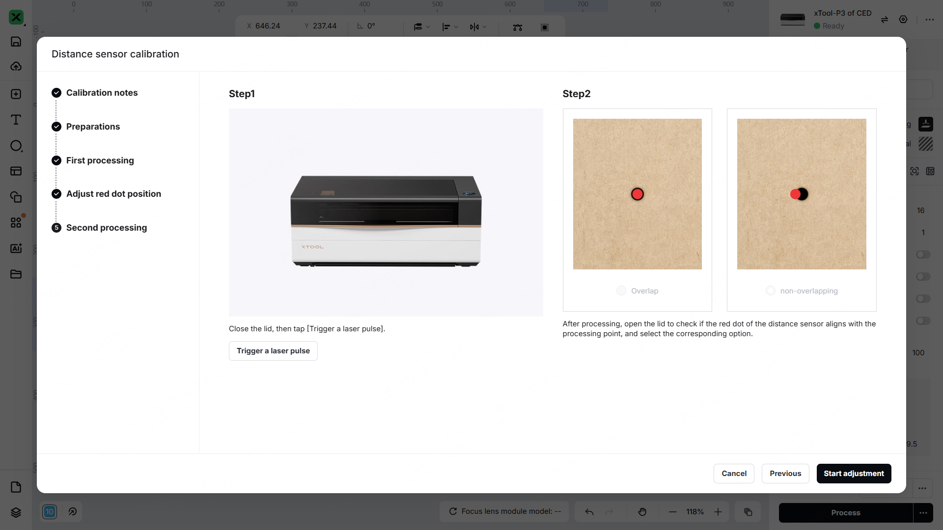
(3) Trigger a laser pulse for a second time. Check whether the red spot overlaps the laser spot.
- If the red spot overlaps the laser spot, select Overlap > Start adjustment to complete the calibration.
- If they are not overlapped, select Non-overlapping. Then follow Step 3 Start calibration to calibrate.
3. Start calibration
(1) Rotate anticlockwise to remove the fixed screws and laser window.
- The red ones are Philip's head screws.
- The green ones are hex screws.
- The blue one is a laser window.
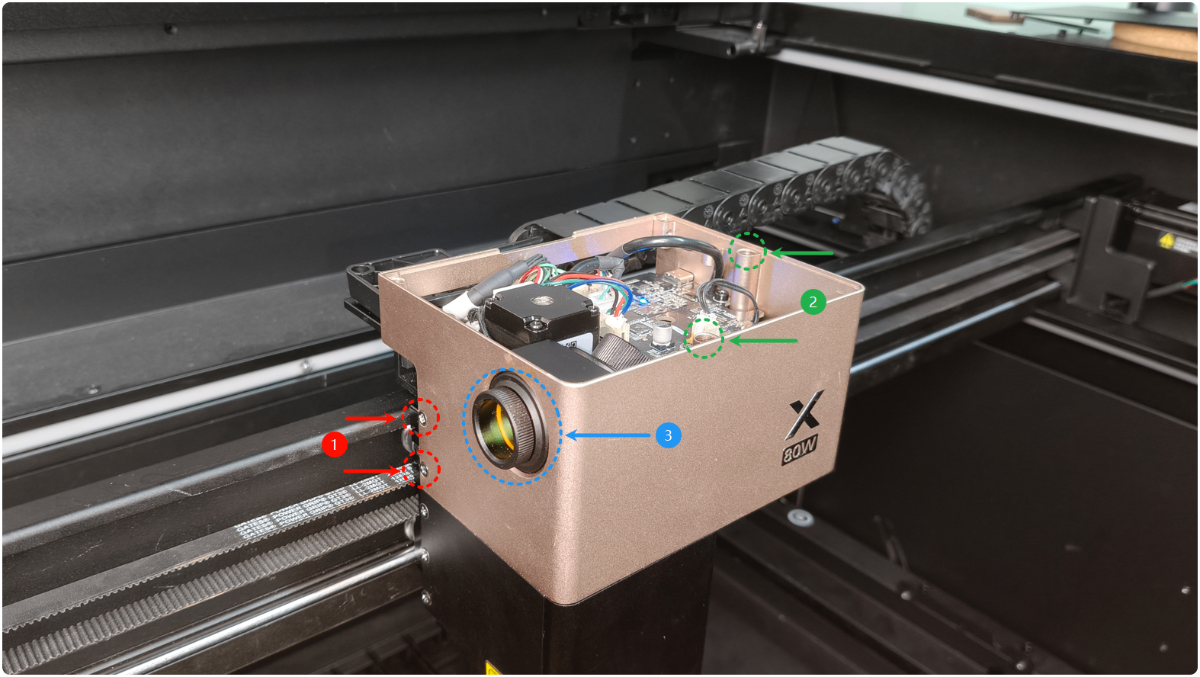
(2) Remove the upper cover of the laser module.
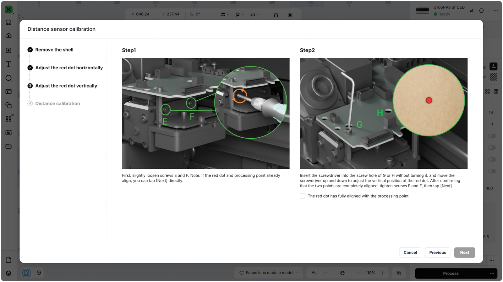
(3) Align the red dot and laser dot vertically:
- Method 1: Refer to the instructions in the software. Loosen screws A and B (no need to remove them). Adjust screws C and D alternately (loosen one while tightening the other) until the red dot and laser spot align vertically. Then tighten screws A, B, C, and D in sequence before proceeding to the next step.
- Method 2: Loosen the four screws ABCD (no need to remove them). Refer to the GIF below to adjust the red dot and laser spot of the distance sensor until they align vertically. Maintain this alignment, then tighten the four screws ABCD in sequence before proceeding to the next step.
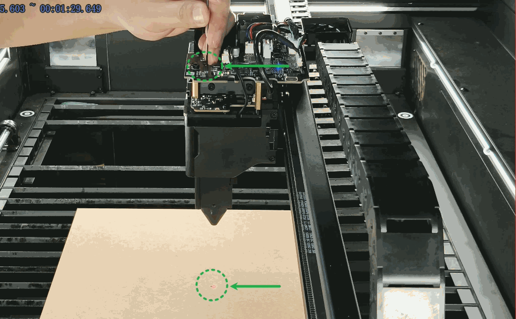
(4) Make the red dot and laser dot overlap:
- Method 1: Refer to the instructions in the software. Loosen screws E and F (no need to remove them). Press screws G and H alternately until the red dot and laser spot overlap. Then tighten screws E, F, G, and H in sequence before proceeding to the next step.
- Method 2: Loosen the four screws EFGH (no need to remove them). Refer to the GIF below to adjust the red dot and laser spot of the distance sensor until they overlap. Maintain this alignment, then tighten the four screws EFGH in sequence before proceeding to the next step.
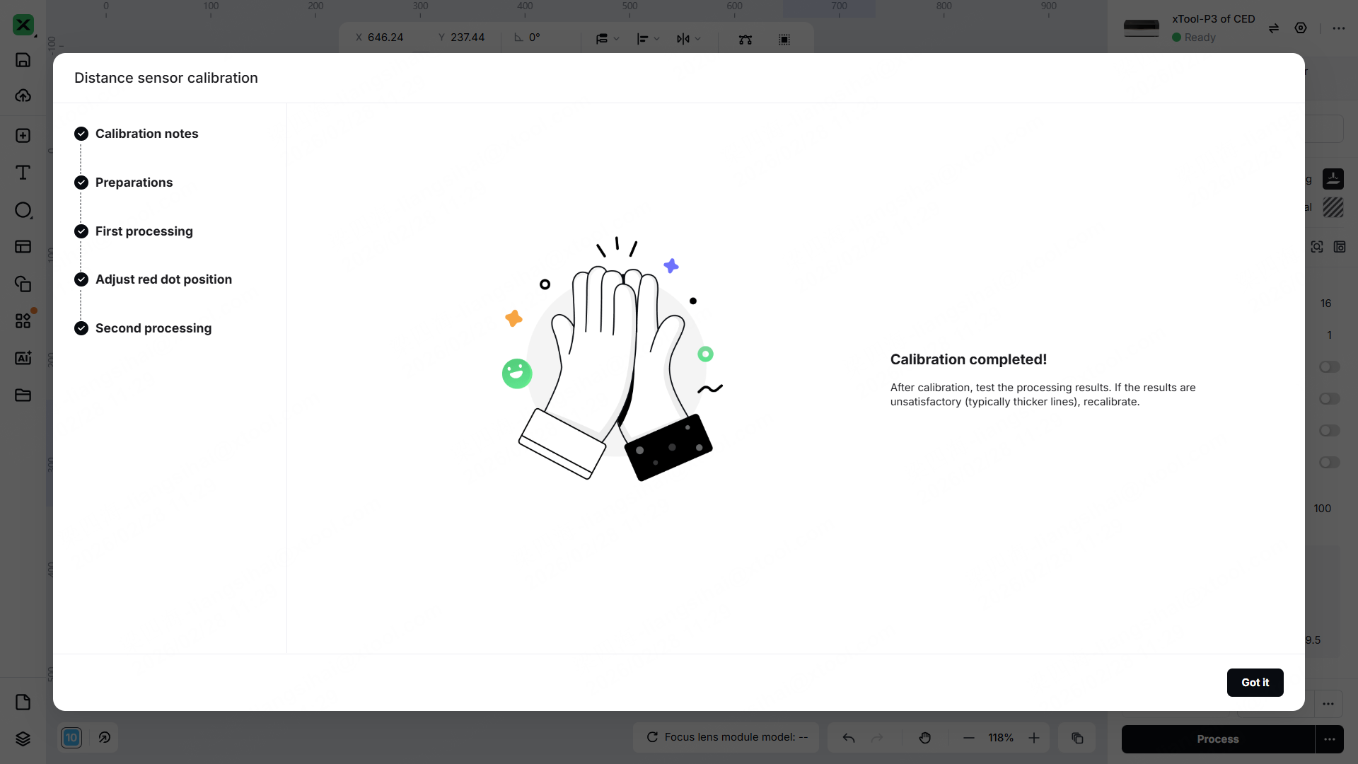
4. Complete the calibration
After calibration is complete, test whether the distance measurement function works properly.
- If functionality returns to normal, reinstall the cover of the laser module.
- If the distance measurement continues working improperly, try recalibrating.
Still experiencing issues?
Should the issue persist after completing the preceding steps, submit a ticket via the "Submit a Ticket" button in the "Help Ticket" section below. The standard response time for xTool Customer Service is one business day.
For a prompt resolution, please include the following details:
- Issue description: A detailed explanation of the observed problem.
- Video evidence: Attach a video demonstrating the issue, where applicable.
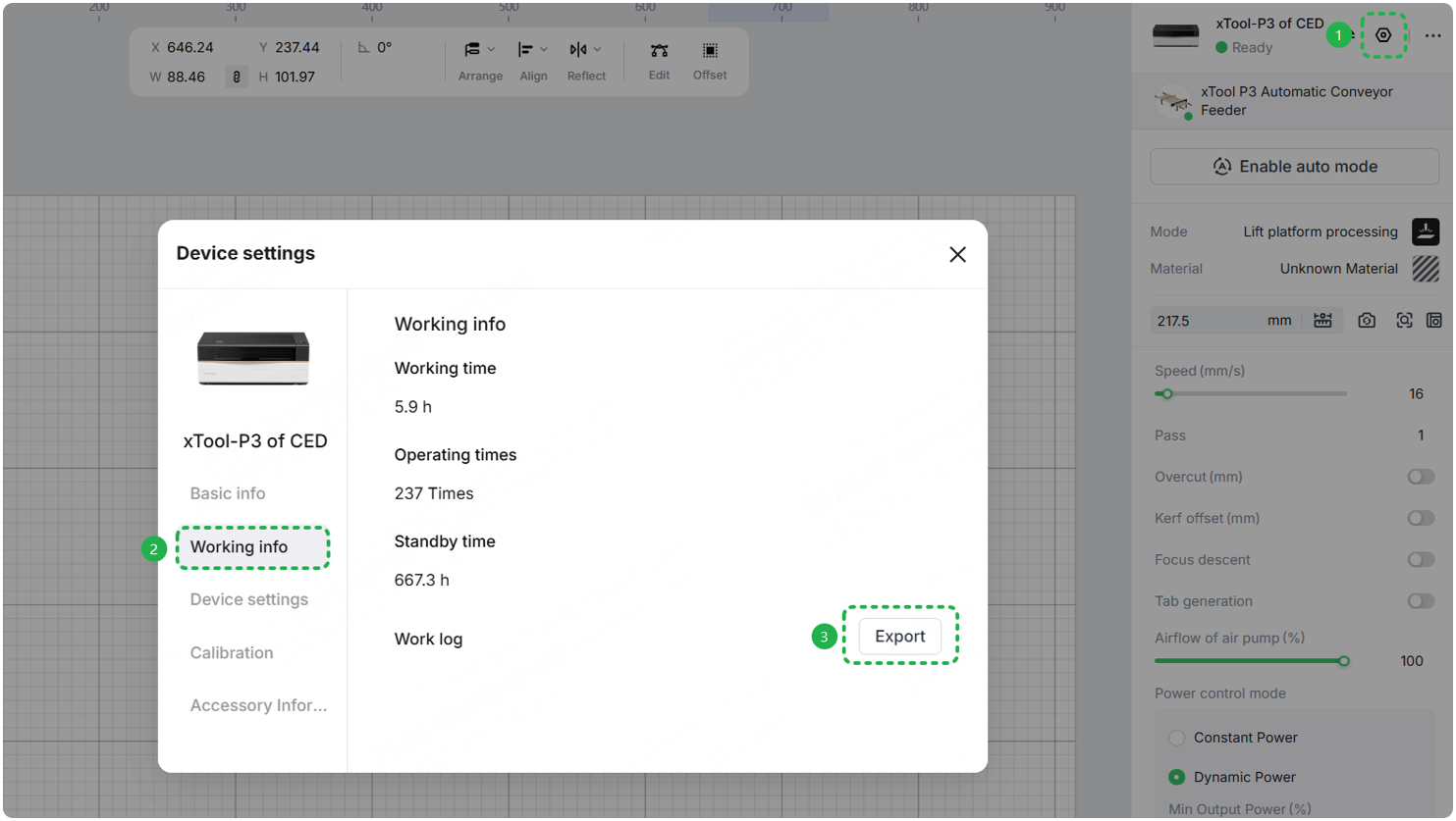
- Device information: Follow the steps to find the SN and export the work log.
- Troubleshooting performed: Any troubleshooting steps you have already attempted, along with their results.
This information is crucial for xTool technical support engineers to provide timely assistance.
Documentation feedback
Help improve this content by providing feedback. If this content did not meet your requirements, select "No" in the "Was this page helpful?" section below. Include specific details about what was unclear or missing in the pop-up suggestion box. Feedback submissions are reviewed by xTool technical writers to enhance future documentation.
