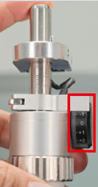
The cutting tip knob has a value range of -10 to +5, allowing you to adjust the focus position within this range. However, when processing certain materials, such as 4 mm #45 carbon steel, the required value may exceed this range. In such cases, turning the knob alone won't suffice. Instead, the U-shaped component and extension tube are necessary for precise adjustment.
This article explains the adjustment method when the value exceeds the cutting tip knob range [-10,5]*.
*[-10,5] means values ranging from -10 to +5, which includes -10 and +5.
![Value exceeding the range [-10,5]](https://storage-us.atomm.com/resource/xtool/xcs-cms/community/activity/9b6d92c8-805f-4f0a-b1d9-9ab919bb4a2e_9904b0ed-9548-4835-9981-edb9eefef032_image.png)
Value exceeding the range [-10,5]
Related items
Figure |
|
|
|
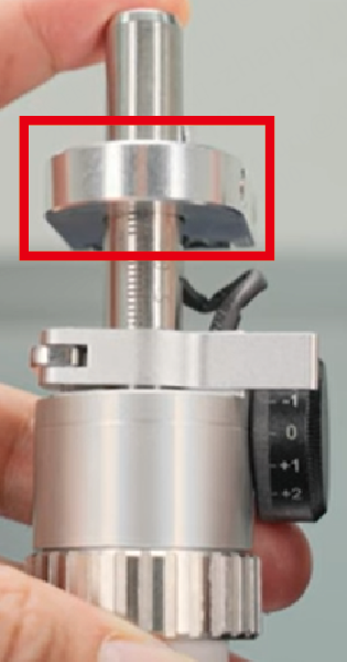
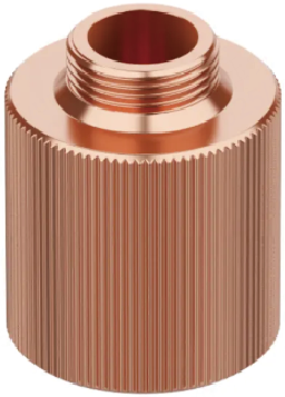
Name | Cutting tip knob | U-shaped component | Extension tube |
Value/Value range | -10 to 5 | -3 to 3 | 20 |
Adjustment steps
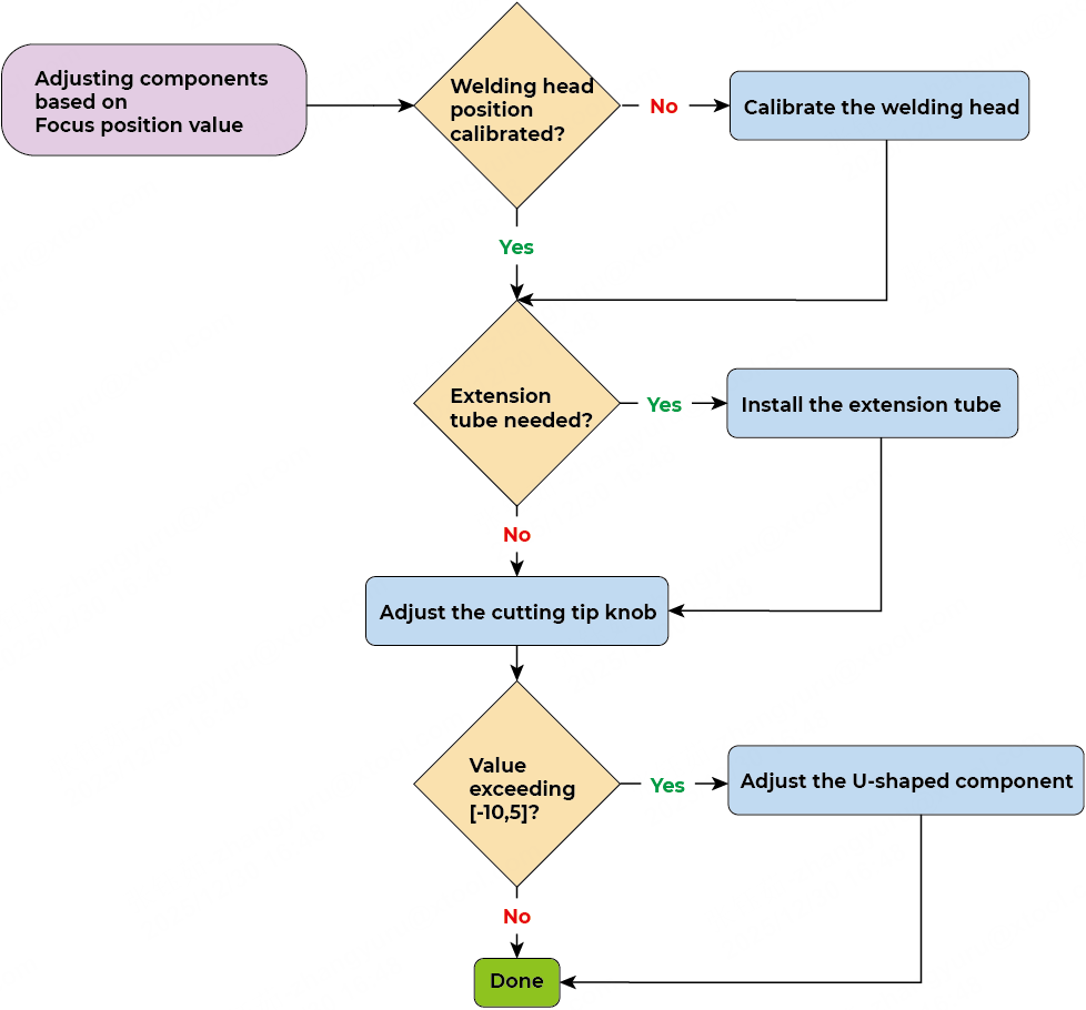
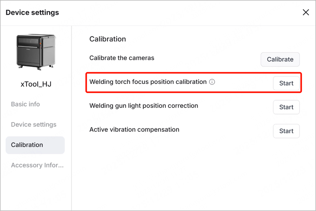
Step 1: Ensure that the welding head has been calibrated
Before processing, you need to complete all the calibration tasks in xTool software, including calibrating the welding head (torch) focus position.
For instruction details, visit xTool MetalFab CNC Cutter - Unboxing and First Use and watch the video from 10:38.
Step 2: Check if the extension tube is needed
- After choosing your processing material in xTool software, the parameters will be automatically set. Check if the recommended nozzle is required to use with an extension tube.
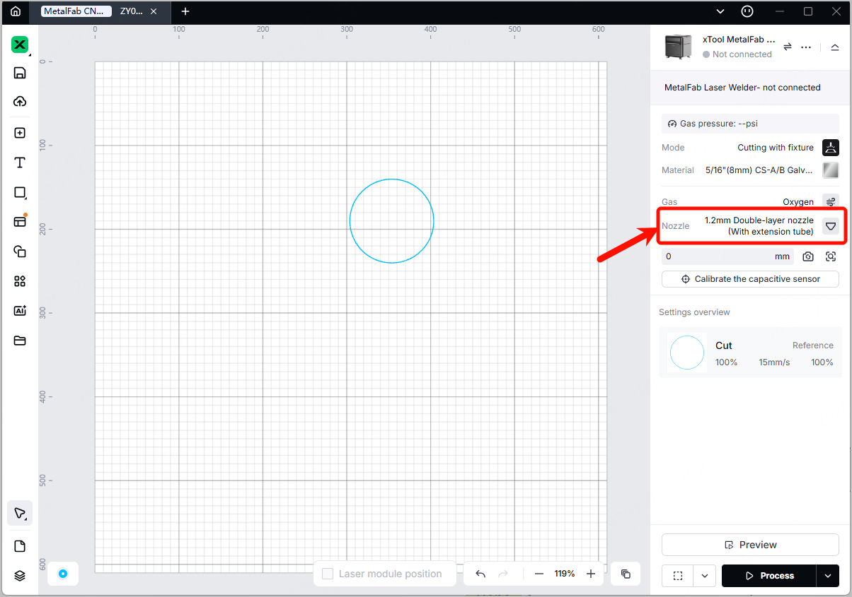
- If an extension tube is needed, install it by following the instructions in How to install a new nozzle.
Note: You can purchase the extension tube and the double-layer nozzle on xtool.com.
Step 3: Adjust the cutting tip knob
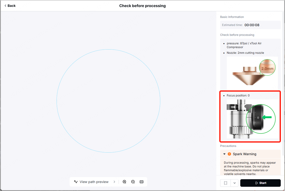
- After clicking Process in xTool software, you may notice the Focus position on the right panel in the Check before processing page.
- Check if the value next to Focus position is within the range [-10,5]
- If yes, turn the cutting tip knob to the required scale value. For details, visit How to Adjust the Cutting Tip Knob.
- If not, proceed to Step 4.
(Optional) Step 4: Adjust the U-shaped component
If the value next to Focus position exceeds the range [-10,5], turn the cutting tip knob to its minimum value -10 or maximum value 5, then adjust the U-shaped component accordingly.
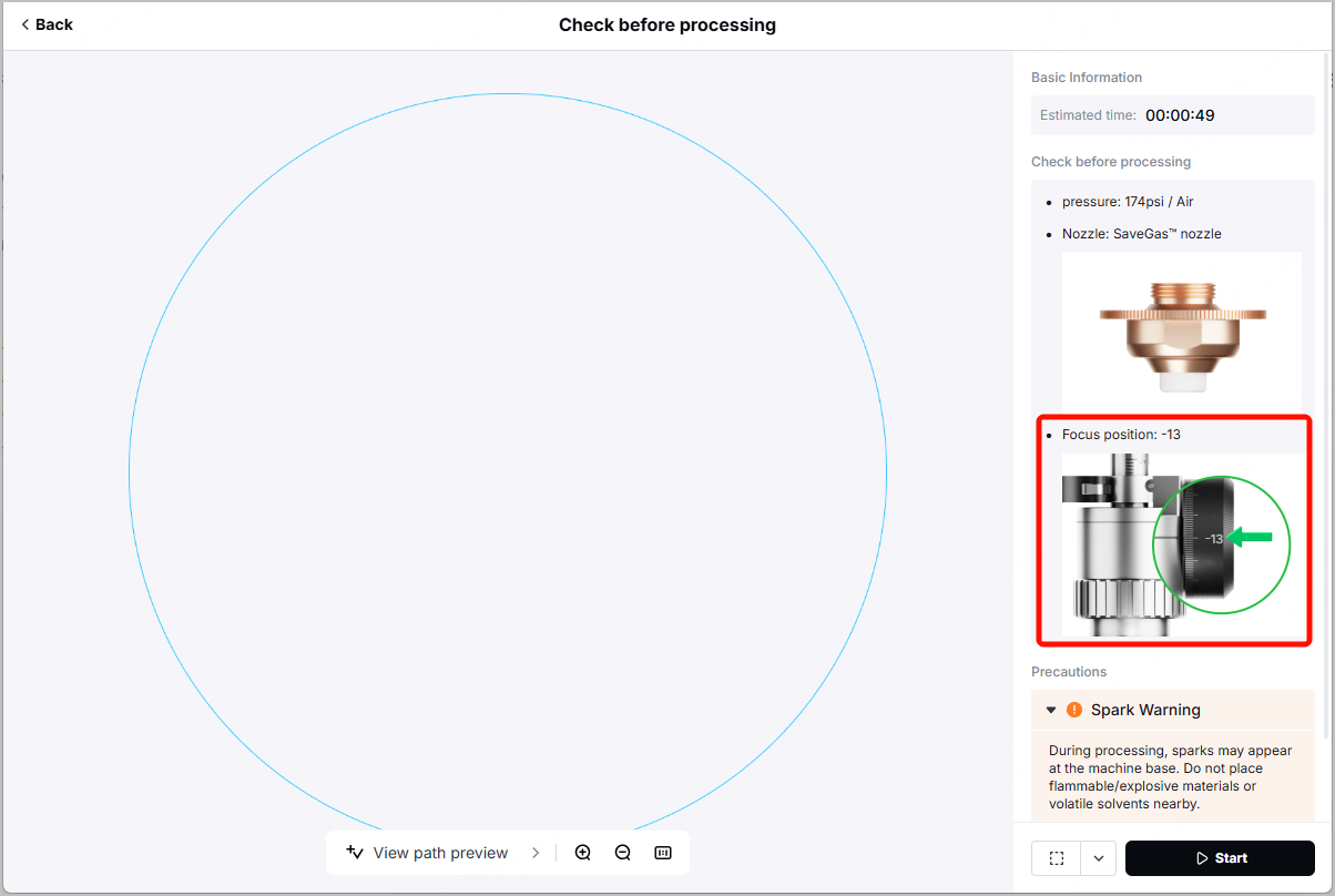
For example, the value is -13. The adjustment steps include:
- Turn the cutting tip knob to -10.
- Adjust the U-shaped component. Specifically, lower the U-shaped component by 3.
For example, if the U-shaped component is at the value 1, lower it to the value -2.
Note: After processing the material that requires Focus position exceeding the range [-10,5], remember to reset the U-shaped component to the value in Step 1.
For example, if the U-shaped component was at the value 1 in Step 1 (welding head calibration), and is lowered to the value -2 to cut a certain material, please remember to lift it back to the value 1 after processing.
Examples
Example 1: Focus position = 0 (Cutting 0.5 mm ASTM-A36 carbon steel)
In the Check before processing page, the recommended focus position for this carbon steel is 0, and an extension tube is not needed. Therefore,
- Ensure that no extension tube is installed.
- Ensure that the cutting tip knob is turned to the value 0.

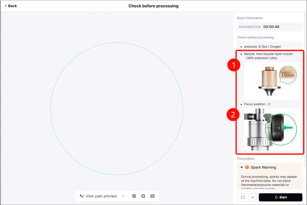
Example 2: Focus position = -2 (Cutting 8 mm ASTM-A36 carbon steel)
In the Check before processing page, the recommended focus position for this carbon steel is -2, and an extension tube is needed. Therefore,
- Ensure that the extension tube is well installed.
- Ensure that the cutting tip knob is turned to the value -2.
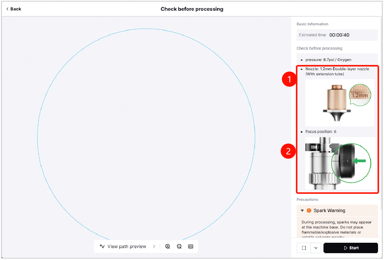
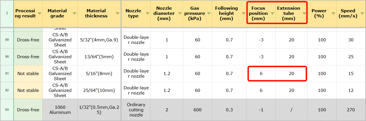
Example 3: Focus position = 6 (Cutting 8 mm CS-A/B galvanized sheet)
In the Check before processing page, the recommended focus position for this carbon steel is 6, and an extension tube is needed. Therefore,
- Ensure that the extension tube is well installed.
- Turn the cutting tip knob to its maximum value, 5.
- Lift the U-shaped component by 1.
For example, if the U-shaped component is at the value 1, lift it to the value 2.
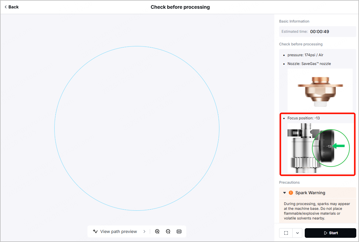
Example 4: Focus position = -13 (Cutting 6 mm 304 stainless steel)
In the Check before processing page, the recommended focus position for this carbon steel is -13, and an extension tube is not needed. Therefore,
- Ensure that no extension tube is installed.
- Turn the cutting tip knob to its minimum value, -10.
- Lower the U-shaped component by 3.
For example, if the U-shaped component is at the value 1, lower it to the value -2.
Note:
1. The maximum range of the U-shaped component is actually [-4,4]. But "-4" and "4" are not engraved on the graduated tube of the cutting tip.
Therefore, if the U-shaped component is at the value -1, you may need to lower the component to -4 based on your observation.
2. DO NOT adjust the U-shaped component to values below -4 or above 4.
Further learning
The preceding chapters have already explained how to adjust to the desired value when the cutting tip knob range is exceeded. If you want to dive into the basic logic behind the adjustment, read the following to gain more information.
Key definitions
Term | Definition & description |
|---|---|
Cutting tip knob range | The cutting tip knob has a range of -10 to +5. If the required defocus amount exceeds this range, follow the adjustment steps in this article to achieve optimal results. |
Defocus amount | Refer to the distance between the laser focus and the material surface. Positive defocus occurs when the focus is above the material surface, while negative defocus occurs when it’s below. Defocus amount = *Extension tube length + Focus position *The extension tube length is defaulted to 20 mm. If no extension tube is needed, please assume it is 0 instead. |
Focus position | Focus position in xTool software and xTool-Recommended Materials and Parameters refers to the sum of cutting tip knob value. If the required value exceeds its standard value range [-10,5], the U-shaped component needs to be adjusted to compensate for the additional value. |
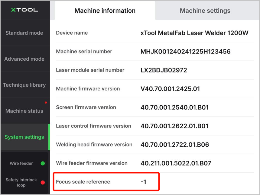
Zero focus | Refer to the scenario where laser focus is exactly on the material surface. The actual zero focus value may differ from "0" due to manufacturing tolerances, despite its name. You can obtain the device's zero focus on your Laser Welder's touchscreen. The value next to Focus scale reference indicates the zero focus value.
|
Note: The values listed in the table of xTool-Recommended Materials and Parameters for xTool MetalFab CNC Cutter (Complete Version) assume that the device's zero focus is exactly 0.
If your device’s zero focus differs from 0, begin by adjusting the U-shaped component. For instruction details, visit xTool MetalFab CNC Cutter - Unboxing and First Use and watch the video from 10:38.
Calculation logic for example 3
In the xTool-recommended materials and parameters table, the recommended focus position for this carbon steel is 6, and the 20 mm extension tube is needed.
- Before any calculation, ensure that the device's zero focus is 0 or "adjusted" to 0.
- If zero focus = 0, proceed to the next step.
- If zero focus ≠ 0, adjust the U-shaped component first.
For example, if the device's zero focus is -1, you need to adjust the U-shaped component to -1, so as to compensate for the manufacturing tolerances.
- Install the 20 mm extension tube.
- Turn the cutting tip knob to its maximum value, 5.
However, since the value in Focus position (mm) is 6, and 6-5=1, we still need an additional 1. - Adjust the U-shaped component. Add 1 to its current value.
For example, if the U-shaped component is now at the value -1, since -1+1=0, we need to adjust the component to the value 0.
The following table shows the calculation based on different scenarios.
Scenario | Zero focus < 0 | Zero focus = 0 | Zero focus > 0 | |
Adjustment steps |
| Example: zero focus=-1 Adjust the U-shaped component to -1. | Ensure that the U-shaped component value is 0. | Example: zero focus = 2 Adjust the U-shaped component to 2. |
| Install the extension tube on the cutting tip. | |||
| Turn the cutting tip knob to its maximum value, 5. Since 6 (focus position) -5=1, we still need an additional 1. | |||
| -1+1=0 Adjust the U-shaped component to 0. | 0+1=1 Adjust the U-shaped component to 1. | 2+1=3 Adjust the U-shaped component to 3. | |
Related links
- xTool-Recommended Materials and Parameters for xTool MetalFab CNC Cutter (Complete Version)
- xTool MetalFab CNC Cutter - Unboxing and First Use
- User Guide for xTool MetalFab CNC Cutter
- How to Adjust the U-shaped Component of the Cutting Tip
- How to Adjust the Cutting Tip Knob
- How to Install the Extension Tube
