1. Set up the slide extension
(1) In the package of the slide extension, take out the movable ruler, which is used to position the laser beams and the objects. Adjust the ruler position according to the length of the objects.
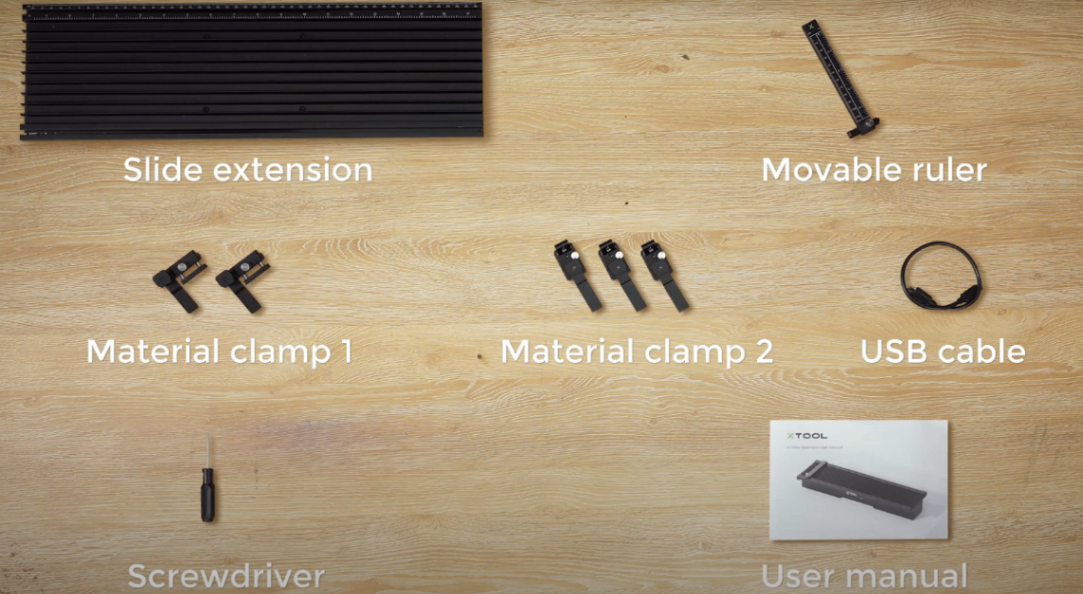
(2) Take out the material clamps, which are used to secure the material. Slide material clamp 1 into the X-rail, lift the fixer, and fix it to the corner of your material. When processing large materials, the material clamp 1 occupies minimal space, as it can be slid into the side rail of the slide extension.
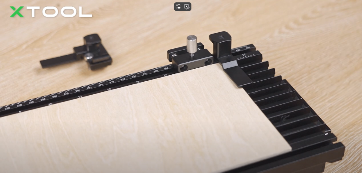
(3) Take out the material clamp 2 and clamp it into the cutting panel. You can also lift the fixer and secure the edges of the material.
2. Connect the slide extension to xTool F1/F1 Lite
Use the USB cable to connect the slide extension to xTool F1/F1 Lite.
3. Connect xTool F1/F1 Lite to xTool Studio
Refer to Connect and Set Up xTool F1/F1 Lite with xTool Studio for instructions on connecting xTool F1/F1 Lite to xTool Studio.
4. Select the processing mode and material
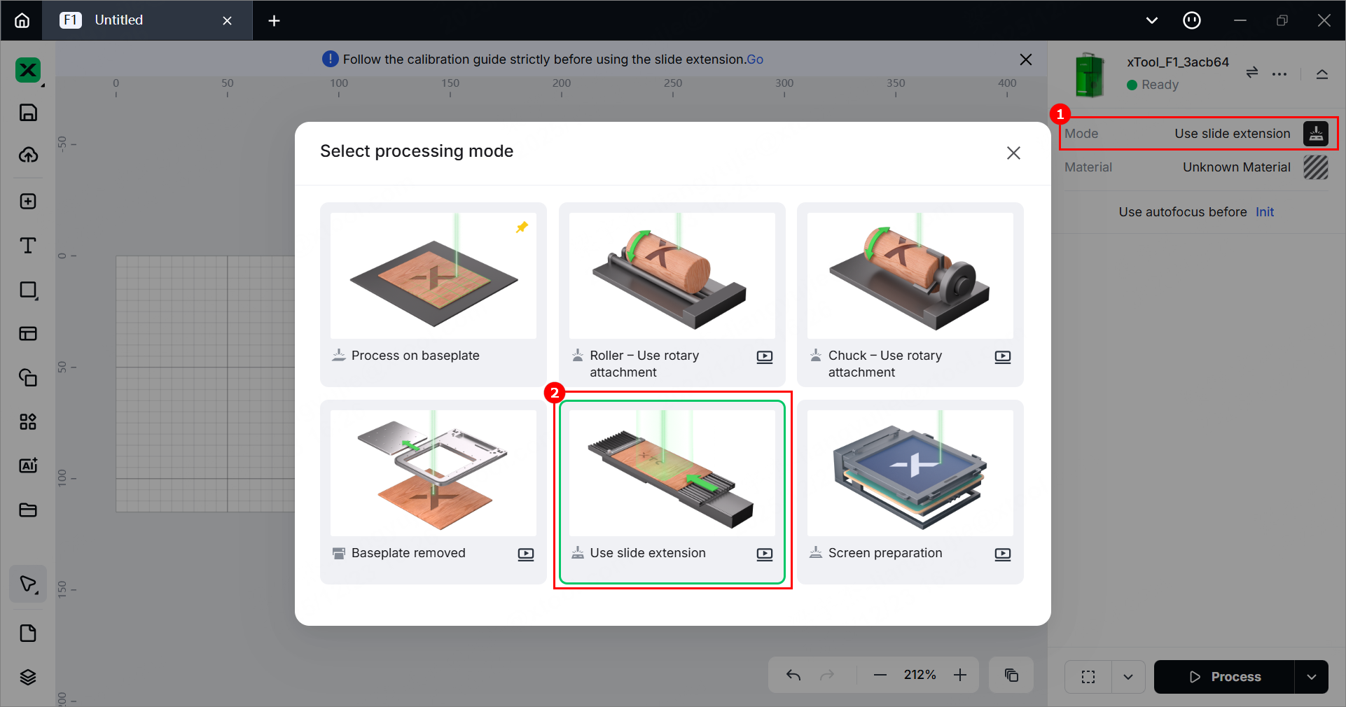
(1) In the right panel, click the current processing mode, and then select Use slide extension.
(2) Click Unknown Material, select the desired material, and click Apply.
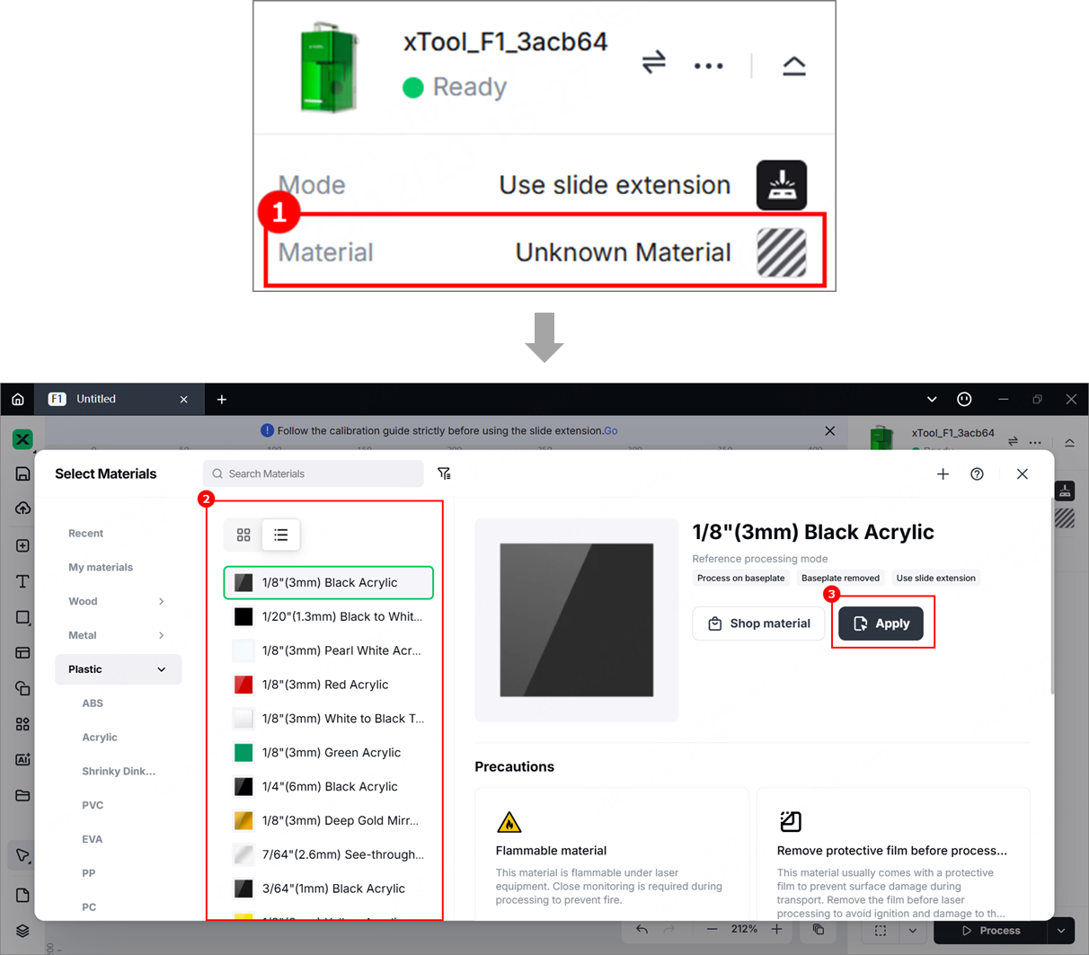
Note: The recommended parameter settings can achieve the best results only when using xTool materials. For third-party materials, it is recommended that you conduct a material test array first to determine the appropriate effects and parameters. Ensure that the materials are free from moisture or contamination, as these factors can significantly affect processing quality.
5. Laser calibration
Follow the calibration guide strictly before using the slide extension. Click Go to start the calibration.
(1) Align the right edge of the movable ruler with scale 0 of the slide extension. Tighten the screw.
(2) Align the vertical line on the side of the slide extension with the edge of the removable baseplate of xTool F1/F1 Lite and align the side of the slide extension with the second line on the baseplate. Move the ruler to the working area. Turn the knob to set the laser focus.
(3) Start laser calibration.
Slightly move the slide extension left or right to align the laser with the center of the movable ruler. Turn the knob to set the laser focus.
(4) Pre-lock
Tighten the screws on the left and right sides, but do not tighten them fully.
(5) Move the slide extension to the left or right, and slightly align the laser with the middle of the movable ruler.
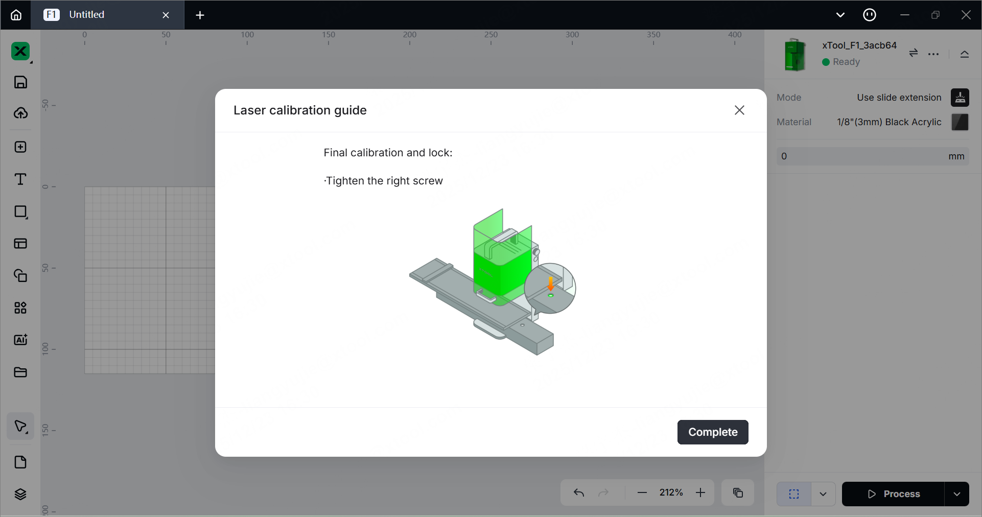
(6) Tighten the left screw, click Next, and the extension will move to the left automatically. Then, tighten the right screw.
(7) Click Complete when you finish calibration.
6. Place the material
(1) Place the material on the slide extension. You can place a single large material or multiple materials evenly on the extension.
(2) Use the material clamp to fix the material.
7. Set the laser focus
xTool F1/F1 Lite supports manual focusing and autofocusing. You can select the desired focusing method.
For optimal cutting results, set the focus point at the midpoint of the material’s thickness.
- Example: To cut 6 mm basswood in a single pass, set the focus point 3 mm below the surface.
- Procedure: First, focus on a 3 mm thick material. Without changing the focus setting, replace it with the 6 mm basswood to be cut.
Manual focus setting
Turn the knob to move the laser module up and down. When the red and blue light spots coincide, the focus is correctly set.
Note:
- If you turn the knob clockwise, the laser module will move up, and the red light spot will move toward the left.
- If you turn the knob counterclockwise, the laser module will move down, and the red light spot will move toward the right.
Note: When the bottom of the laser module reaches the highest point, stop turning the knob up.
Auto focus setting
(1) Measure the material thickness manually with a measuring tool.
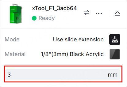
(2) Enter your measurement result in the top-right corner of xTool Studio to allow the device to automatically adjust the focus.
Note:
- When using Auto Focus for the first time after powering on xTool F1/F1 Lite, you must initialize the device to return the laser module to its original position.
- To do this, click Init in the top‑right corner of xTool Studio. The laser module will move back to its default position automatically.
8. Design objects for processing
(1) Use the tools on the left side of the canvas to create objects. You can import images, insert shapes, enter text, or draw vector graphics.
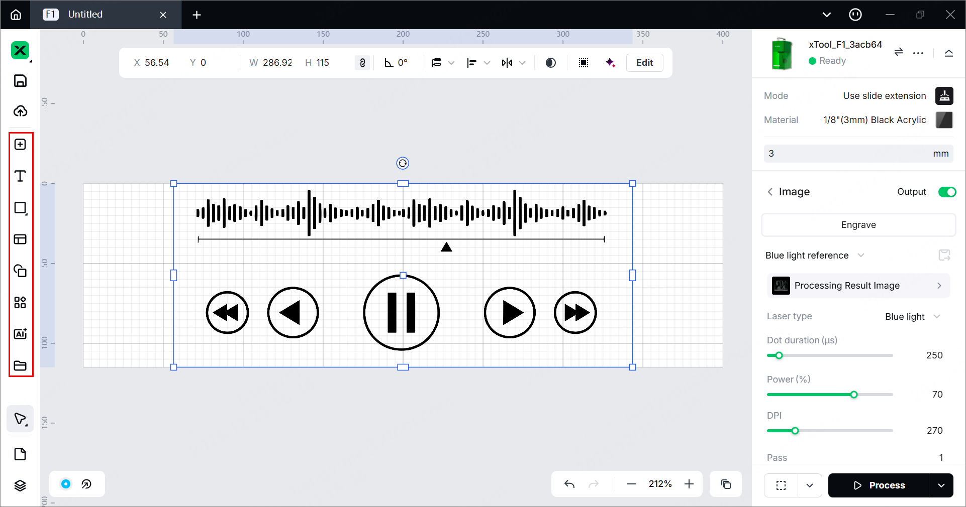
Note: xTool Studio supports importing the following image formats: SVG, DXF, JPG, JPEG, PNG, BMP, etc.
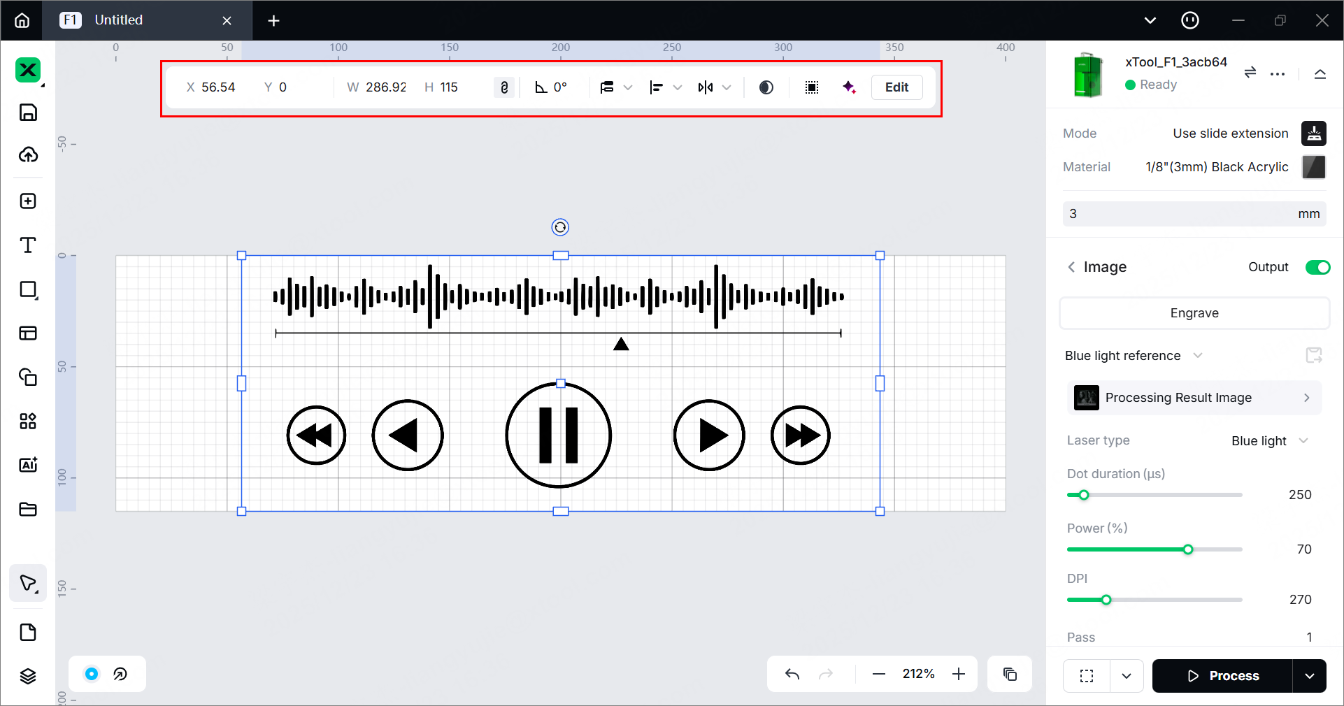
(2) After selecting the objects, use the tools above the canvas for further editing.
9. Set parameters for processing
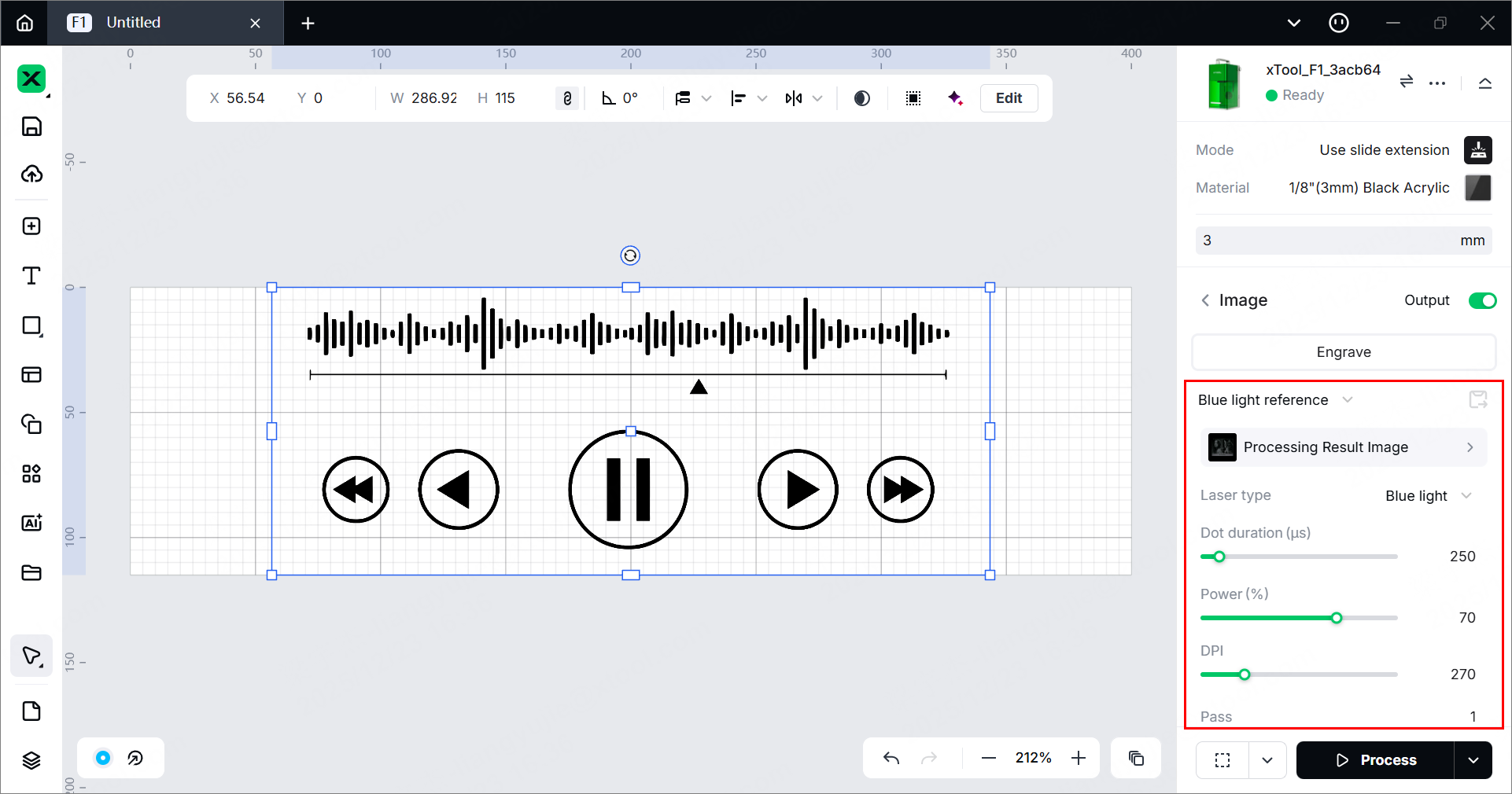
Select objects on the canvas and set their parameters in the right panel.
Note:
- You need to set parameters for every object. A missed object may fail to be processed.
- Parameter options differ between bitmap objects and vector objects. You can select multiple objects of the same type and set parameters for them at once.
Note:
- For xTool F1 Lite, laser type selection is not available, as it has only a blue-light laser.
- For more information on parameter settings, see atomm.com/easyset.
10. Preview the processing area and set the processing path
You can preview the processing area on the material by framing. Framing refers to laser dots moving along the boundary of the processing objects on the material. Perform the following steps to start framing.
(1) Clickin the bottom-right corner of the software and set parameters for framing.
Note: xTool F1/F1 Lite supports two preview modes: Rect and Outline.
- If you select Rect, you can preview the rectangular border of the processing area.
- If you select Outline, you can preview the outline of the processing objects.
(2) Click the framing button in the software or press the framing button on xTool F1/F1 Lite to start framing. The laser spot will move along the boundary of the processing pattern on the material so that you can preview the processing area.
By default, xTool F1/F1 Lite performs framing for all the elements to be processed. To preview the boundary of one or more particular elements, you can select the elements on the canvas of xTool Studio during framing. The laser spot will move along the boundary of the selected elements, as illustrated by the following pictures.
- Default framing:
- Selected elements framing:
If the previewed area is not appropriate, you can adjust the element positions in xTool Studio during framing. xTool F1/F1 Lite will adjust the framing area accordingly, allowing you to preview the processing area in real time.
⚠️ Safety reminder: Before framing, pull down the protective enclosure and wear goggles that can shield laser beams of 455 nm and 1064 nm wavelengths.
Note: To stop framing, click in the software or press the framing button on xTool F1/F1 Lite.
(3) Click in the bottom-right corner and set the processing path for processing.
11. Start processing
💡 In low‑temperature environments, enable the infrared ray preheat function to ensure optimal processing results. If preheat is not enabled, the normal processing sequence may produce unsatisfactory bitmap engraving output due to temperature limitations.
- xTool F1 Lite does not support infrared ray preheat
(1) In the bottom-right corner of the software, click Process.
(2) Click Preview Processing Path and to preview the processing path.
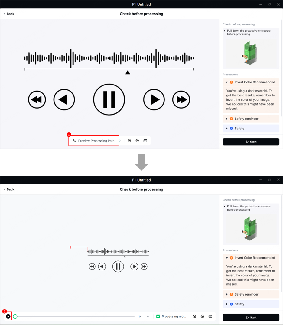
(3) In the bottom-right corner of the software, click Start.
(4) Pull down the protective enclosure. Then, press the knob on xTool F1/F1 Lite to start processing.
⚠️ Safety reminder: Before processing, pull down the protective enclosure and wear goggles that can shield laser beams of 455 nm and 1064 nm wavelengths.