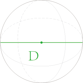
xTool S1 can be used with rotary attachment 2 (RA2) to process cylindrical materials, and be used with rotary attachment 2 pro (RA2 Pro) to process spherical and irregular materials.
Note: To use the rotary attachment on xTool S1, you need to raise the height of xTool S1 with the riser base.
1. Set up the rotary attachment
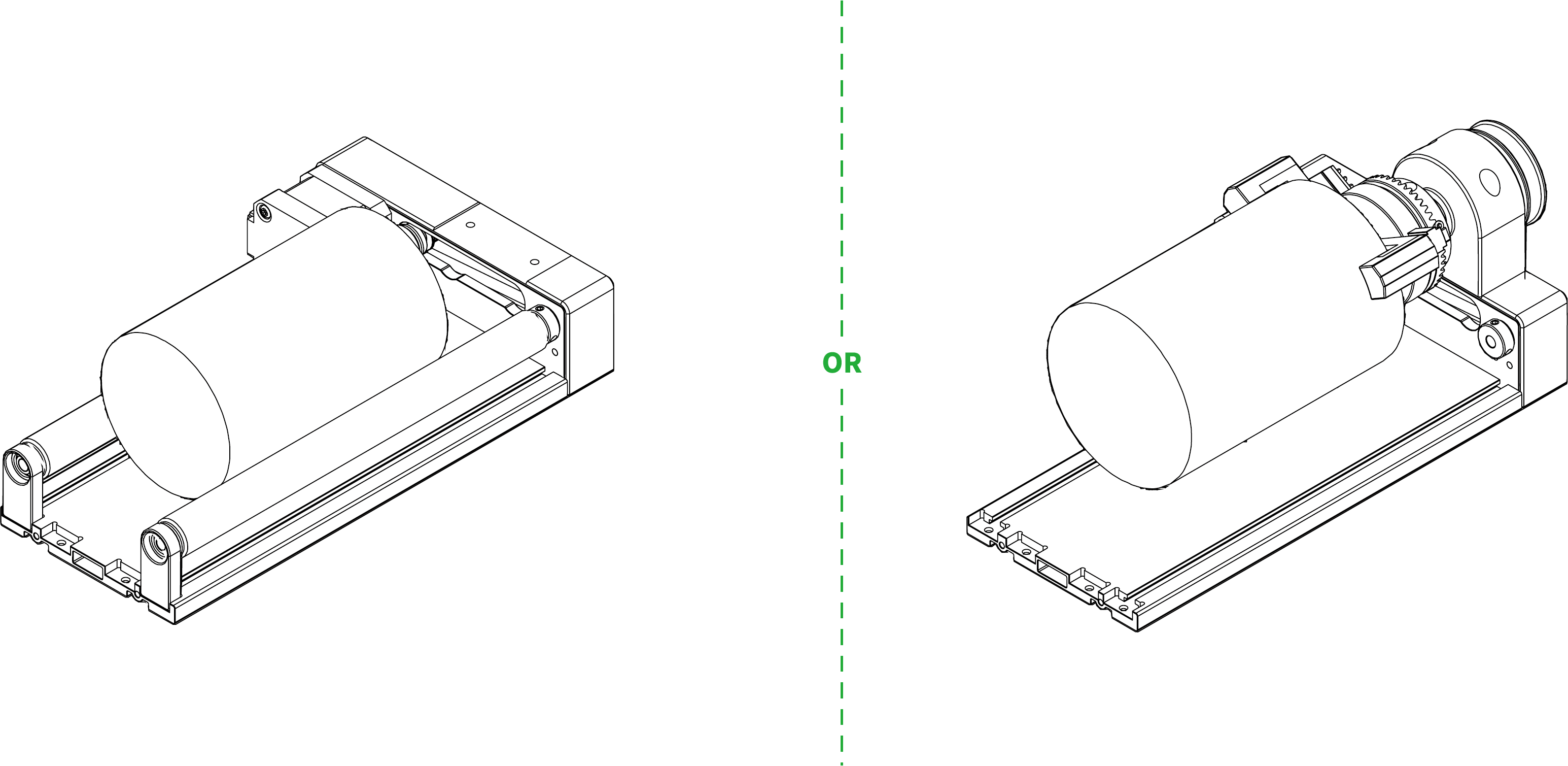
RA2 Pro supports roller mode and chuck mode while RA2 supports only the roller mode.
Assemble and set up the rotary attachment based on your needs.
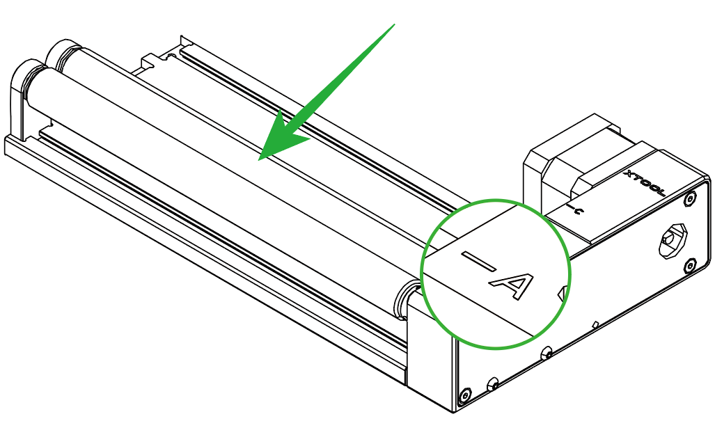
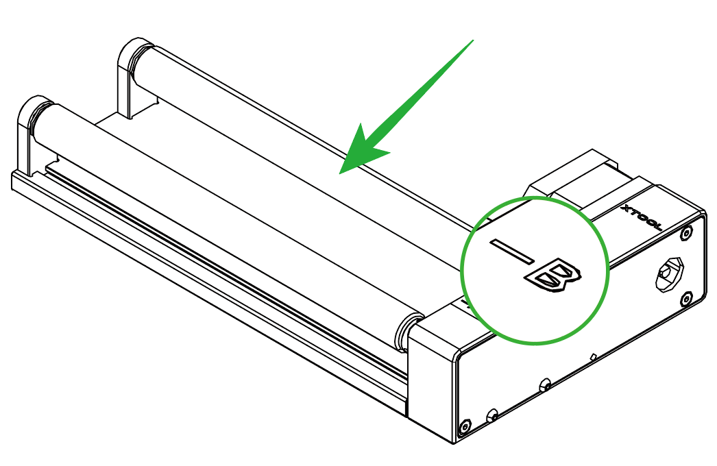
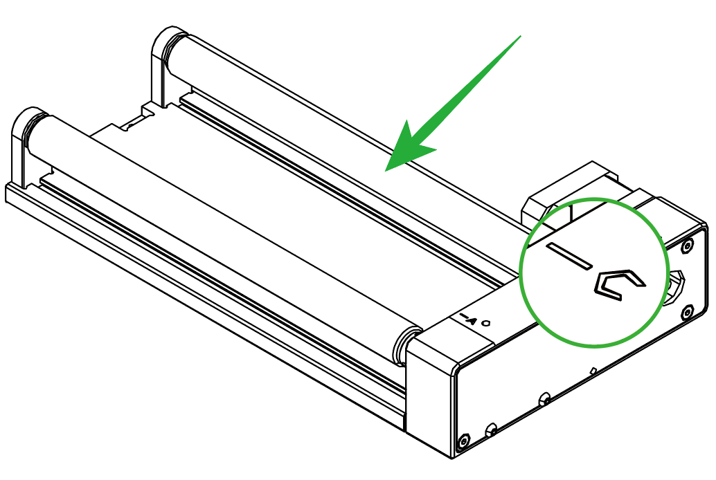
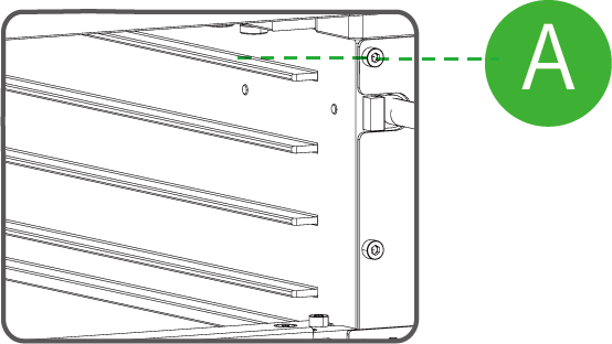
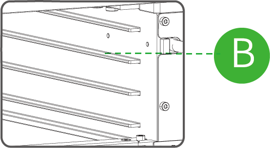
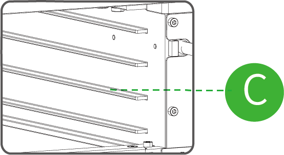
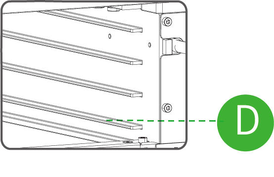
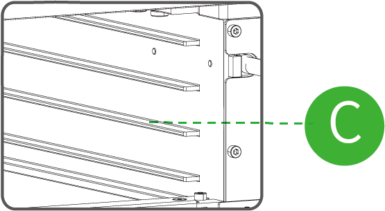
- If you use the roller mode, you can set the rotary attachment to A, B, or C level.
Level A | Level B | Level C |
|---|---|---|
|
|
|
Diameter of material: 3 mm ≤ d ≤ 50 mm | Diameter of material: 45 mm ≤ d ≤ 60 mm | Diameter of material: d > 60 mm |
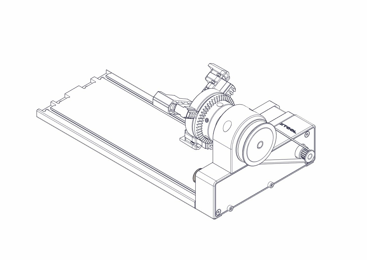
- If you use the chuck mode, you can install jaw chuck components and jaw components as needed.
Note: For detailed information and instructions on how to use RA2, see User Manual for Rotary Attachment 2 (RA2).
2. Power off xTool S1
3. Connect the rotary attachment to xTool S1
Note: The usage of RA2 and RA2 Pro is the same. In this passage, RA2 is used as an example to introduce how to use xTool S1 and rotary attachment for processing.
For ordinary riser base
(1) Insert one end of the connection cable into the rotary attachment.
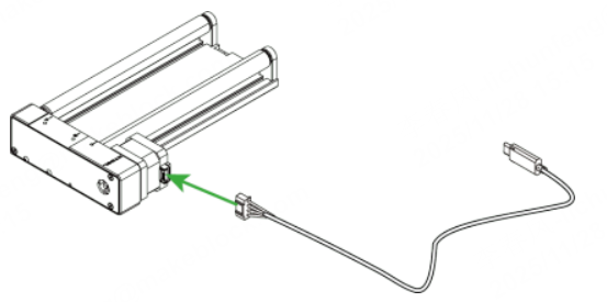
Note: If the connection cable included in the rotary attachment pack is incompatible with xTool S1, you need to purchase a compatible one.
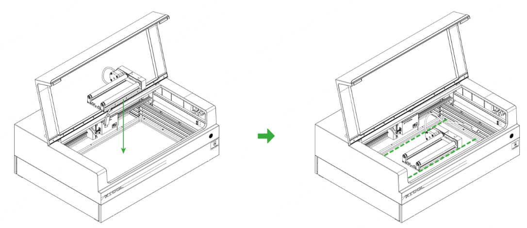
(2) Place the rotary attachment in the processing area of xTool S1. Ensure that the long bottom edges of the rotary attachment are parallel to the front and rear bottom edges of xTool S1.
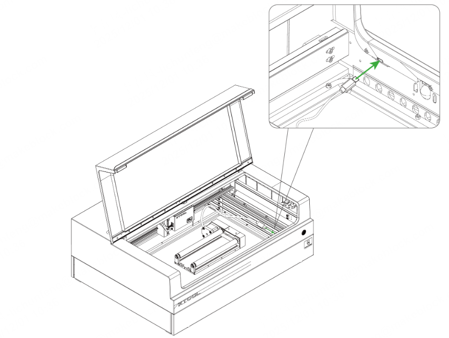
(3) Insert the other end of the connection cable into the extension port on the inner side of xTool S1's front panel.
For the riser base supporting conveyor feeder
(1) The riser base supporting conveyor feeder has four levels of height. You need to determine the level to place the baseplate based on the size of the material.
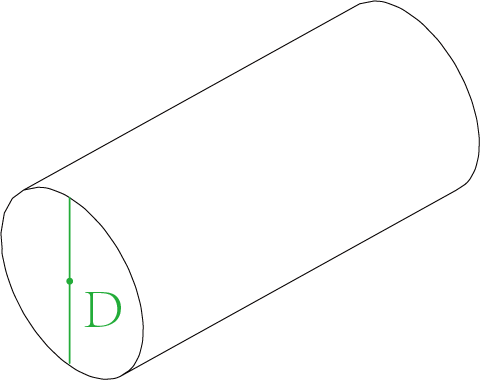
The following table shows how to choose levels for different sizes of materials in different working modes.
Working Mode of RA | Material Diameter | Image |
|---|---|---|
Roller mode
| 3 mm ≤ D ≤ 60 mm |
|
4 mm ≤ D ≤ 72 mm |
| |
20 mm ≤ D ≤ 88 mm |
| |
50 mm ≤ D ≤ 106 mm |
| |
Chuck mode
| 4 mm ≤ D ≤ 82.2 mm |
|
14.2 mm ≤ D ≤ 100 mm |
|

(2) Insert one end of the connection cable into the rotary attachment.
Note: If the connection cable included in the rotary attachment pack is incompatible with xTool S1, you need to purchase a compatible one.
(3) Place the rotary attachment in the processing area of xTool S1. Ensure that the long bottom edges of the rotary attachment are parallel to the front and rear bottom edges of xTool S1.
(4) Insert the other end of the connection cable into the extension port on the inner side of xTool S1's front panel.
4. Power on xTool S1 and connect it to xTool Studio
For more information on how to connect xTool S1 to xTool Studio, see Connect xTool S1 to xTool Studio.
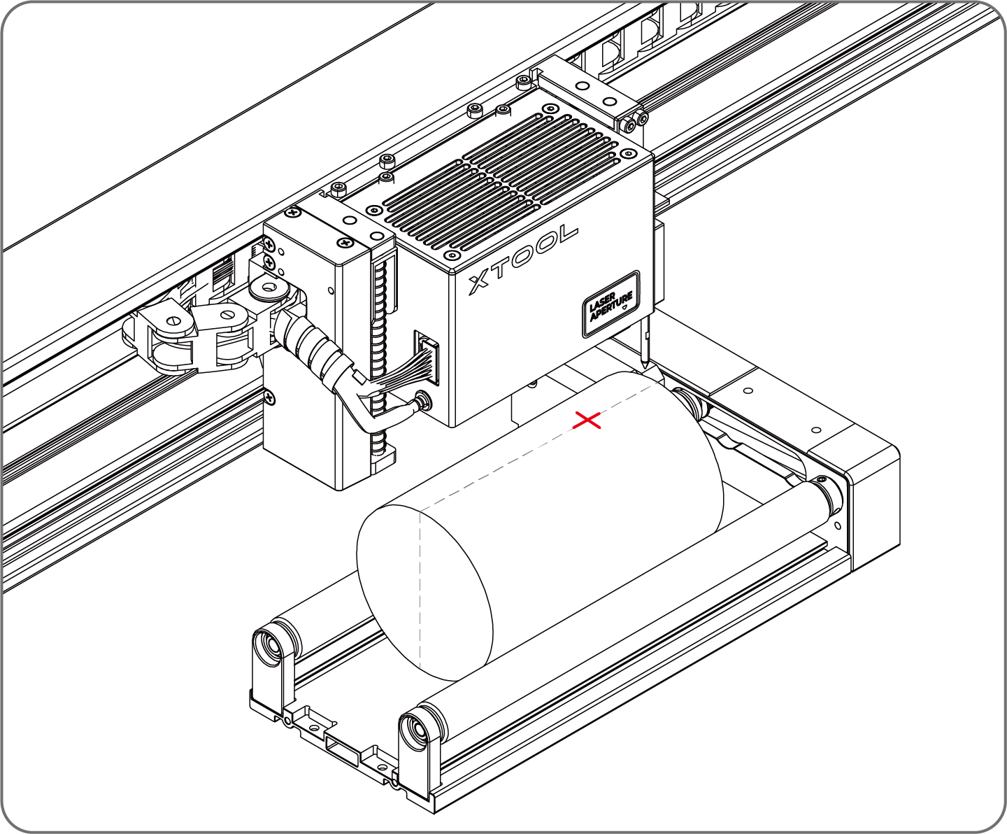
5. Place the material
If you use the roller mode of the rotary attachment, place the material on the rollers. If you use the chuck mode, fix the material on the chuck.
Note: If you use the riser base of the ordinary version, ensure that the top surface of the material is within the processing range of xTool S1. If it is too far away from the laser module, you need to use an object to raise the height of the rotary attachment.
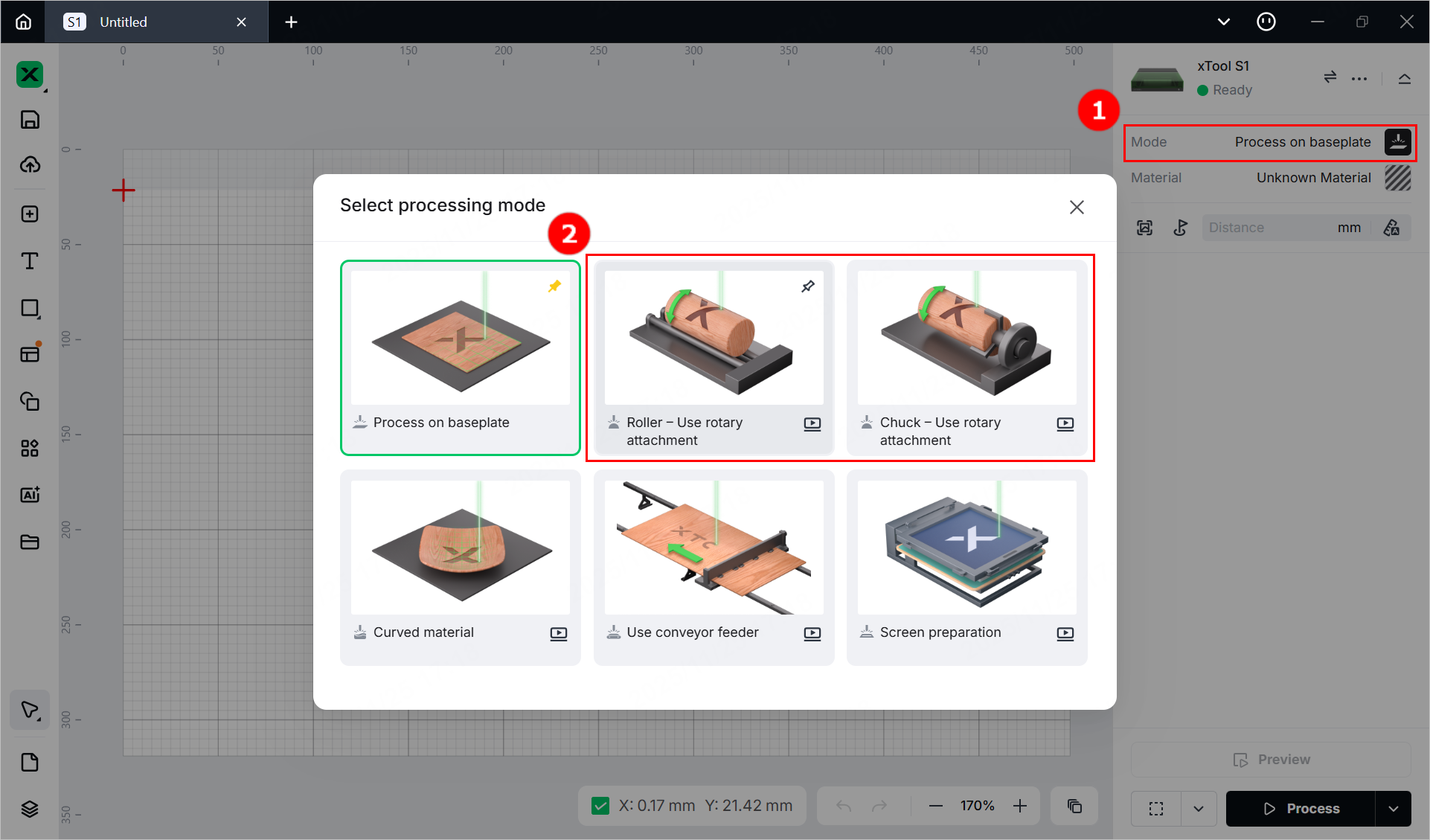
6. Select the processing mode and material
(1) In the right pane of the page, click the name of the current processing mode, and then select Roller - Use rotary attachment or Chuck - Use rotary attachment.
- If you use the rotary attachment in roller mode, select Roller - Use rotary attachment.
- If you use the rotary attachment in chuck mode, select Chuck - Use rotary attachment.
Note: If you select Chuck - Use rotary attachment, you need to enter the Perimeter or Diameter of the material.
(2) Click Unknown Material, select the desired material, and click Apply.
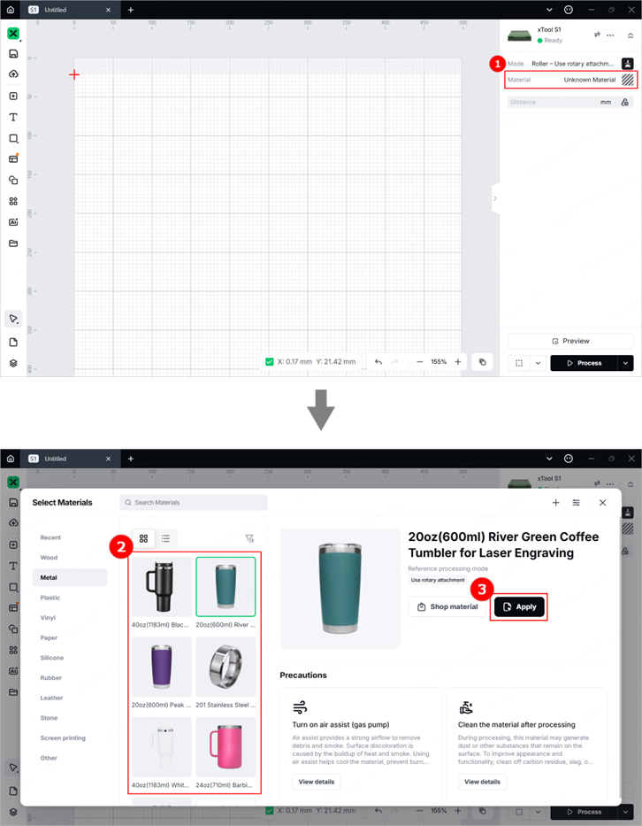
Note: After you select a material from the material list, the software will automatically set parameters for laser processing. The default settings apply to xTool materials. You can adjust the settings based on your needs.
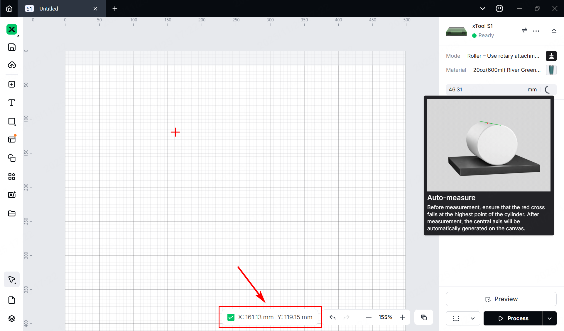
(3) Turn on or off Laser module position based on your need at the bottom of the page.
Note: If you turn on Laser module position, the software will display the position of the laser module in real time. The red cross in the canvas indicates the laser module, and the coordinates of the laser module are shown in the Laser module position section.
7. Set the laser focus
xTool S1 has a distance sensor, which can measure the distance between the laser module and the top material surface. You can also manually measure and calculate the distance between the laser module and the top material surface, and input the obtained values into the software.
During processing, xTool S1 will perform auto-focus based on the Distance parameter.
- Auto measure
(1) Move the laser module over the material. Ensure that the locating spot falls on the top surface of the material.
(2) In the right pane of the page, click the Auto-measure icon. xTool S1 will automatically measure the distance from the laser module to the material surface.
- Manual measure
(1) Use a ruler to measure the distance from the surface of the material to the top of the laser module.
(2) Subtract 100 mm (3.937 inches) from the measured value from step (1), and input the calculated value as Distance.
8. Design objects for processing
(1) Use the tools to the left side of the canvas to create objects. You can import images, insert shapes, enter text, or draw vector graphics.
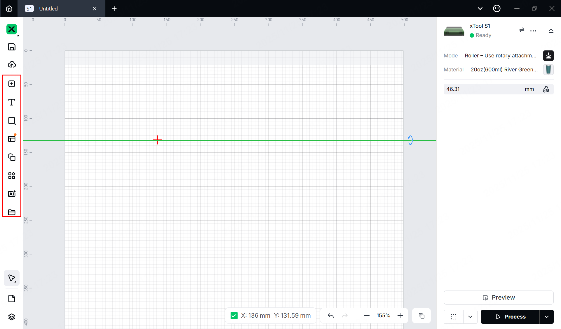
Note: xTool Stuido supports importing the following image formats: SVG, DXF, JPG, JPEG, PNG, BMP, etc.
(2) Select the objects to further edit them using the tools above the canvas.
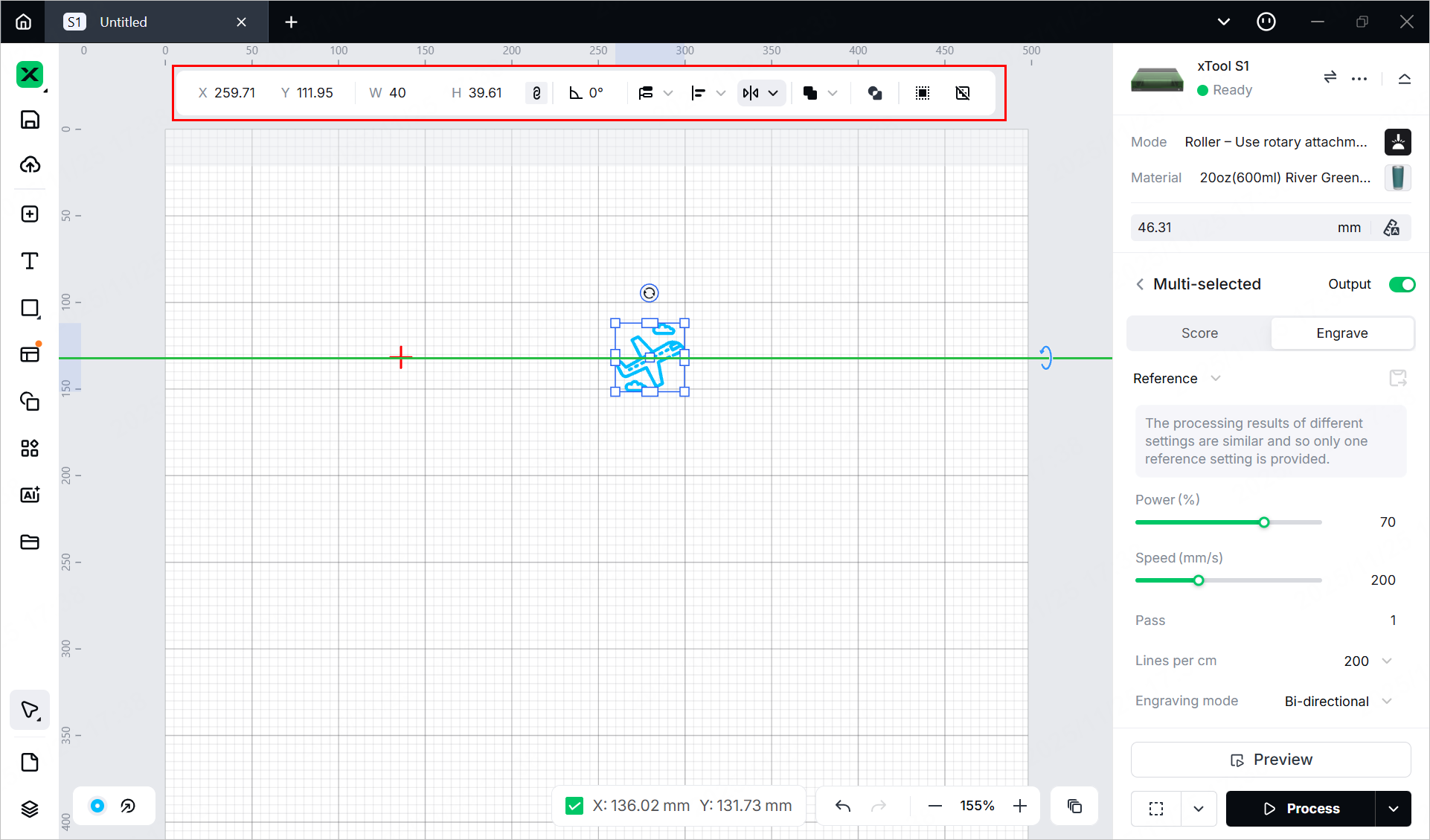
9. Set parameters for processing
Select objects on the canvas and set parameters for them in the right pane.

You need to set parameters for every object. A missed object may fail to be processed.
The parameters that can be set for bitmap objects and vector objects are different. You can select multiple objects of the same type and set parameters for them at once.
Note:
- For a detailed explanation of each parameter, see Software Learning Center.
- For more information on parameter settings, see atomm.com/easyset.
10. Preview the processing area
You can preview the processing area on the material by framing. Framing means laser dots walk along the border of the processing objects on the material. Take the following steps to start framing.
(1) In the bottom-right corner of the software, click next to the Framing button to set parameters for framing.
Note: You can tap the arrow buttons to control the movement of the laser module. The other three parameters allow you to configure how the laser module moves with every tap on an arrow button.
XY speed (mm/s): The moving speed of the laser module in X and Y directions.
XY distance (mm): The moving distance of the laser module with each tap on an XY arrow button.
Z distance (mm): The moving distance of the laser module with each tap on a Z arrow button.
(2) Close the lid of xTool S1, click Framing in the software, and press the button on xTool S1 to start framing. The laser spot will move along the boundary of the processing pattern on the material so that you can preview the processing area.
(3) After the framing is complete, click Framing completed in the software. If the area is not ideal, you can adjust the material position or adjust the element positions in the software, and then preview the processing area again.
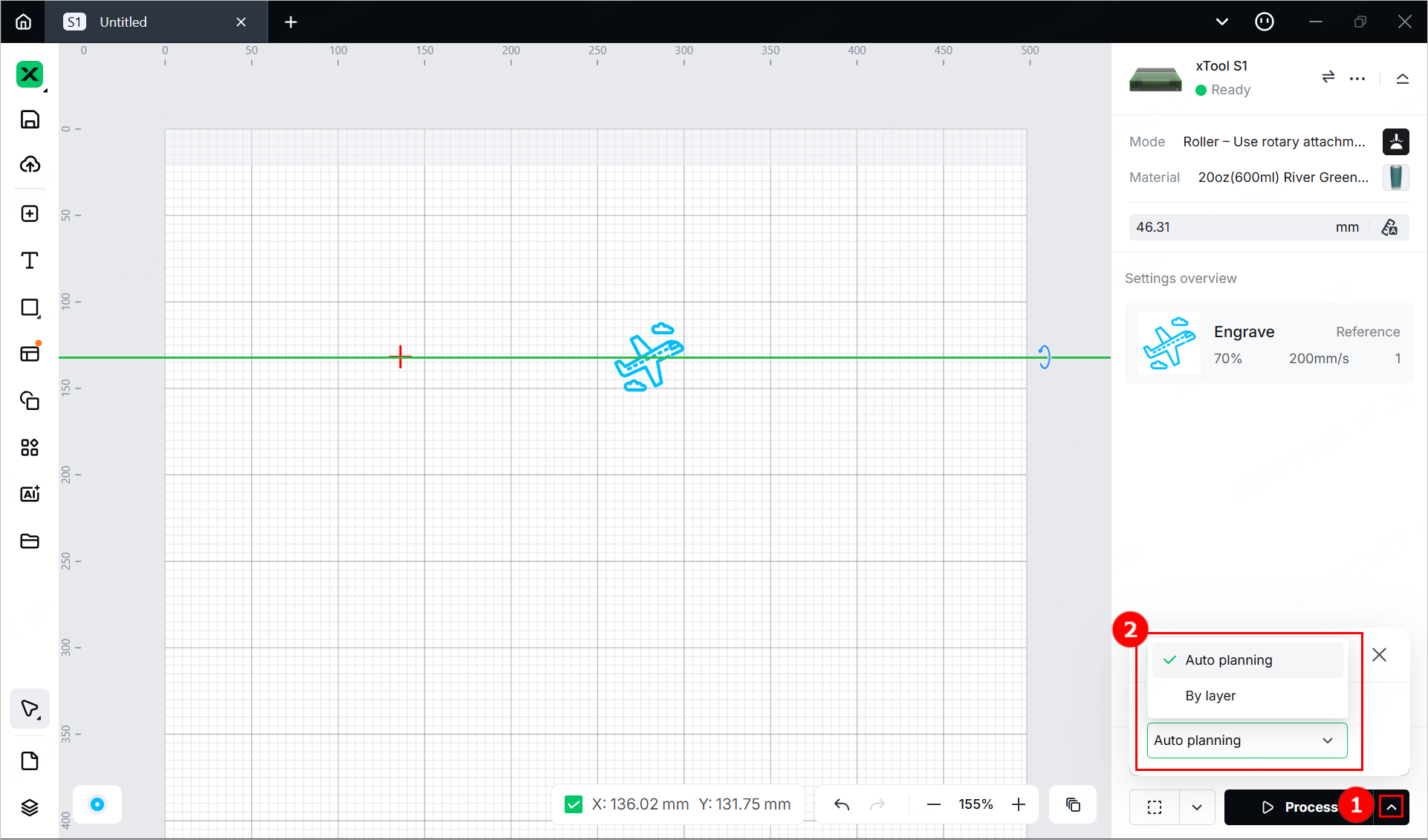
(4) Click in the bottom-right corner and set processing path for processing.
11. Start processing
(1) In the bottom-right corner of the software, click Process.
(2) Click View path preview and to preview the processing path.
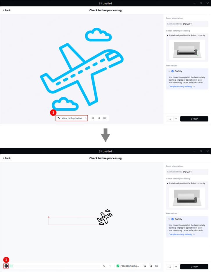
(3) In the bottom-right corner of the software, click Start. Then, press the button of xTool S1 to start processing.
