xTool S1 supports different material thicknesses when working with different accessories. To process a material with curved surfaces, ensure that the overall height of the material does not exceed the supported material thickness.
Combinations of xTool S1 and accessories | Supported material thickness (H) |
xTool S1 | 0 mm < H ≤ 42 mm |
xTool S1 + slats | 0 mm < H ≤ 34 mm |
xTool S1 + honeycomb panel | 0 mm < H ≤ 15 mm |
xTool S1 + riser base | 70 mm ≤ H ≤ 125 mm |
xTool S1 + riser base + honeycomb panel | 0 mm < H ≤ 99 mm |
xTool S1 + riser base supporting conveyor feeder | 15.5 mm ≤ H ≤ 133.5 mm |
xTool S1 + riser base supporting conveyor feeder + honeycomb panel | 0 mm < H ≤ 106.5 mm |
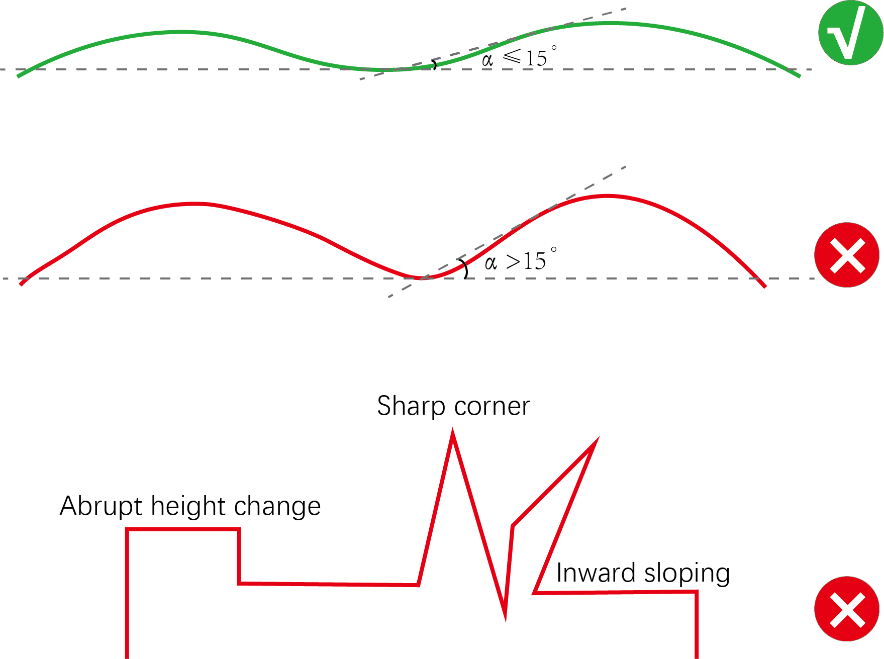
- Supported curve
Please use a material with a smooth surface and gentle curves. Ensure that the angle between the tangent to the curve at any point and a horizontal line is no more than 15 degrees.
1. Connect xTool S1 to xTool Studio
Refer to Connect and Set Up xTool S1 with xTool Studio to connect xTool S1 to xTool Studio.
2. Place the material
Open the lid of xTool S1, and place the material to be processed on the baseplate.
3. Open or create a project
You can open a project to start processing or create a new project. If you create a new project, you need to design patterns and set parameters from scratch.
- Open a project
On the home screen of xTool Studio, click Open. In the pop-up window, select the desired file and click Open.
- Create a new project
On the home screen of xTool Studio, click + New Project.
4. Select the processing mode and material
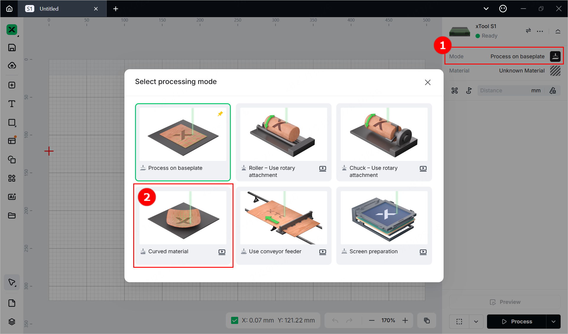
(1) In the right pane of the page, click the name of the current processing mode, and then select Curved material.
(2) Click Unknown Material, select the desired material, and click Apply.
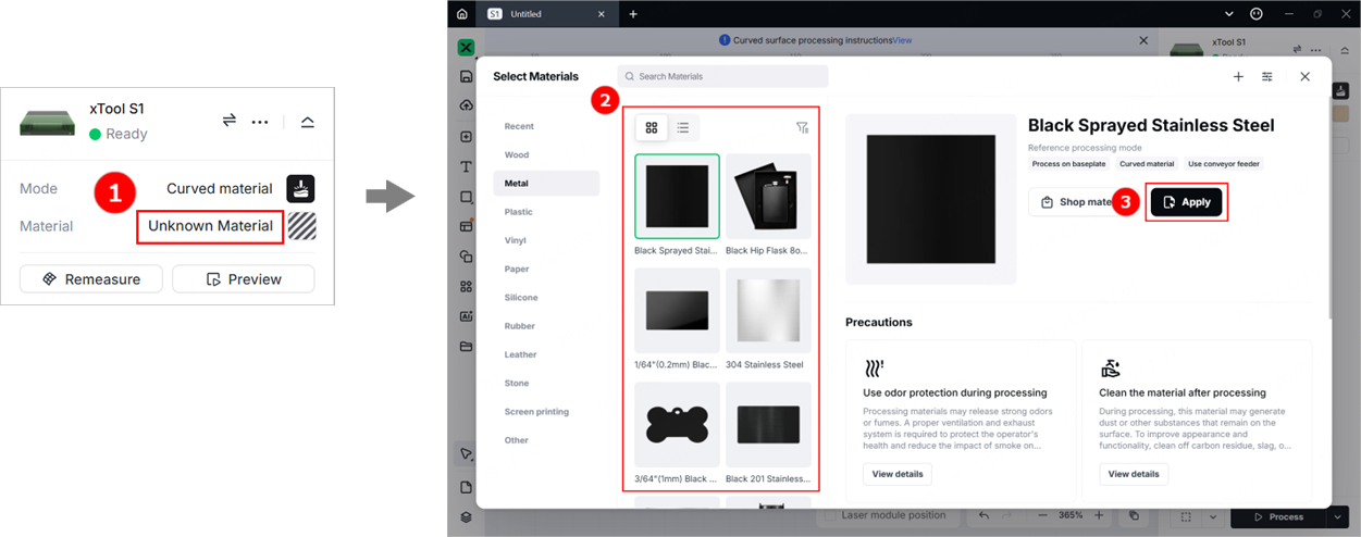
(3) Turn on or off Laser module position at the bottom of the page based on your need.
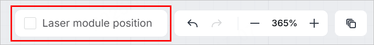
Note: If you turn on Laser module position, xTool Studio will display the position of the laser module in real time. The red cross in the canvas indicates the laser module, and the coordinates of the laser module are shown near Laser module position.
5. Select the target processing area
(1) In the right pane, click Curve-measure.
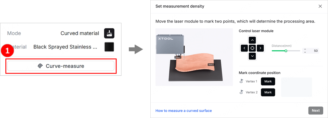
(2) Move the laser module until the locating spot falls on the vertex in the top-left corner of the target processing area. Click Mark to mark it as vertex 1.
Tip: You can manually move the laser module or click the arrow buttons on the software to move the laser module. If you use software control, you can set the distance the laser module moves with each click of the arrow button through Distance.
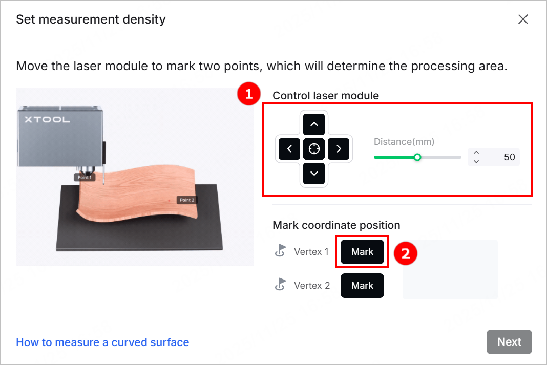
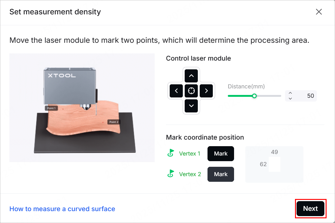
(3) Move the laser module again until the locating spot falls on the vertex in the bottom-right corner of the target processing area. Click Mark to mark it as vertex 2.
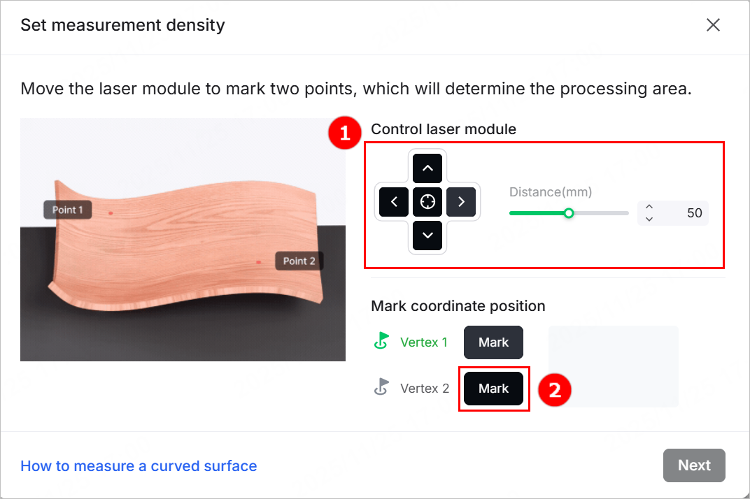
(4) After you finish marking the two vertices, click Next.
6. Set the measurement density
(1) xTool Studio provides recommended measurement density based on the size of the marked area. You can adjust the measurement density as needed.
Tip: The more rows and columns, the higher the measurement density, the more precise the model, and the longer the measurement time.
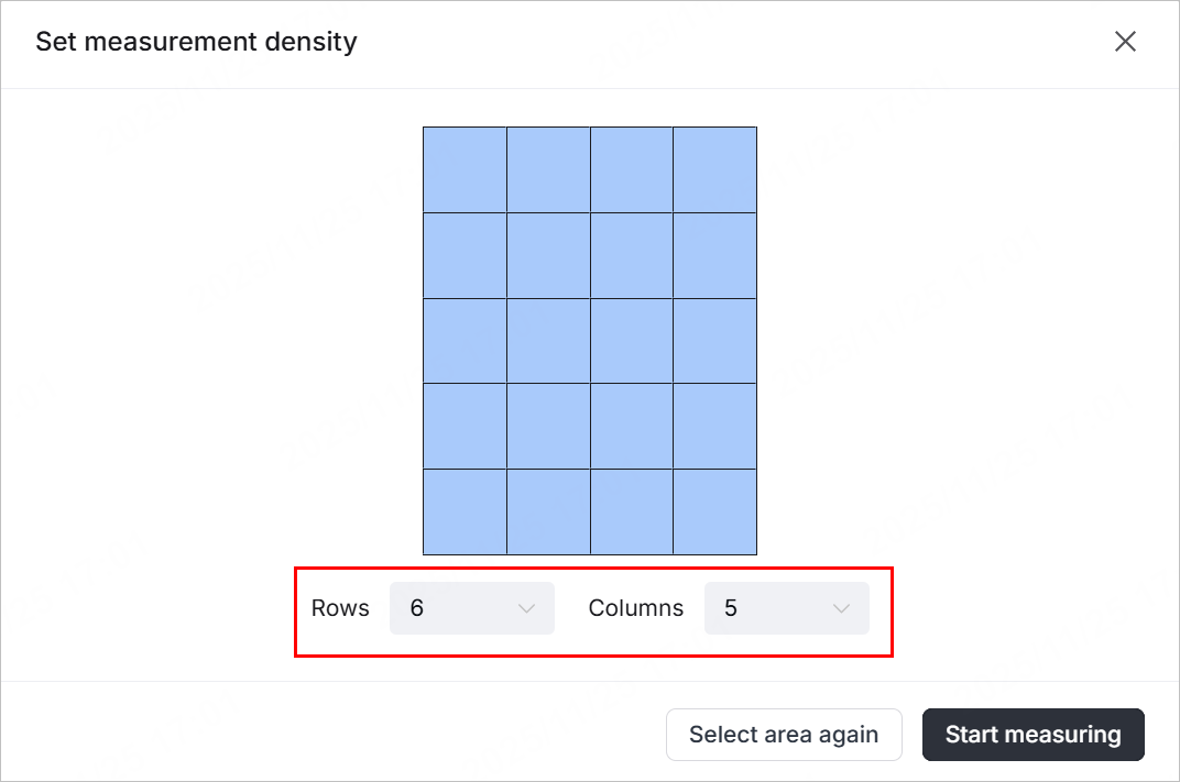
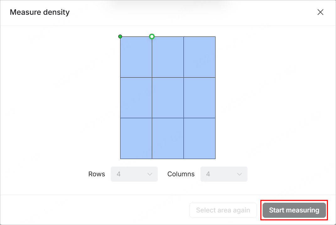
(2) Click Start measuring, and the laser module will measure the height of each point on the selected surface. You can see the measurement progress on the software.
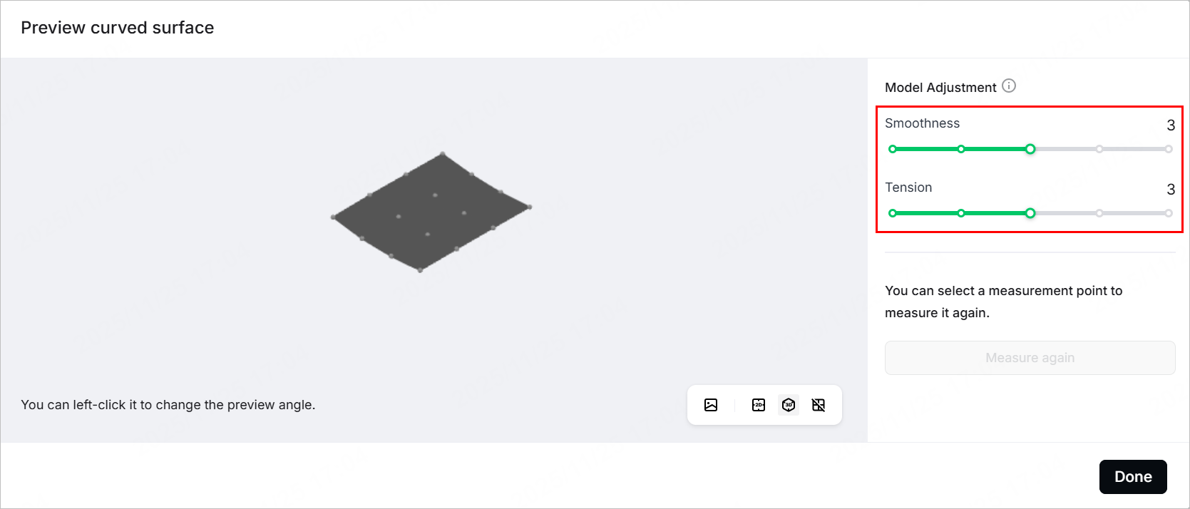
(3) After the measurement is complete, xTool Studio generates a model.
- You can rotate and view the model by dragging it with the mouse and click the buttons in the bottom-right corner to view the model from different angles.
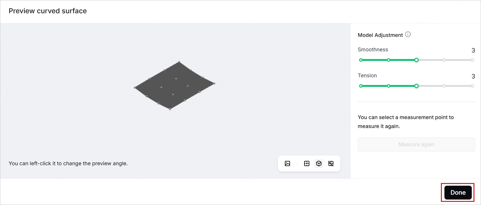
- You can also adjust the Smoothness and Tension of the model to make it closer to the actual object.
(4) Click Done. The selected and measured area is displayed normally on the canvas, while the other area becomes grey.
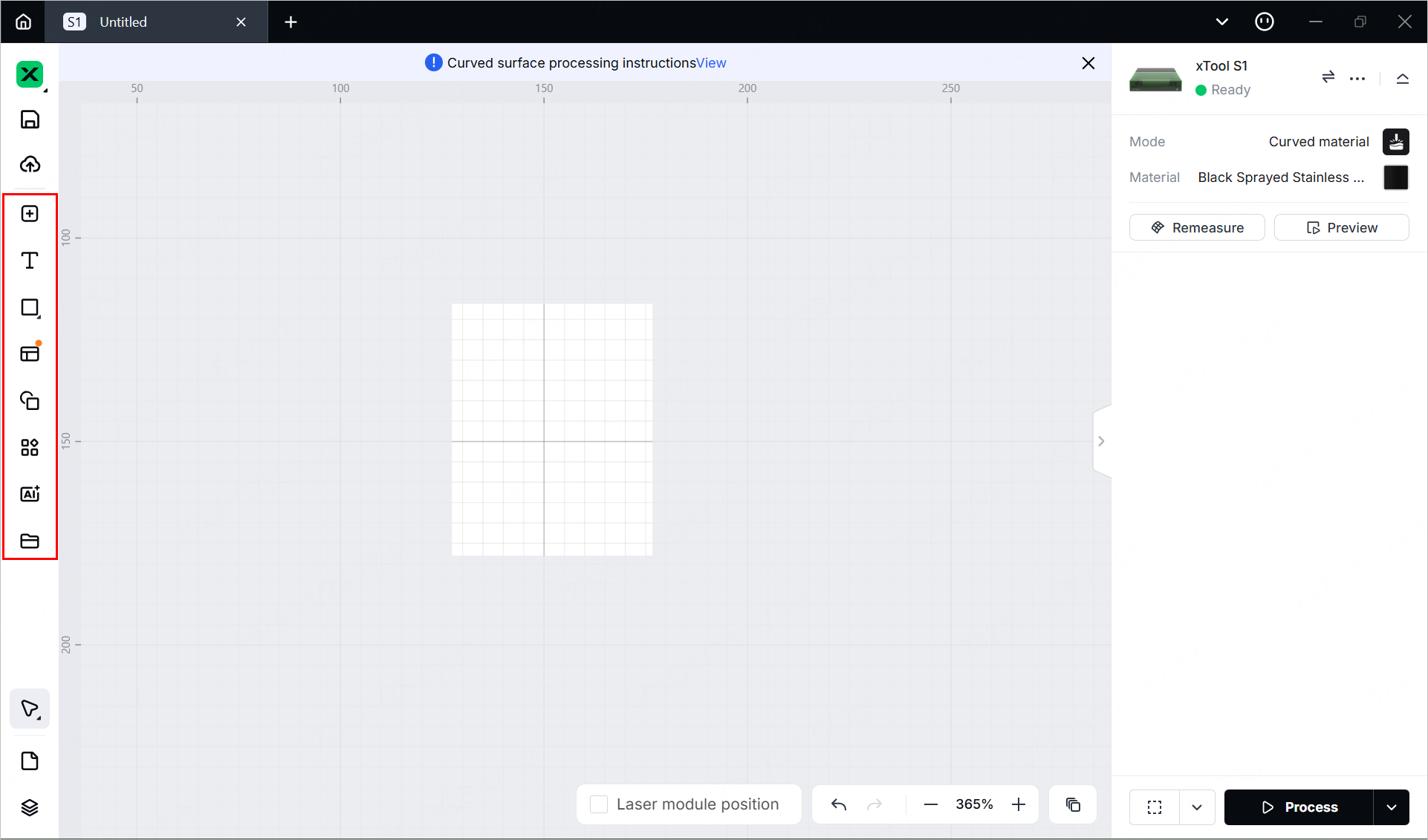
7. Design objects for processing
Note: The gray area on the canvas is an unmeasured area. Do not place processing elements in this area.
(1) Use the tools to the left side of the canvas to create objects. You can import images, insert shapes, enter text, or draw vector graphics.
Note: xTool Studio supports importing the following image formats: SVG, DXF, JPG, JPEG, PNG, BMP, etc.
(2) Select the objects to further edit them using the tools above the canvas.
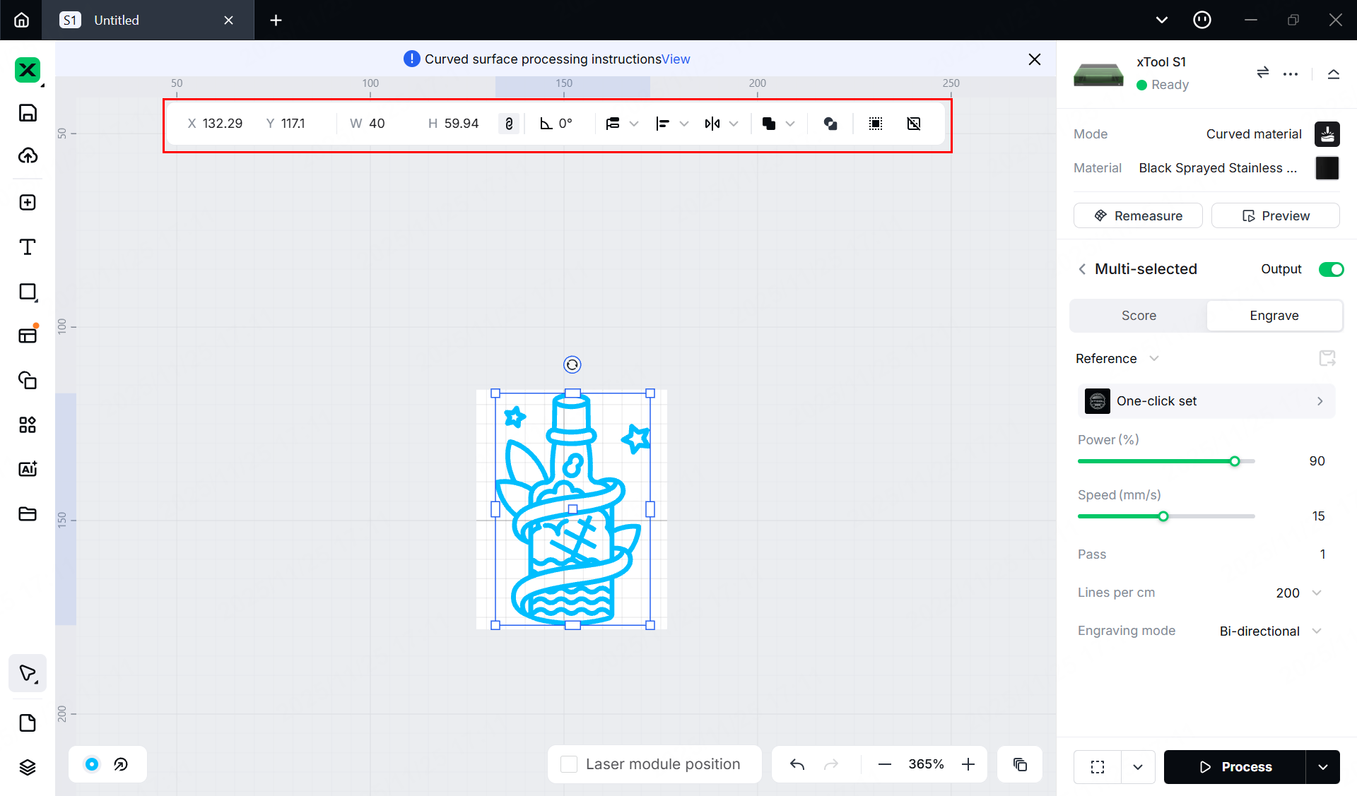
8. Set parameters for processing
Select objects on the canvas and set parameters for them in the right pane of the page.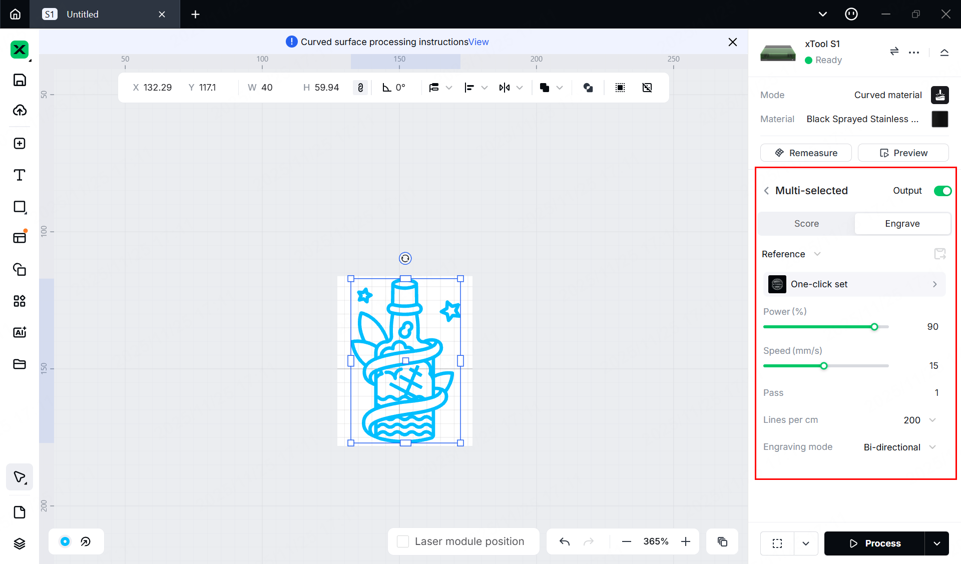
Note:
You need to set parameters for every object. A missed object may fail to be processed.
The parameters that can be set for bitmap objects and vector objects are different. You can select multiple objects of the same type and set parameters for them at once.
For more information on parameter settings, see atomm.com/easyset.
9. Preview the processing area and set the processing path
You can preview the processing area on the material by framing. Framing means laser dots walk along the border of the processing objects on the material. Take the following steps to start framing.
(1) Click in the bottom-right corner of the software and set parameters for framing.
Note: You can tap the arrow buttons to control the movement of the laser module. The other three parameters allow you to configure how the laser module moves with every tap on an arrow button.
XY speed (mm/s): The moving speed of the laser module in X and Y directions.
XY distance (mm): The moving distance of the laser module with each click on an XY arrow button.
Z distance (mm): The moving distance of the laser module with each click on a Z arrow button
(2) Close the lid of xTool S1, and then click the framing button in the software. Press the button on xTool S1 to start framing. The laser spot will move along the boundary of the processing pattern on the material.
(3) After the framing is complete, click Framing completed in the software. If the area is not ideal, you can adjust the material position or adjust the element positions in the software, and then preview the processing area again.
(4) Click  in the bottom-right corner and set processing path for processing.
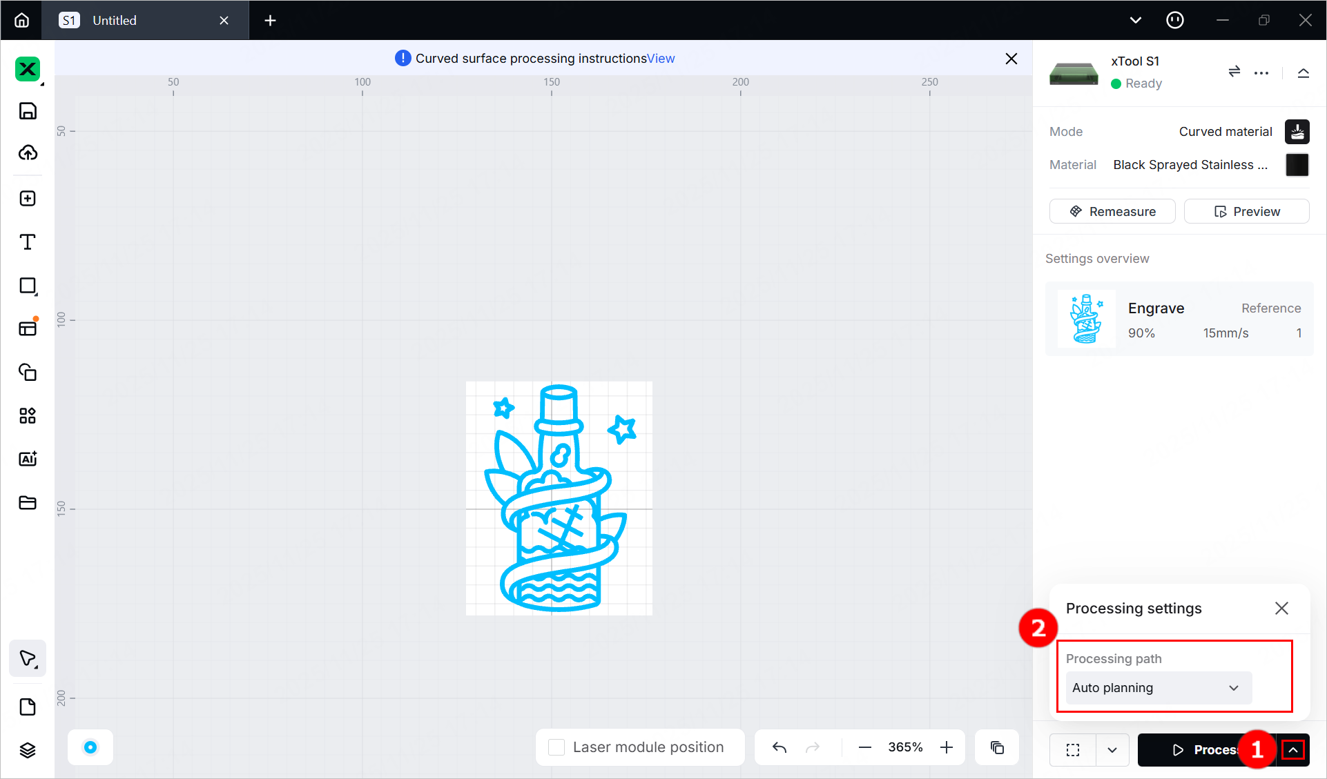
10. Start processing
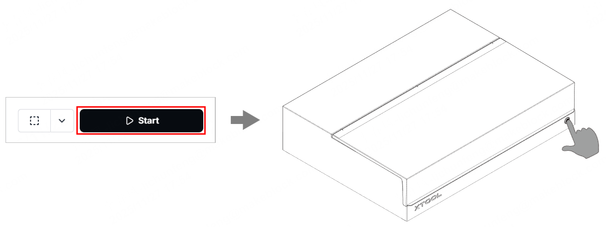
(1) In the bottom-right corner of the software, click Process.
(2) Click View path preview and to preview the processing path.
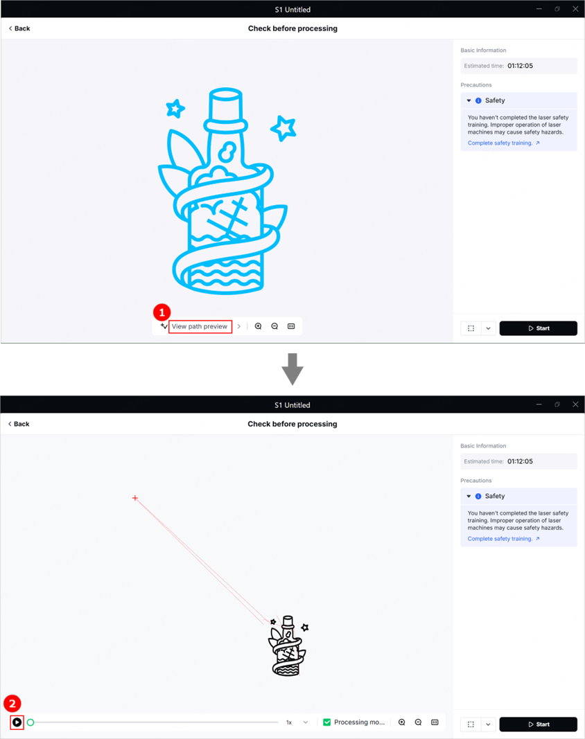
(3) In the bottom-right corner of the software, click Start. Then, press the button of xTool S1 to start processing.