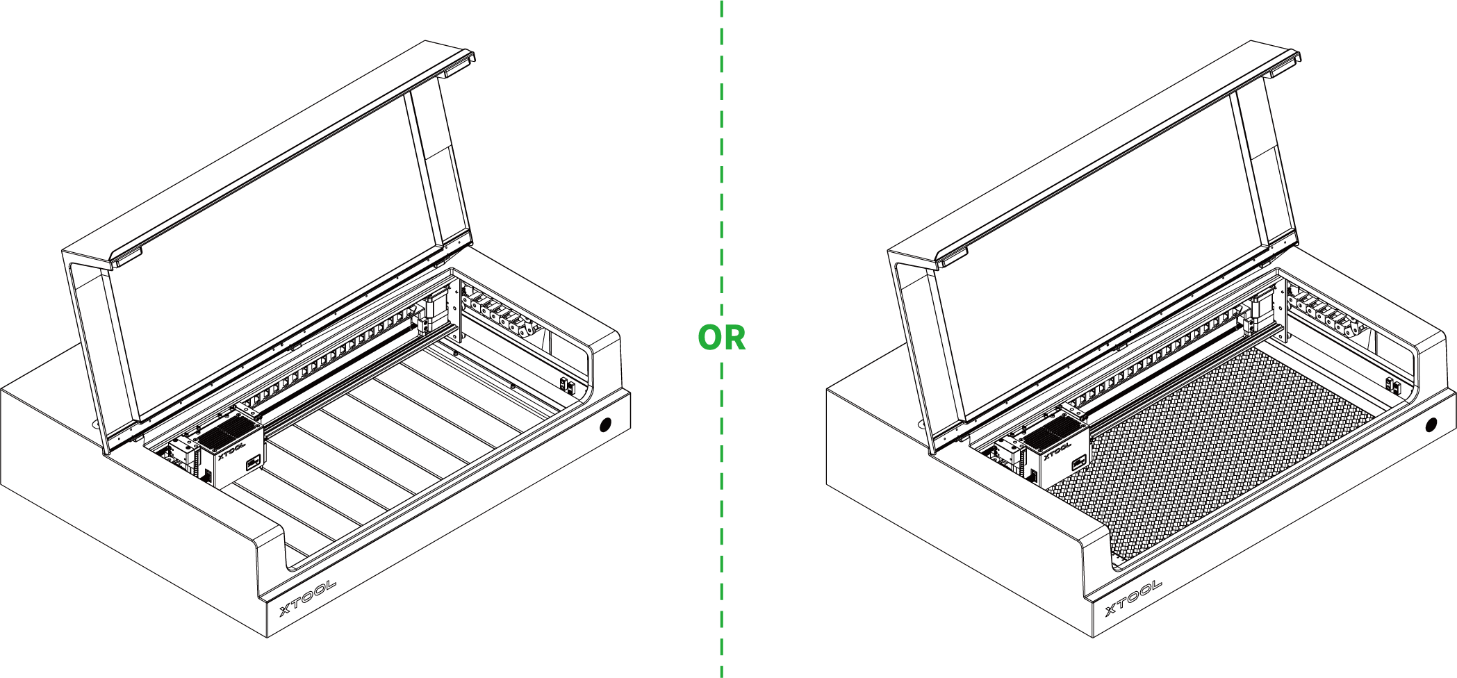
xTool S1 supports different material thicknesses when working with different accessories.
Combinations of xTool S1 and accessories | Supported material thickness (H) |
|---|---|
xTool S1 | 0 mm < H ≤ 42 mm |
xTool S1 + slats | 0 mm < H ≤ 34 mm |
xTool S1 + honeycomb panel | 0 mm < H ≤ 15 mm |
xTool S1 + riser base | 70 mm ≤ H ≤ 125 mm |
xTool S1 + riser base + honeycomb panel | 0 mm < H ≤ 99 mm |
xTool S1 + riser base supporting conveyor feeder | 15.5 mm ≤ H ≤ 133.5 mm |
xTool S1 + riser base supporting conveyor feeder + honeycomb panel | 0 mm < H ≤ 106.5 mm |
1. Connect xTool S1 to xTool Studio
Refer to Connect and Set Up xTool S1 with xTool Studio to connect xTool S1 to xTool Studio.
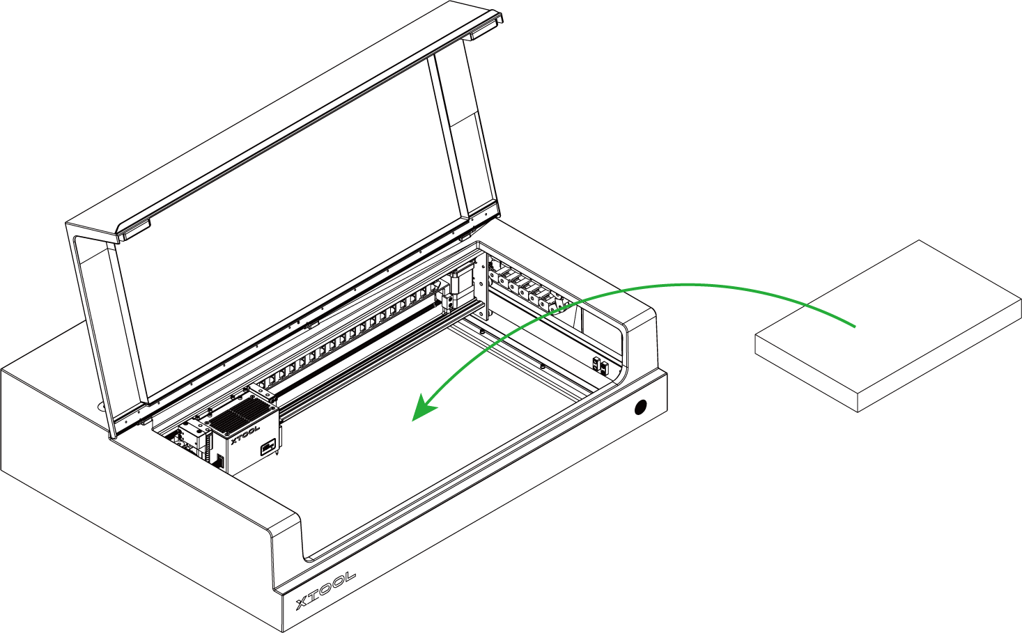
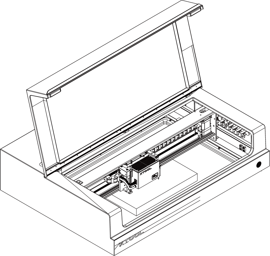
2. Place the material
Open the lid of xTool S1, and place the material to be processed on the baseplate.
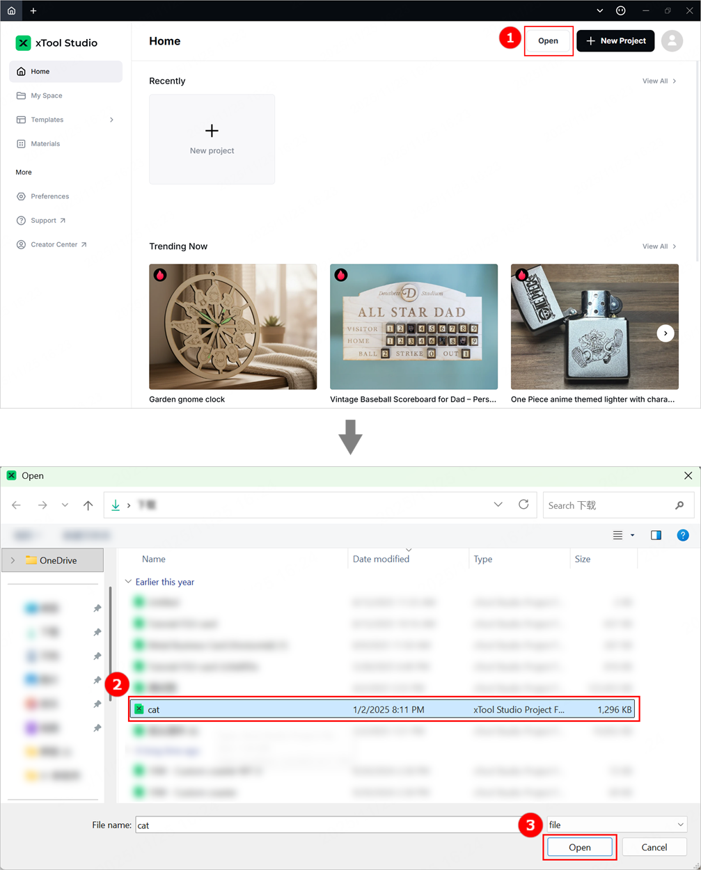
3. Open or create a project
You can open a project to start processing or create a new project. If you create a new project, you need to design patterns and set parameters from scratch.
- Open a project
On the home screen of xTool Studio, click Open. In the pop-up window, select the desired file and click Open.
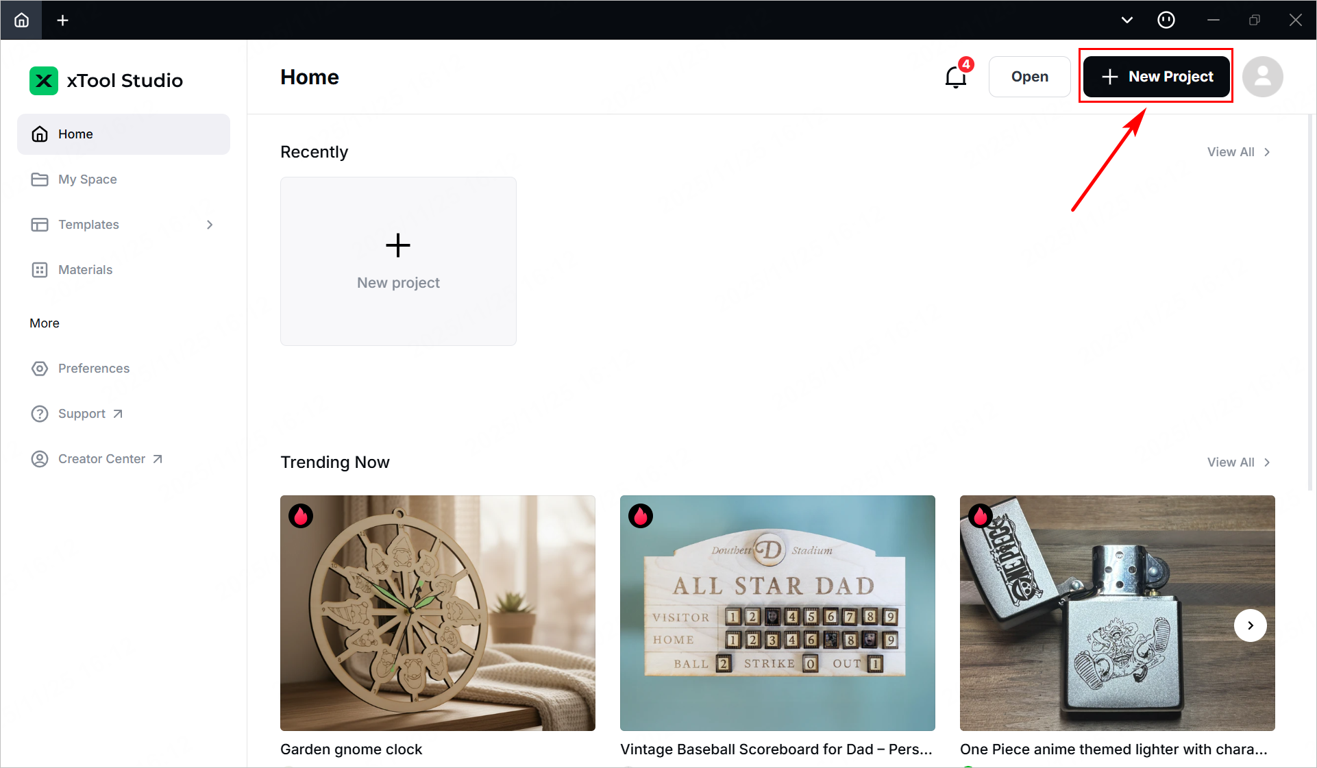
- Create a new project
On the home screen of xTool Studio, click + New Project.
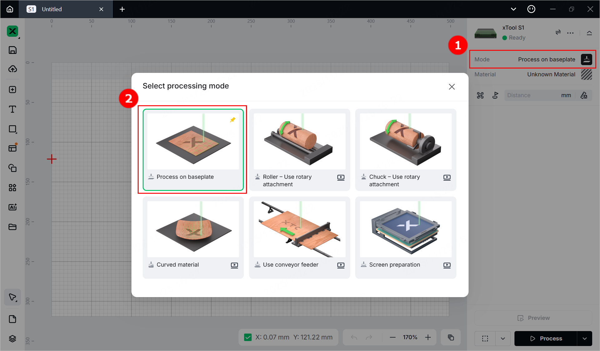
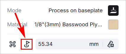
4. Select the processing mode and material
(1) In the right pane of the page, click the name of the current processing mode, and then select Process on baseplate.
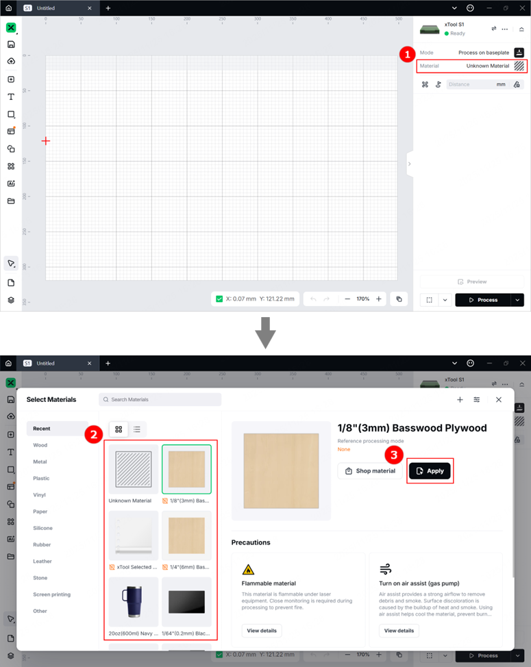
(2) Click Unknown Material, select the desired material, and click Apply.
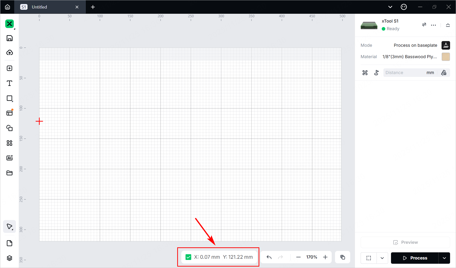
(3) Turn on or off Laser module position based on your need at the bottom of the page.
5. Set the laser focus
xTool S1 has a distance sensor, which can measure the distance between the laser module and the material surface. You can also manually measure and calculate the distance between the laser module and the material surface, and input the obtained values into the software.
During processing, xTool S1 will perform auto-focusing based on the Distance parameter.
- Auto measure
(1) Move the laser module over the material. Ensure that the locating spot falls on the surface of the material.
(2) In the right pane of the page, click the Auto-measure icon. xTool S1 will automatically measure the distance from the laser module to the material surface.
- Manual measure
(1) Use a ruler to measure the distance from the surface of the material to the top of the laser module.
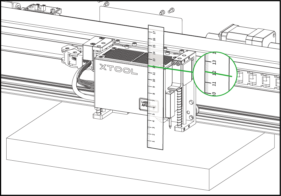
(2) Subtract 100 mm (3.937 inches) from the measured value from step (1), and input the calculated value as Distance in the right pane.
6. Mark the target processing area on the canvas
(1) Click  in the right pane.
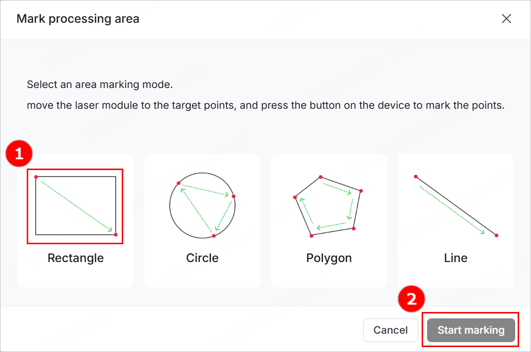
(2) In the pop-up window, select a marking mode based on the shape of the target processing area, and click Start marking.
(Here the Rectangle mode is used as an example.)
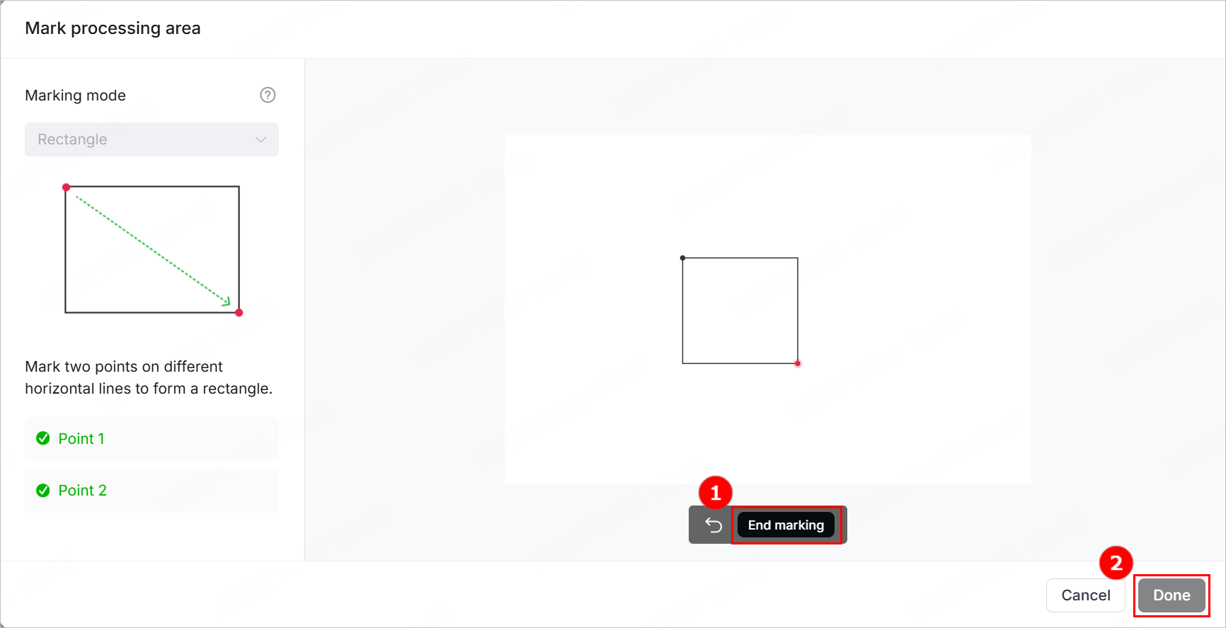
(3) Manually move the laser module to make the red cross fall at a vertex of the target processing area, and press the button on the device to record the position. Then, repeat the same steps to record the other required vertex(es) of the target processing area.
(4) Click End marking > Done, and then the target processing area will be marked out on the canvas.
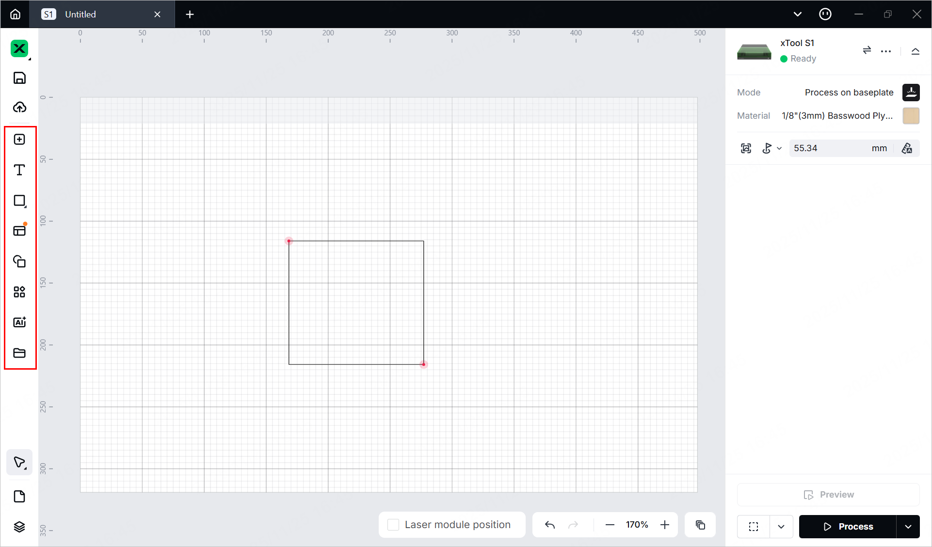
7. Design objects for processing
Note: The target processing area is marked out by a black perimeter as a rectangle. You can design objects within this area.
(1) Use the tools to the left side of the canvas to create objects. You can import images, insert shapes, enter text, or draw vector graphics.
Note: xTool Studio supports importing the following image formats: SVG, DXF, JPG, JPEG, PNG, BMP, etc.
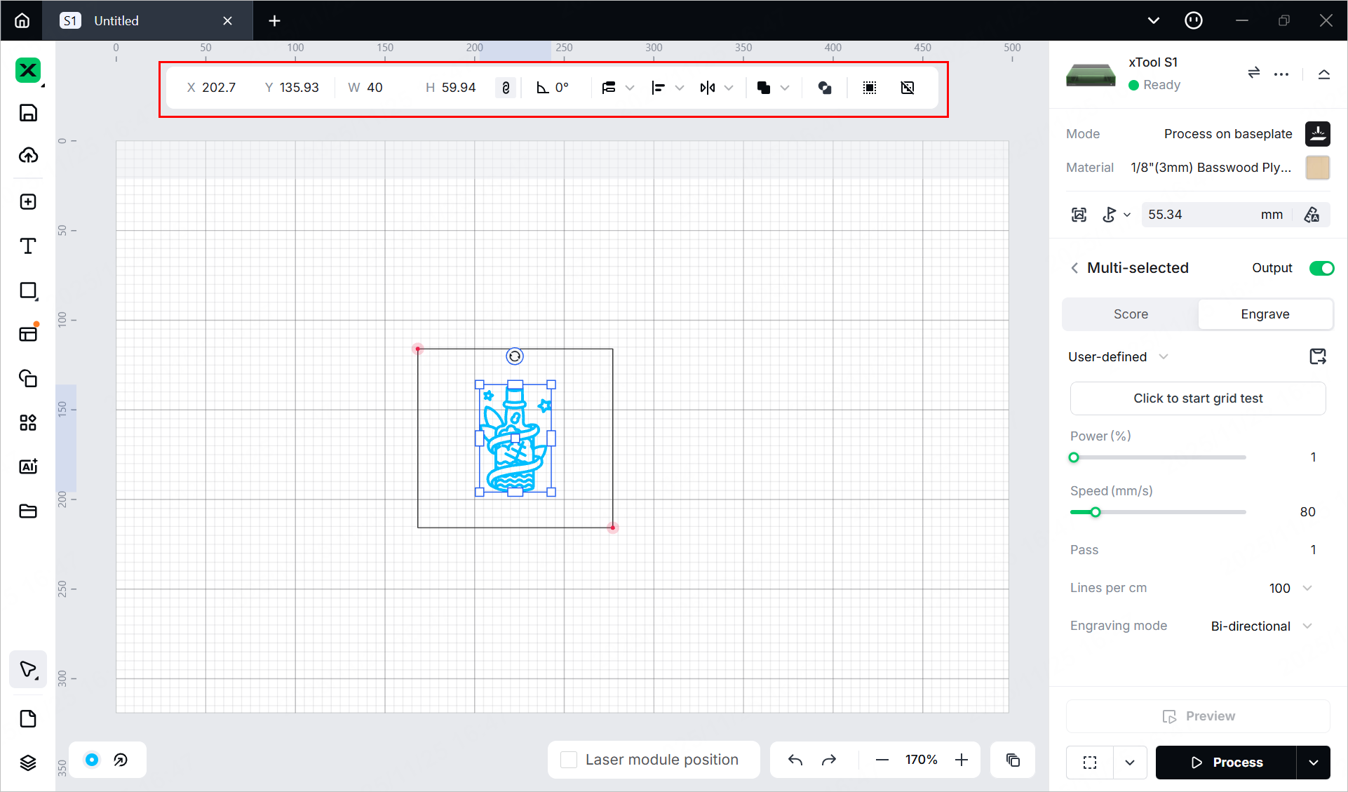
(2) Select the objects to further edit them using the tools above the canvas.
8. Set parameters for processing
Select objects on the canvas and set parameters for them in the right pane.
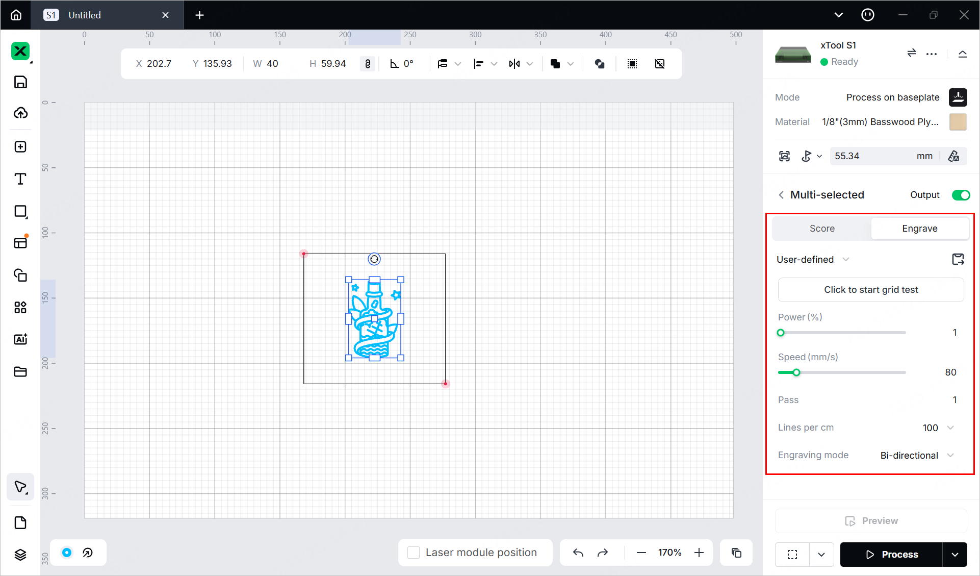
You need to set parameters for every object. A missed object may fail to be processed.
The parameters that can be set for bitmap objects and vector objects are different. You can select multiple objects of the same type and set parameters for them at once.
For more information on parameter settings, see atomm.com/easyset.
9. Preview the processing area and set processing path
You can preview the processing area on the material by framing. Framing means laser dots walk along the border of the processing objects on the material. Take the following steps to start framing.
(1) Click  in the bottom-right corner of the software and set parameters for framing.
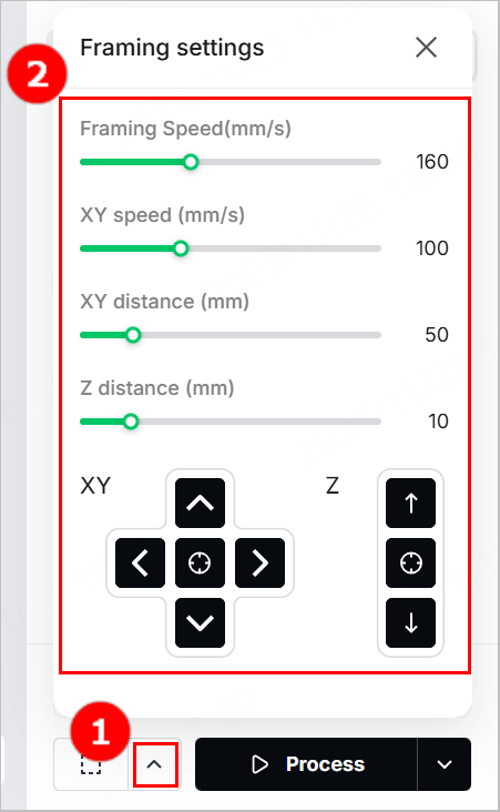
XY speed (mm/s): The moving speed of the laser module in X and Y directions.
XY distance (mm): The moving distance of the laser module with each tap on an XY arrow button.
Z distance (mm): The moving distance of the laser module with each tap on a Z arrow button.
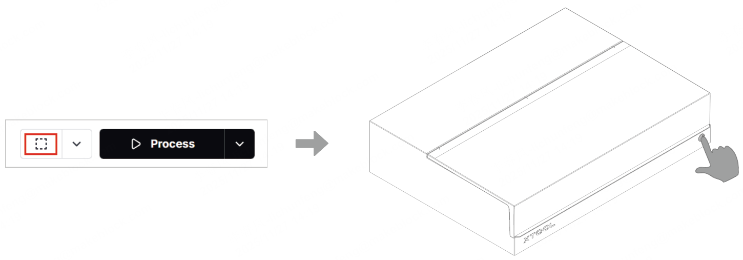
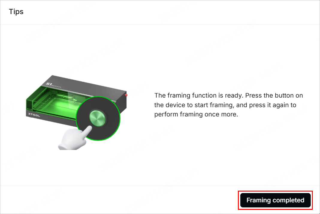
(2) Close the lid of xTool S1, click the framing button in the software, and then press the button on xTool S1 to start framing. The laser spot will move along the boundary of the processing pattern on the material.
(3) After the framing is complete, click Framing completed in the software. If the area is not ideal, you can adjust the material position or adjust the element positions in the software, and then preview the processing area again.
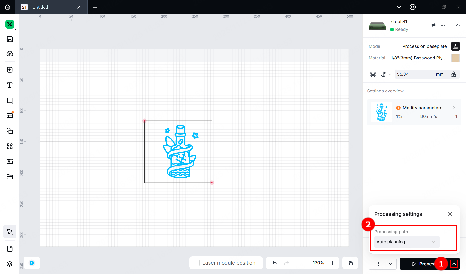
(4) Click  in the bottom-right corner and set processing path for processing.
10. Start processing
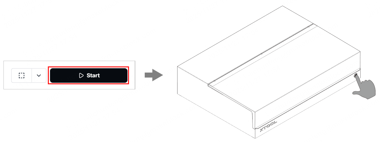
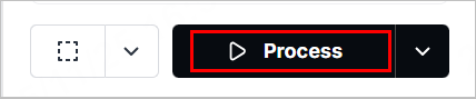
(1) In the bottom-right corner of the software, click Process.
(2) Click View path preview and  to preview the processing path.
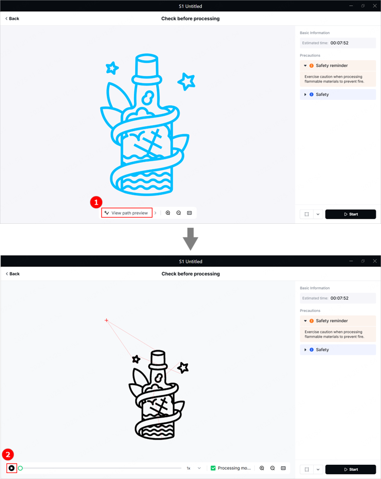
(3) In the bottom-right corner of the software, click Start. Then, press the button of xTool S1 to start processing.