1. Test Environment Setup
1.1 Preparation Before Inner Engraving
Detailed Step Description:
STEP1:
When performing inner engraving, the inner engraving lens must be installed. The inner engraving lens ensures better precision and overall quality of 3D inner engraving results.
STEP2:
Before replacing the inner engraving lens, the device must be powered off. Installing or removing the inner engraving lens while the device is powered on is strictly prohibited.
STEP3:
In the Select Processing Mode menu, choose Inner Engraving to access the Inner Engraving Settings. After selecting Inner Engraving, you can click on the corresponding material to apply the recommended parameter settings.
1.2 Inner Engraving Settings
STEP1:
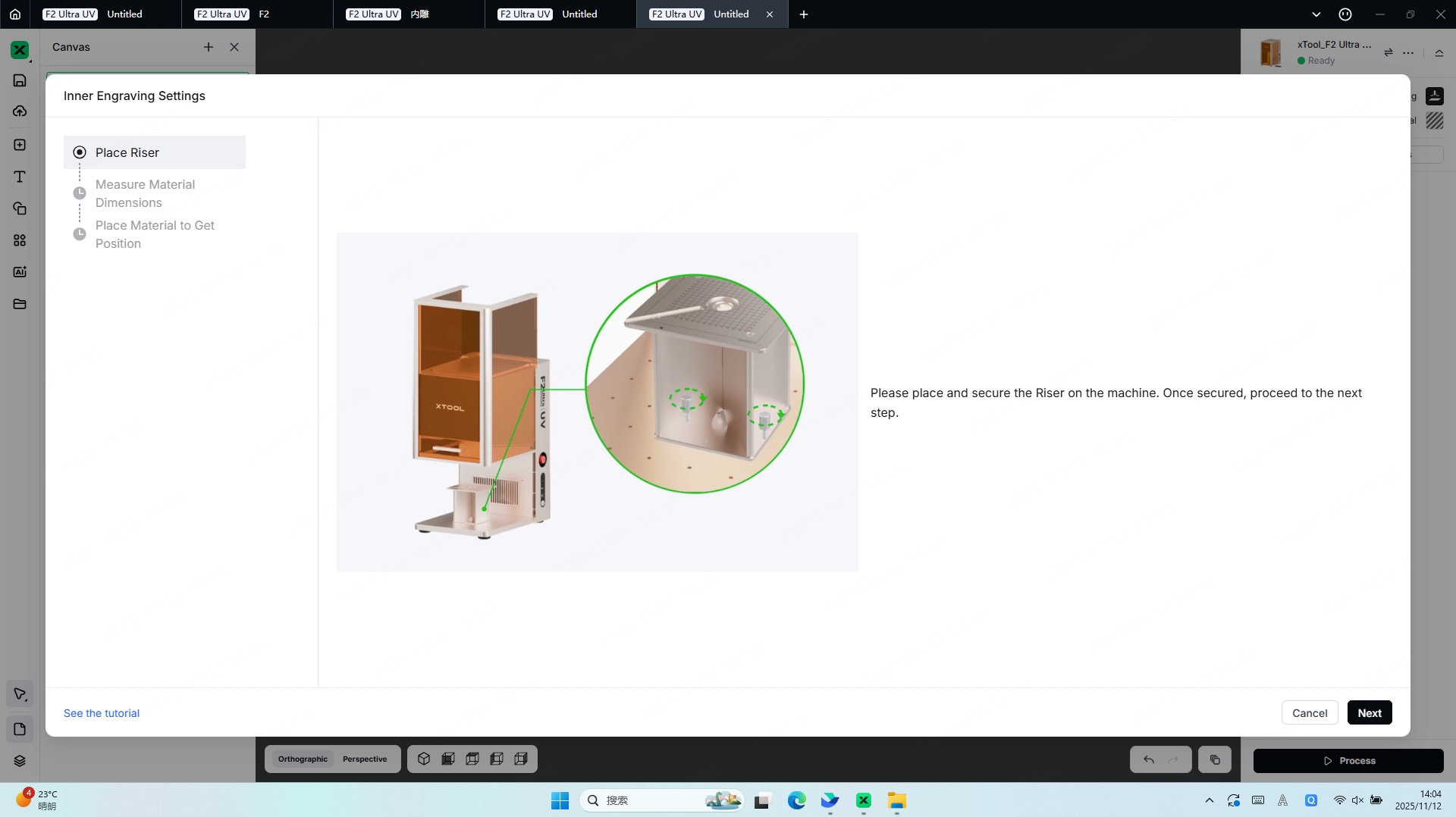
Install the riser to facilitate subsequent Inner Engraving Work Area Calibration and material placement.
STEP2:
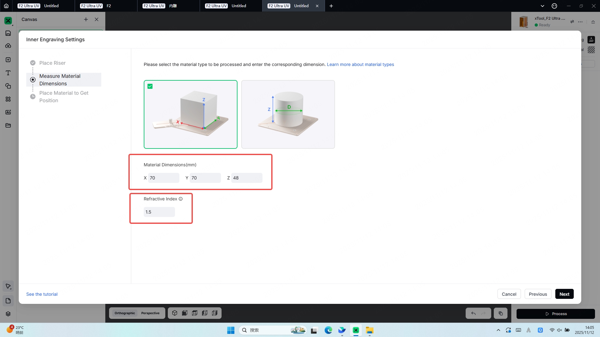
Measure Material Dimensions,Whenever possible, select materials with regular geometric shapes. Choose the corresponding model shape based on the form of the material you intend to engrave.
Square/Rectangular Materials:X, Y values: Represent the length and width of the material,Z value: Represents the height (thickness) of the material.
Cylindrical Materials:Z value: Represents the height of the cylinder,D value: Represents the diameter of the cylindrical material.
The refractive index must be entered, and its value can be obtained either from the material specifications of the glass or by performing a measurement yourself.
STEP3:
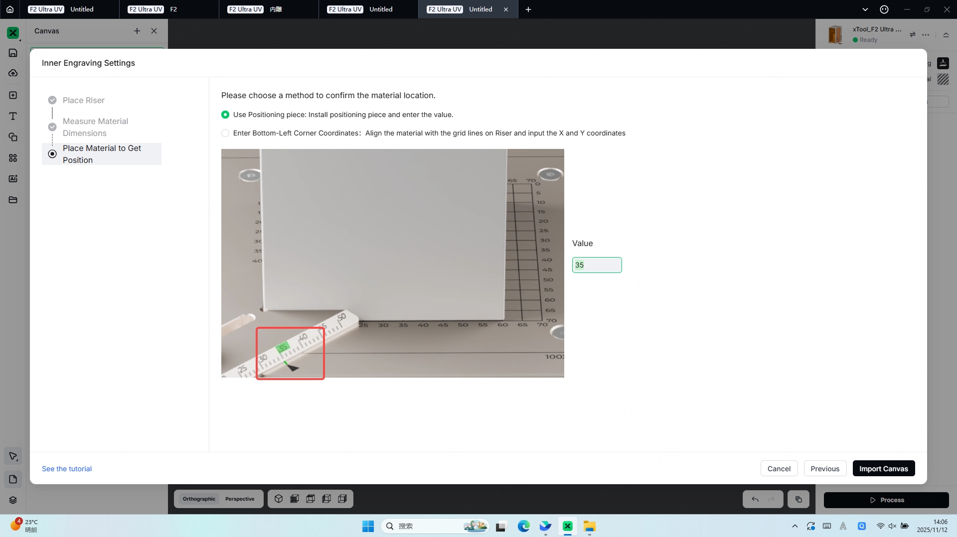
The purpose of Confirm the Material Location is to allow the software to generate a 3D model based on the material dimensions provided in the previous step. This 3D model helps verify both the size of your glass material and its position inside the device, ensuring accurate placement assistance for subsequent engraving operations.
It is recommended to use the Positioning Piece. The positioning piece allows for faster and more precise material positioning and also provides a certain level of stabilization during the engraving process.
Enter the value indicated by the arrow on the positioning piece into the corresponding Value field. The software will use this value to calculate the starting position of the material’s 3D model.
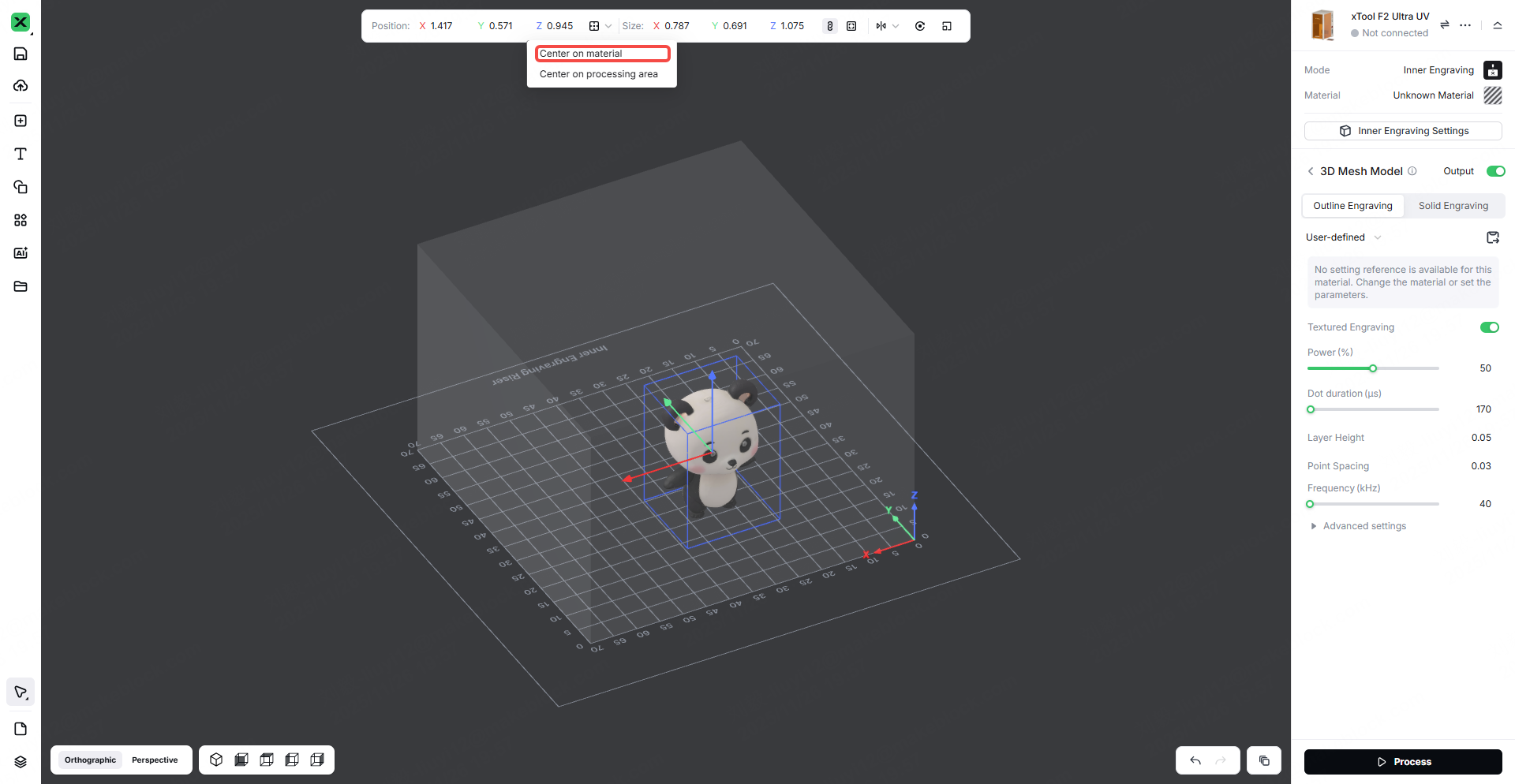
1.3 Position the 3D Engraving Model
3D engraving models can be created using external software or generated directly in Studio through AIMAKE.
After importing the 3D model into the workspace, you must scale it so that it fits entirely within the material’s outer contour model. Any portion of the 3D model that extends beyond the material boundary cannot be engraved or displayed by the laser.
Note: After selecting the material, you can click Center on Material to automatically move the 3D model to the center of your glass material’s working area.
2. Device Calibration
2.1 Open Inner Engraving Work Area Calibration
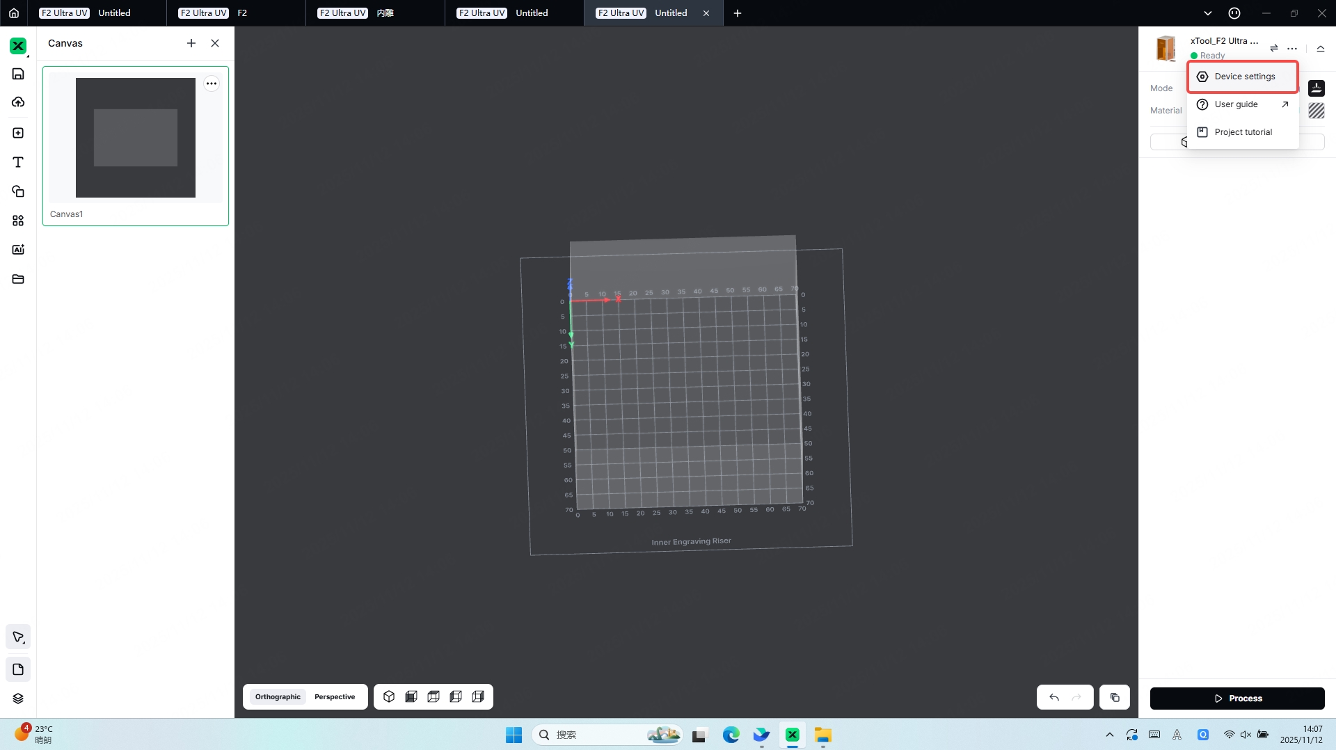
Open Inner Engraving Work Area Calibration:
Ensure Processing Accuracy:Calibrate the laser focal position, optical path perpendicularity, and motion-axis positioning accuracy to ensure that the cutting/engraving dimensions and positions match the design precisely.
Protect the Device and Materials:Prevent laser path deviation or incorrect focal points that may concentrate laser energy on unintended areas. Proper calibration reduces wear on optical components (such as lenses and mirrors) and minimizes material waste.
Avoid Safety Risks:Calibrate the laser beam path and safety interlock mechanisms to ensure the laser does not deviate from the intended processing area, preventing accidental burns to operators or damage to surrounding equipment.
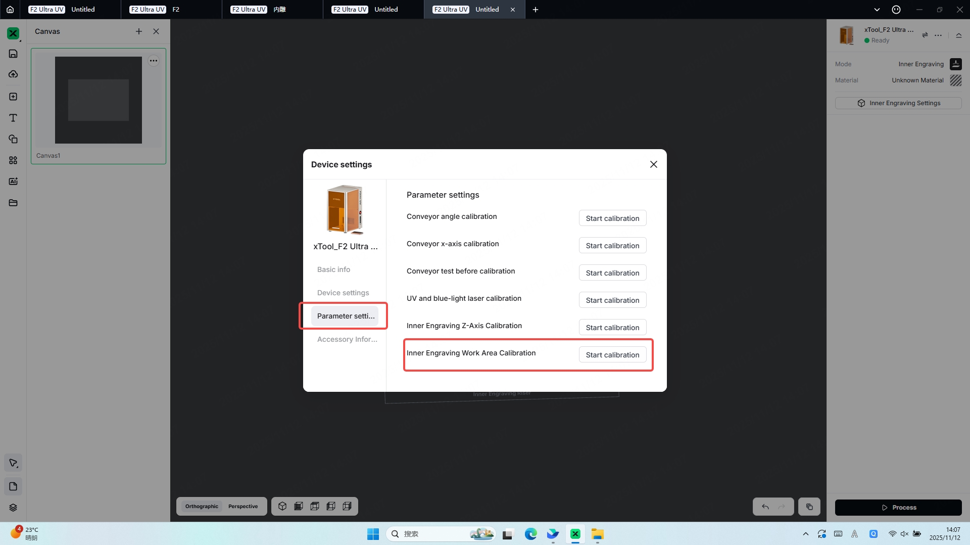
2.2 Inner Engraving Work Area Calibration
STEP1:
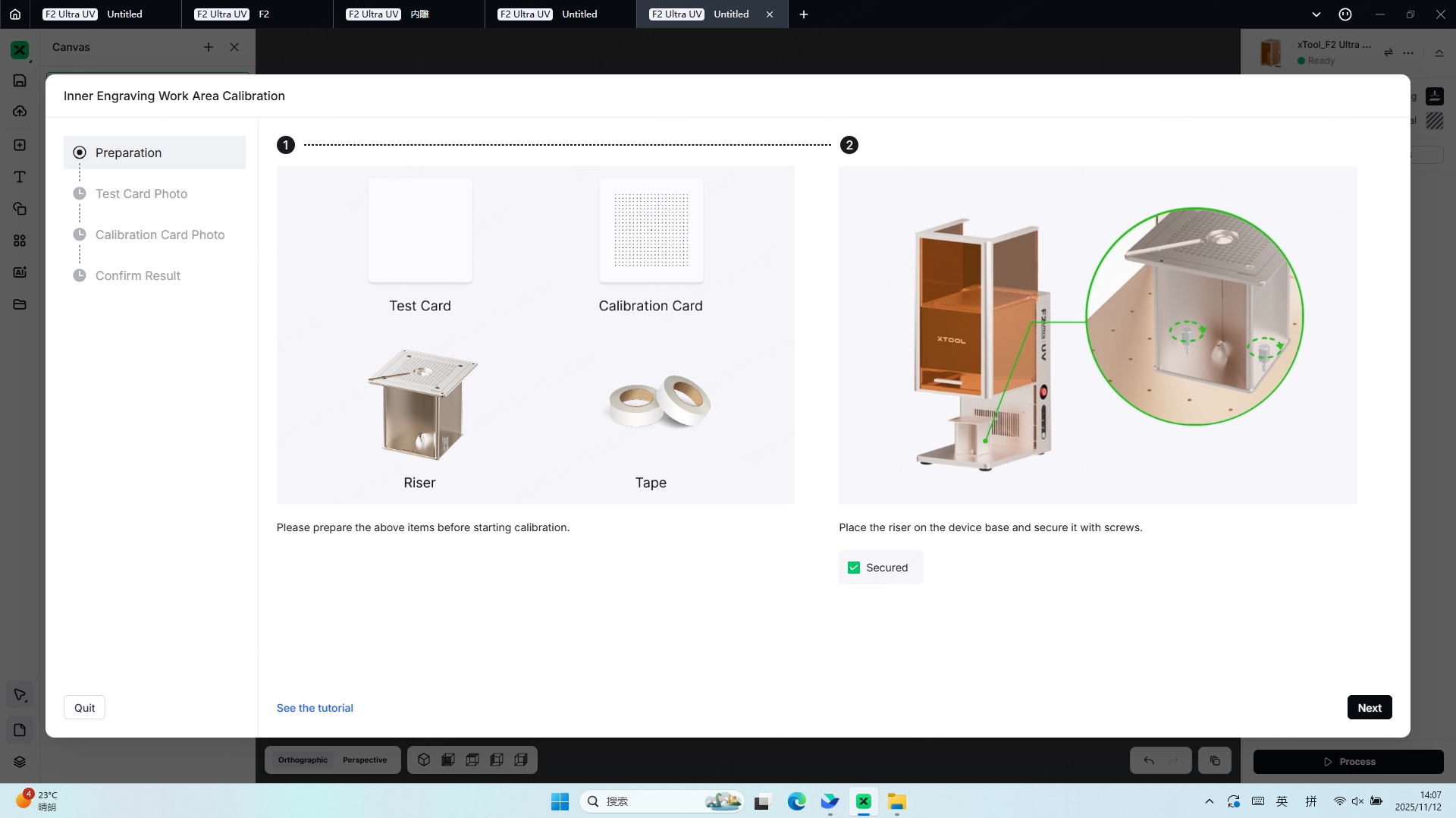
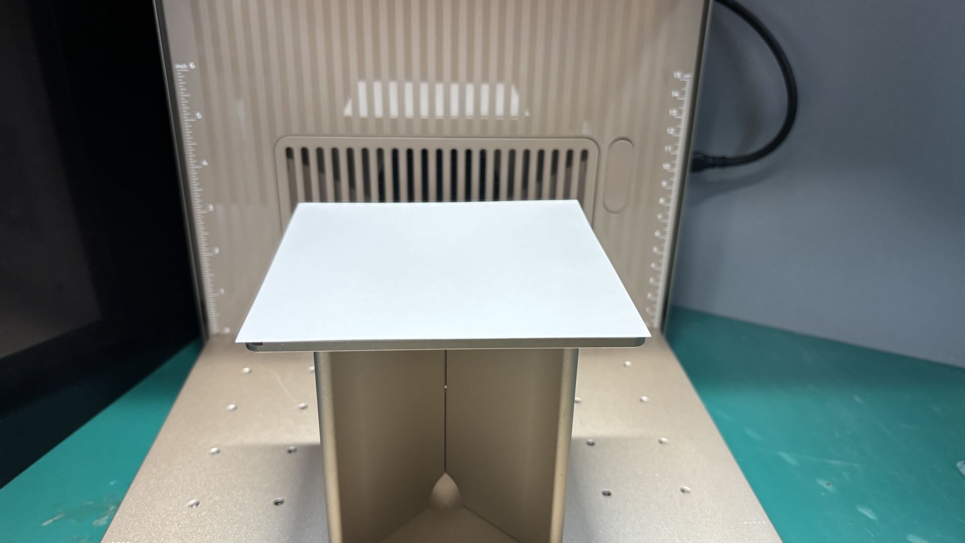
First, install the riser. If a positioning piece is attached to the riser, remove the positioning piece before proceeding.
Place the blank test card on top of the riser. If the test card is not lying flat, use masking tape or similar tools to secure it in place.
Once the test card is properly positioned, you may begin the engraving process.
STEP2:
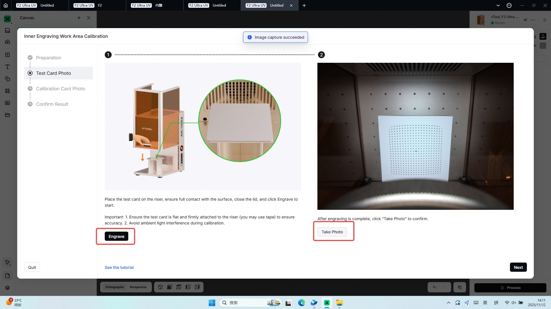
After the test card is properly positioned, you can proceed with Take Photo to view the placement in the software.
Since the engraving process requires a certain amount of time, please keep the device’s protective cover closed during engraving and pay attention to odor protection and ventilation.
STEP3:
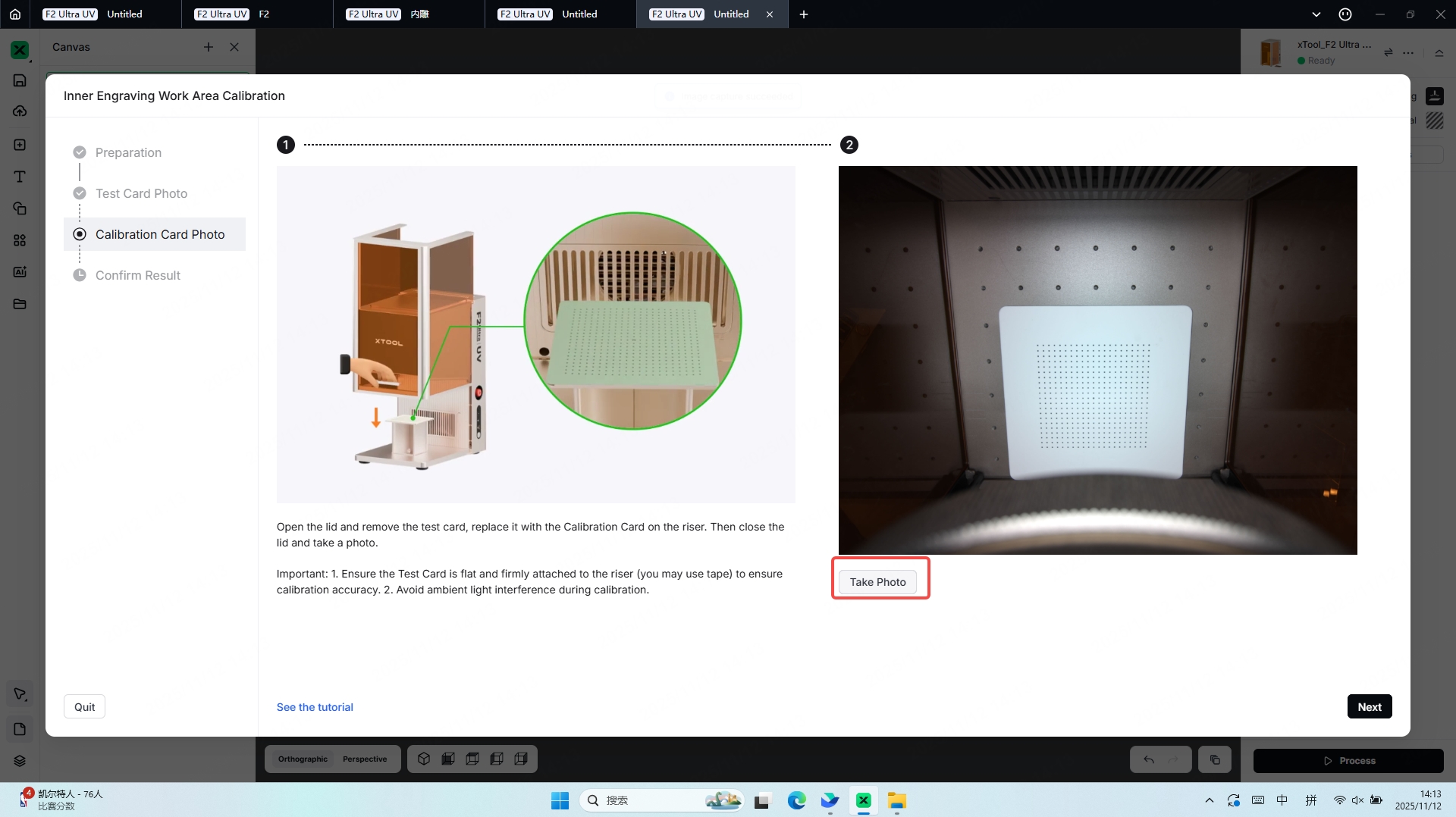
Perform the Take Photo operation on the test card after the engraving is completed, then proceed to the next step.
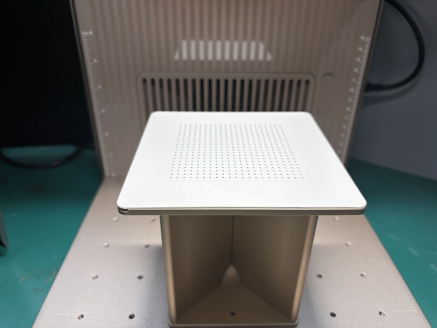
Following the on-screen instructions, remove the test card and replace it with the Calibration Card.
Once the Calibration Card is properly secured, perform the Take Photo operation again.
STEP4:
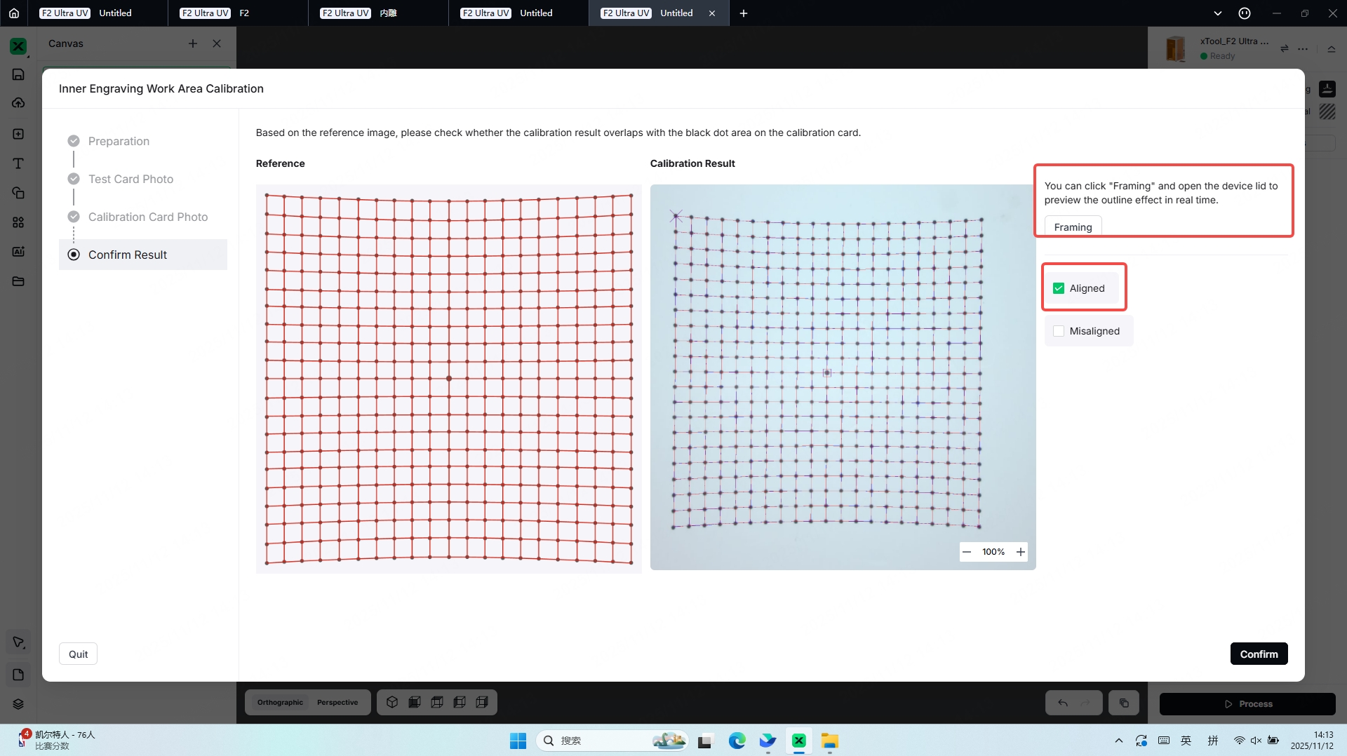
After performing the Take Photo operation on the Calibration Card, proceed to the next step,Based on the reference image, check whether the calibration result overlaps with the black dot area on the Calibration Card.
Select the corresponding option in the software according to the displayed result:
If the result is Aligned, you may proceed to the next step.
If the result is Misaligned, follow the troubleshooting instructions to resolve the issue.
3. 3D Model Engraving Method
3.1 3D Model File Formats and Their Recommended Engraving Methods
Scanning Engraving | Dotting Engraving | Textured Engraving | Inner Engraving | 3D Photo | Solid Engraving | |
|---|---|---|---|---|---|---|
STL | √ | √ | √ | |||
GLB | √ | √ | √ | |||
OBJ | √ | √ | √ | |||
jpg/png | √ | √ |
3.2 Scanning Engraving
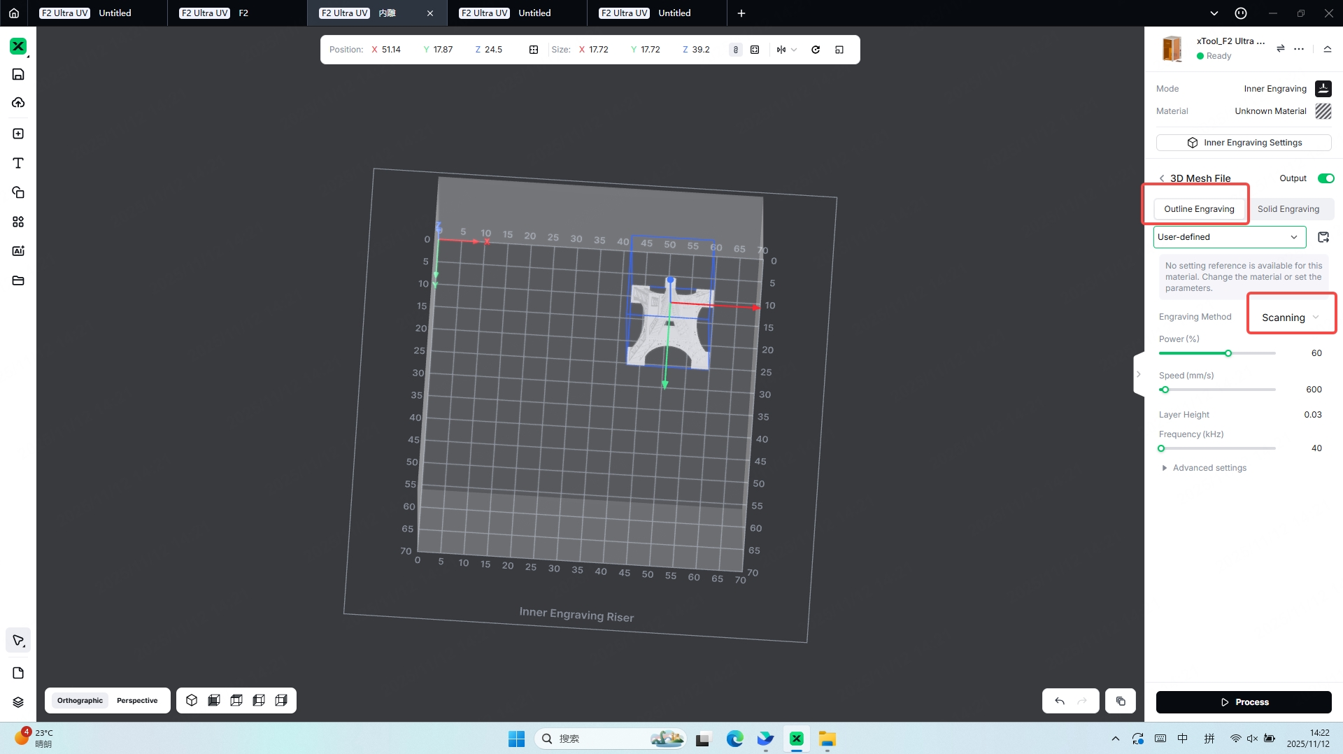
Characteristics:
In the glass inner-engraving laser mode, the primary advantage of Scanning is its ability to deliver energy continuously along the engraving path. Compared with Dotting and other modes, this continuous scanning allows the laser to generate a more uniform internal stress distribution and smoother micro-fractures within the glass. As a result, the engraved model presents higher refinement and stronger three-dimensional depth without the grainy dot-matrix appearance, displaying naturally flowing lines that reproduce complex details and gradient effects with precision. At the same time, Scanning reduces the risk of internal chipping, improves overall transparency, and ensures visual consistency throughout the finished piece, making it especially suitable for fine ornaments, intricate designs, and other inner-engraving scenarios that demand high precision and premium visual quality.
The Scanning mode processes faster than the Dotting mode and requires less time to complete the engraving.
3.3 Dotting Engraving
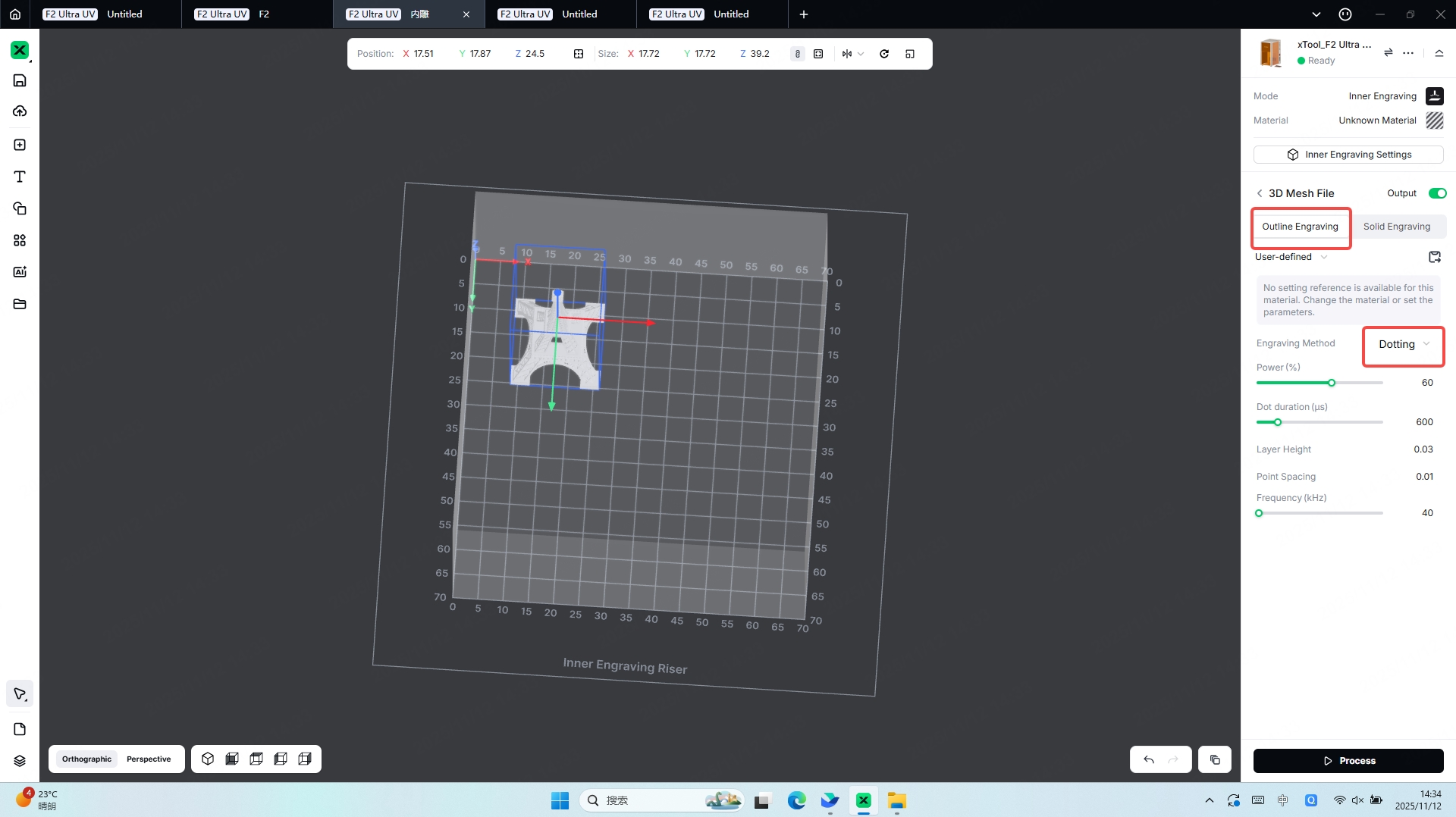
Characteristics:
In the glass inner-engraving laser mode, the core characteristic of Dotting is its use of densely distributed, discrete laser pulses to create individual micro-explosion points inside the glass, which then combine to form the final pattern. This approach offers stronger adaptability to complex graphics because it does not require continuous path planning and can efficiently fill large areas. Since the energy is concentrated at individual points, Dotting produces a clearer sense of depth and a distinct granular texture, while also placing relatively lower demands on equipment precision. Additionally, it reduces the likelihood of internal stress concentration within the glass that may occur during continuous-path Scanning, making Dotting a stable and flexible option for various inner-engraving scenarios.
3.4 Textured Engraving
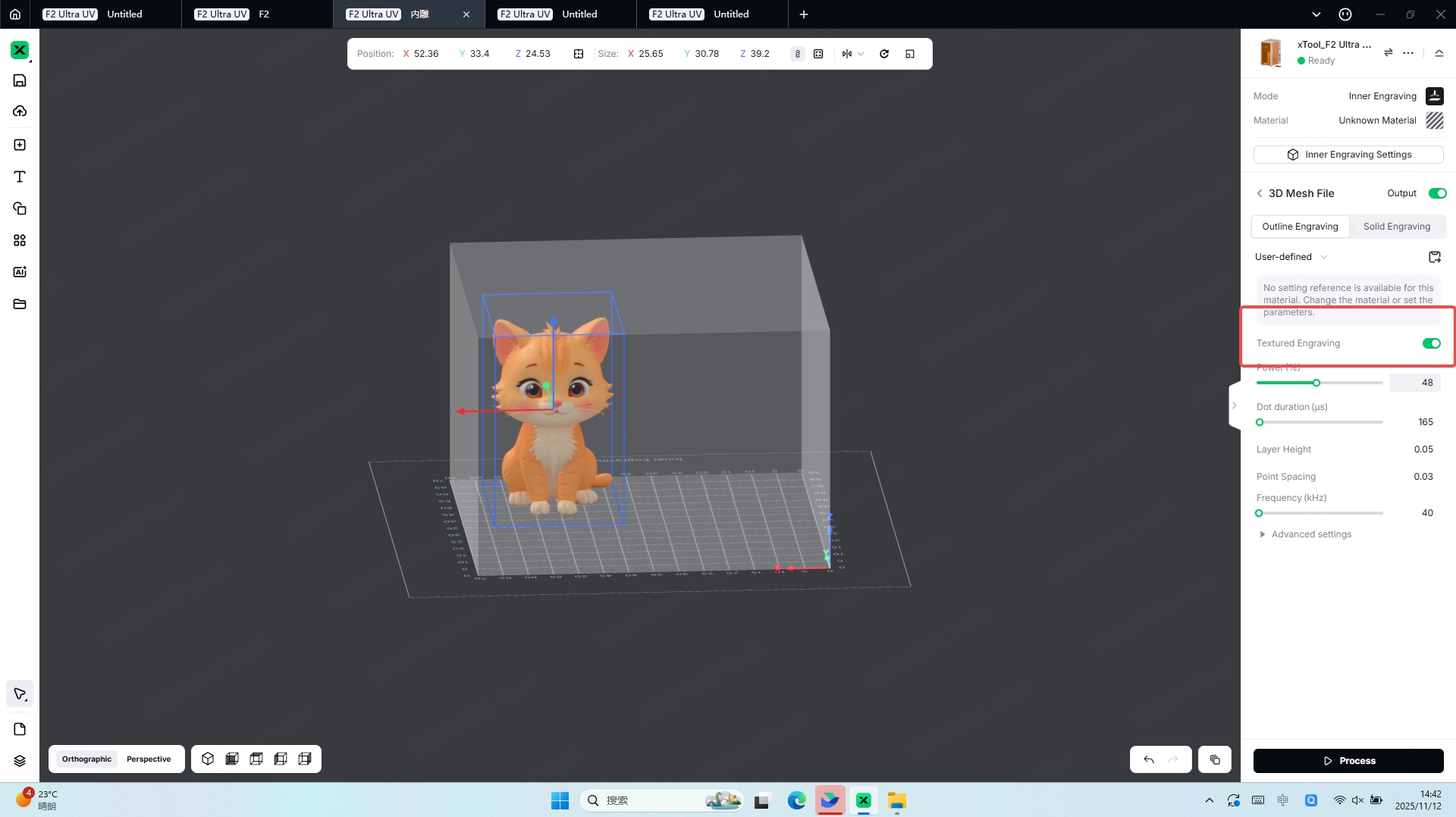
Characteristics:
Texturedengraving refers to the process of engraving the surface textures of a model inside the glass, making the model more realistic and vivid.
When engraving a 3D model with textures, it is not recommended to disable the Textured Engraving option. Processing with Textured Engraving enabled helps make the model more realistic and vivid.
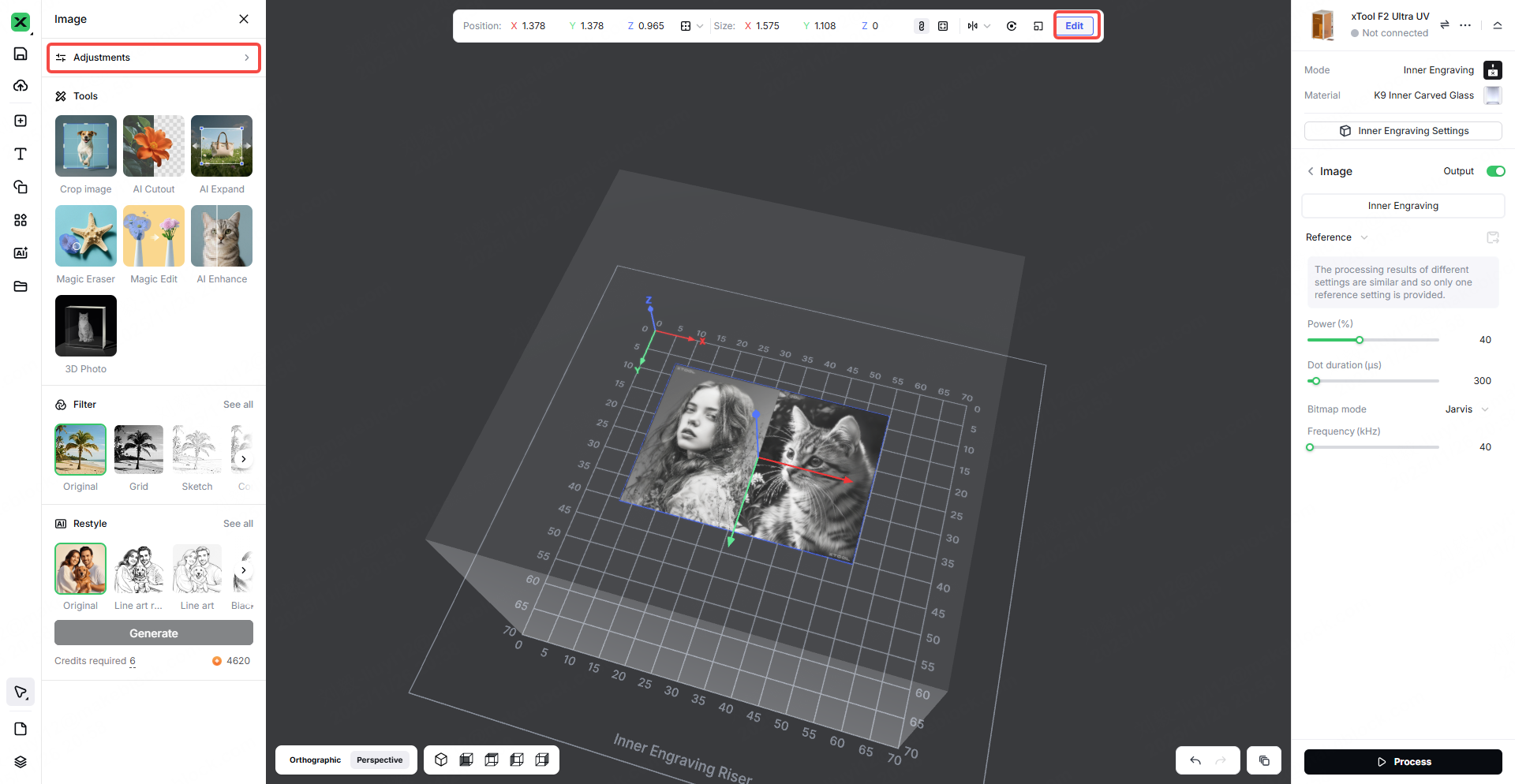
3.4 Inner Engraving
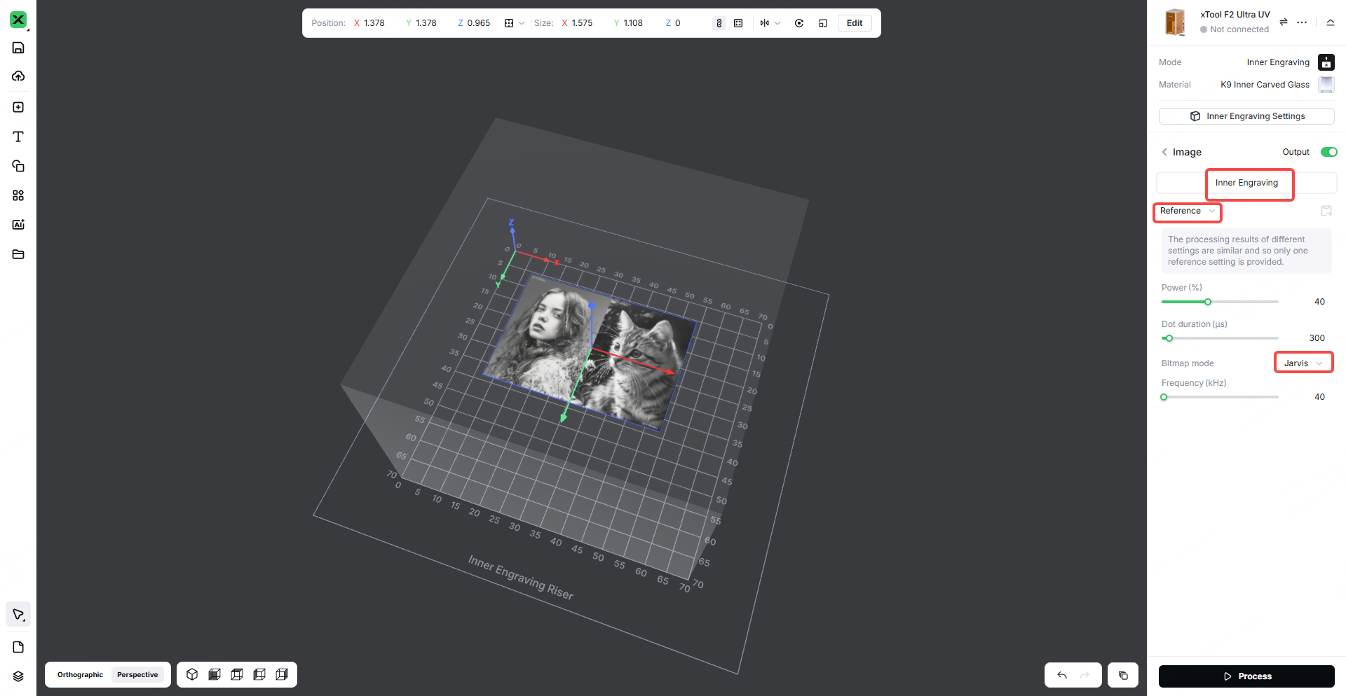
After importing a flat photo into the software, you can click Center on Material to place the photo at the center of the material model. When performing Inner Engraving with a flat image, positioning the image on the horizontal plane provides the best engraving results.
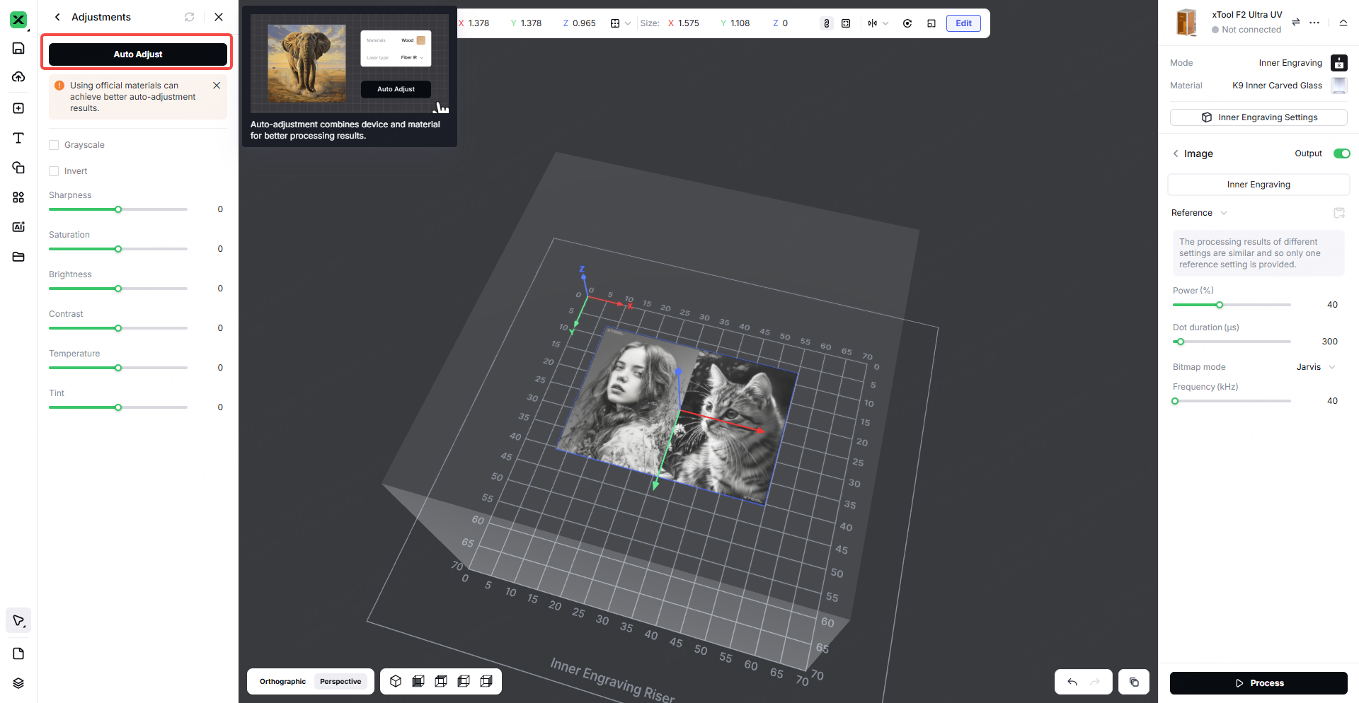
Auto Adjust – Step 1
Auto Adjust – Step 2
The image imported into the software can be processed with Auto Adjust, and the auto-adjustment feature combines device and material parameters to achieve better engraving results.
3.6 3D Photo
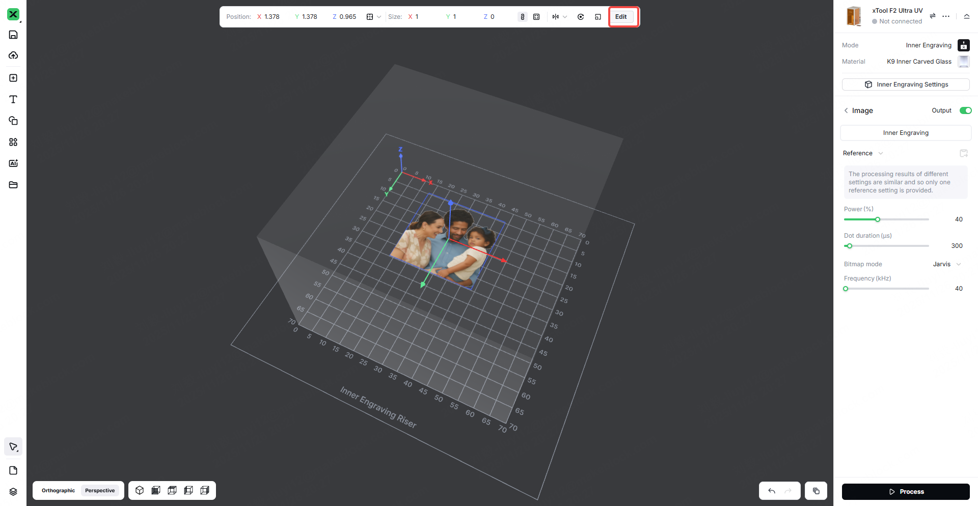
Flat Image to 3D Model – Step 1
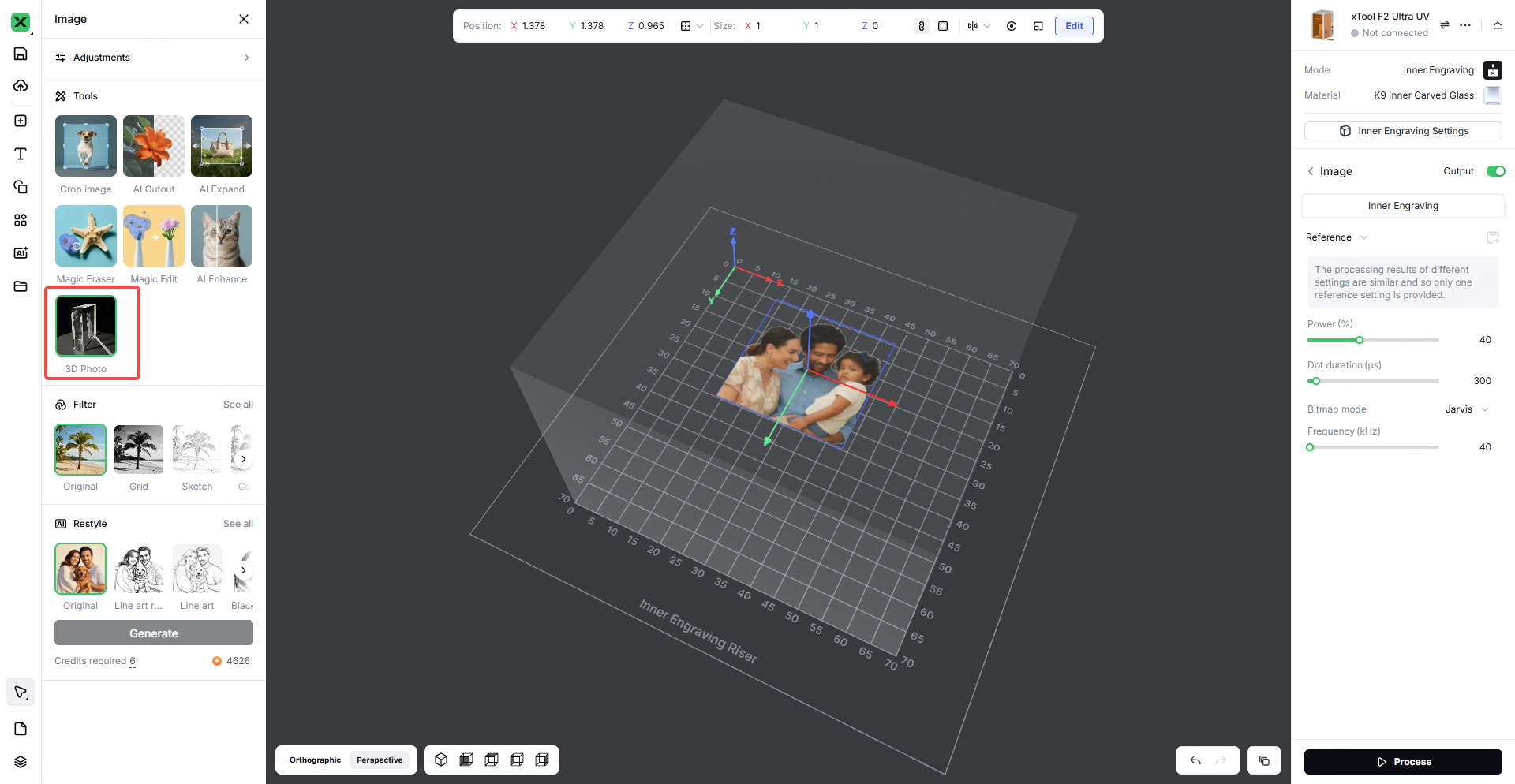
Flat Image to 3D Model – Step 2
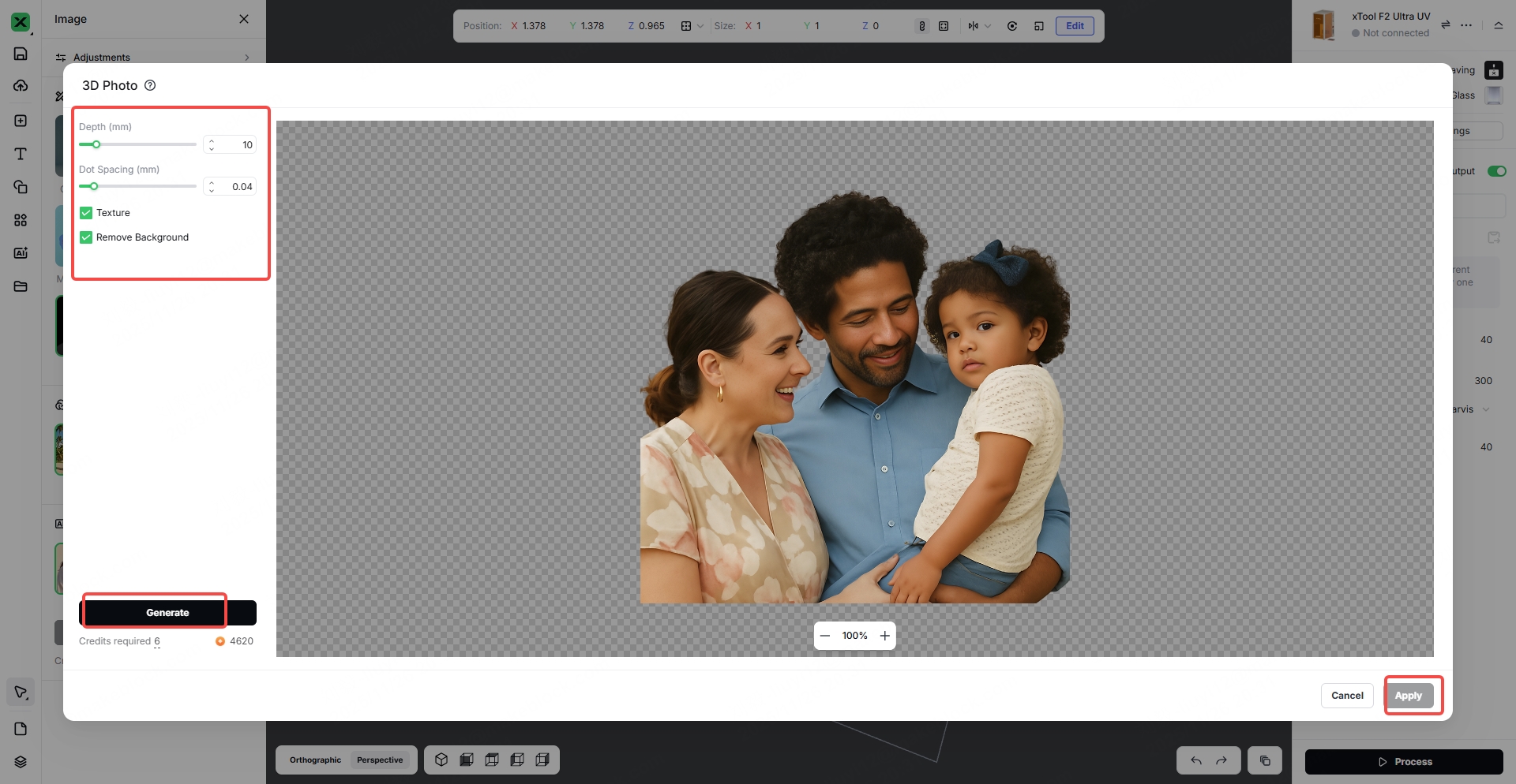
Flat Image to 3D Model – Step 3
Convert your image into a realistic 3D relief model. Adjust the depth to control the level of dimensionality.
3.7 Solid Engraving
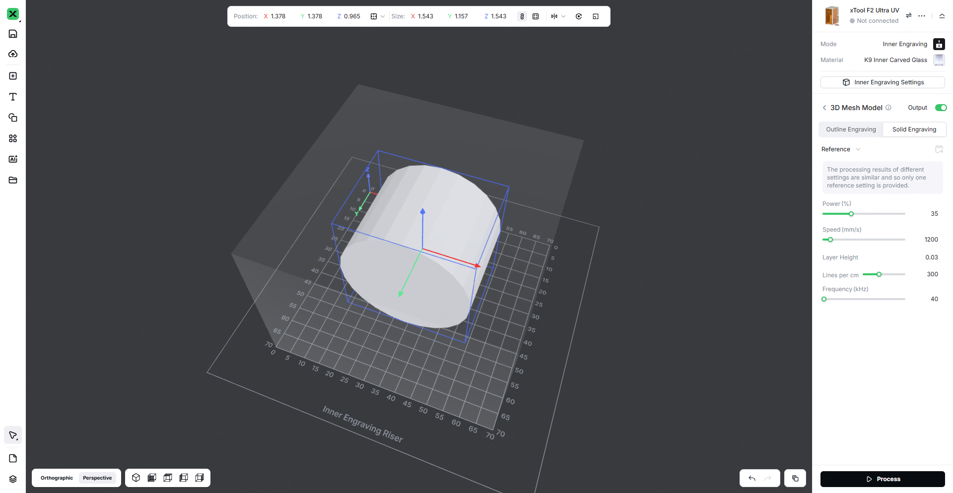
Characteristics:
In the glass inner-engraving laser mode, the fill engraving method allows the designated area to be fully filled along a complete path, achieving a solid fill effect that accurately reproduces the graphic contours and delivers a uniform texture. This makes it suitable for large-area designs and high-precision engraving applications requiring consistent and detailed filling.
4. FAQ
4.1 No Engraving Effect
Surface contamination on the material:
Dust, oil, and other particles on the glass surface can directly block UV laser penetration, preventing the laser energy from effectively reaching the interior of the glass. Because UV lasers have relatively weak penetration and are easily absorbed or scattered by surface contaminants, these impurities may also carbonize under laser exposure, adhering to the surface and further hindering energy transmission, ultimately making it impossible to form internal micro-fractures for engraving.
Surface fingerprints or liquid residues:
Oils, sweat, or other liquids left on the glass create an optical interface on the surface and alter the refraction path of the UV laser. This causes the focal point to deviate from the intended engraving depth, preventing the energy from concentrating inside the glass at the designated location. In addition, liquids absorb heat and may produce micro-bubbles that disrupt energy distribution, resulting in a complete loss of engraving effect.
Abnormal laser engraving parameters:
Parameter mismatch is the primary cause—such as focal deviation (UV lasers have an extremely narrow focal range), excessively high scanning speed (insufficient interaction time to induce internal stress changes in the glass), or improper pulse frequency (too high causing inadequate energy accumulation, too low causing dispersed energy). These issues prevent the laser from reaching the energy threshold required for internal engraving, making it impossible to create micro-explosion points or micro-fractures.
Low laser power:
UV lasers inherently have limited energy density, and if the power does not reach the critical threshold for internal glass engraving, the laser cannot overcome the molecular bonding forces inside the material. As a result, it cannot generate the microstructural changes needed for internal engraving, and even with correct parameters, only faint marks—or no engraving effect at all—will appear.
4.2 Blurry or Unclear Engraving Result
If the 3D model is not proportionally adapted and adjusted:
Directly engraving a raw 3D model without scaling it according to the glass thickness, the effective internal engraving depth, and the UV laser focal range may cause parts of the model to fall outside the usable engraving region (either too deep or too shallow), or cause key details to be inaccurately rendered due to disproportionate scaling. In addition, when the model size does not match the laser engraving travel, edge details may be compressed or overlapped, ultimately resulting in a blurred or hazy appearance.
Excessive laser power:
UV laser energy is highly concentrated, and when the power exceeds the appropriate threshold, too many micro-explosion points may form inside the glass. These points can overlap or spread into each other, destroying the clarity of boundaries and fine details. Excessive energy may also cause localized stress concentration and irregular internal fracturing, producing a cloudy or diffused effect in the engraved area. In severe cases, this leads to detail loss and blurred contours.
Improper point spacing and layer height settings:
If the point spacing is too large, the laser impact points become sparse, leaving detail gaps, visible graininess, and blank areas that produce an overall blurry effect. If the point spacing is too small, energy overlap causes adjacent details to fuse together. Incorrect layer height settings—too high resulting in harsh transitions between layers, too low leading to overly dense layering and energy accumulation—will disrupt the 3D model’s depth and detail gradation, ultimately causing blurred contours, poor detail definition, and failure to faithfully reproduce the original structure of the model.
4.3 Internal Cracks Inside the Material
Excessive laser power:
When the UV laser power exceeds the appropriate threshold for glass inner engraving, the localized energy inside the material becomes excessively concentrated, instantly generating a large number of high-temperature, high-pressure micro-explosions. This disrupts the stability of the internal molecular structure and not only forms the intended micro-fractures for engraving but also produces irregular, extended cracks. These cracks may interlace and spread, damaging the integrity of the engraved contours and, in severe cases, causing large-scale internal fragmentation of the material, making it impossible to achieve a proper engraving result.
Overly slow engraving speed:
If the engraving speed is too slow, the laser remains on the same region of the glass for an extended period, causing continuous energy accumulation beyond what the material can withstand. This intensifies the micro-explosion effect, enlarging originally controlled micro-fractures and allowing them to propagate outward, creating unwanted internal cracks. Excessive energy also results in rough and jagged crack edges, degrading engraving detail accuracy and negatively affecting the visual quality of the final piece.
Services & Help
Learn & Education

Copyright © 2025 xTool All Rights Reserved.