Issue description
Issue in the software
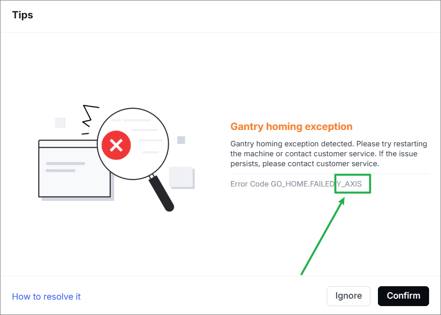
The software prompts "Gantry homing exception" and the error code indicates "GO_HOME.FAILED.Y_AXIS".
Issue 1 in the device
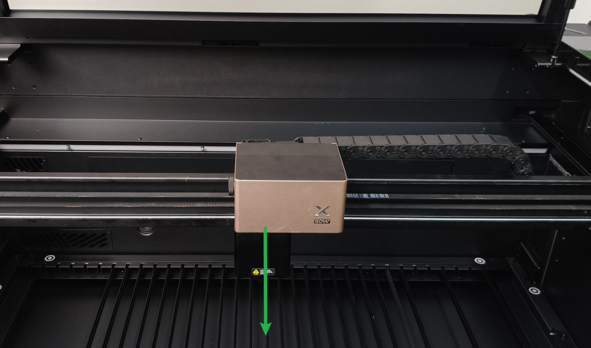
Move the laser module to the middle of the device.
When the device is powered on, the laser module moves slowly toward the lid for a short distance before stopping.
Issue 2 in the device
Move the laser module to the middle of the device.
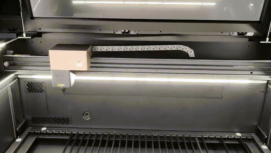
When the device is powered on, the laser module moves backwards to its home position at normal speed. However, it will get stuck during the movement (typically at the final position), producing vibrations and noise.
Important notes
One motor is positioned on each side of the Y-axis, with two motors corresponding to two limit switches. The device functions properly only when both motors and limit switches operate correctly.
After moving the laser module to the center of the device, power on the device. Before the Y-axis has completed its reset, the indicators for both sides of the Y-axis limit switches should be off.
Possible causes
- The limit switch is dirty.
- There are foreign objects on the moving route of the gantry.
- The limit switch is faulty.
Troubleshooting procedures
⚠️ Safety First: Power off your device before performing the step.
1. Check the rear of the gantry
Check whether foreign objects are blocking the reset of the gantry on the back and the device's inside. If present, remove them.
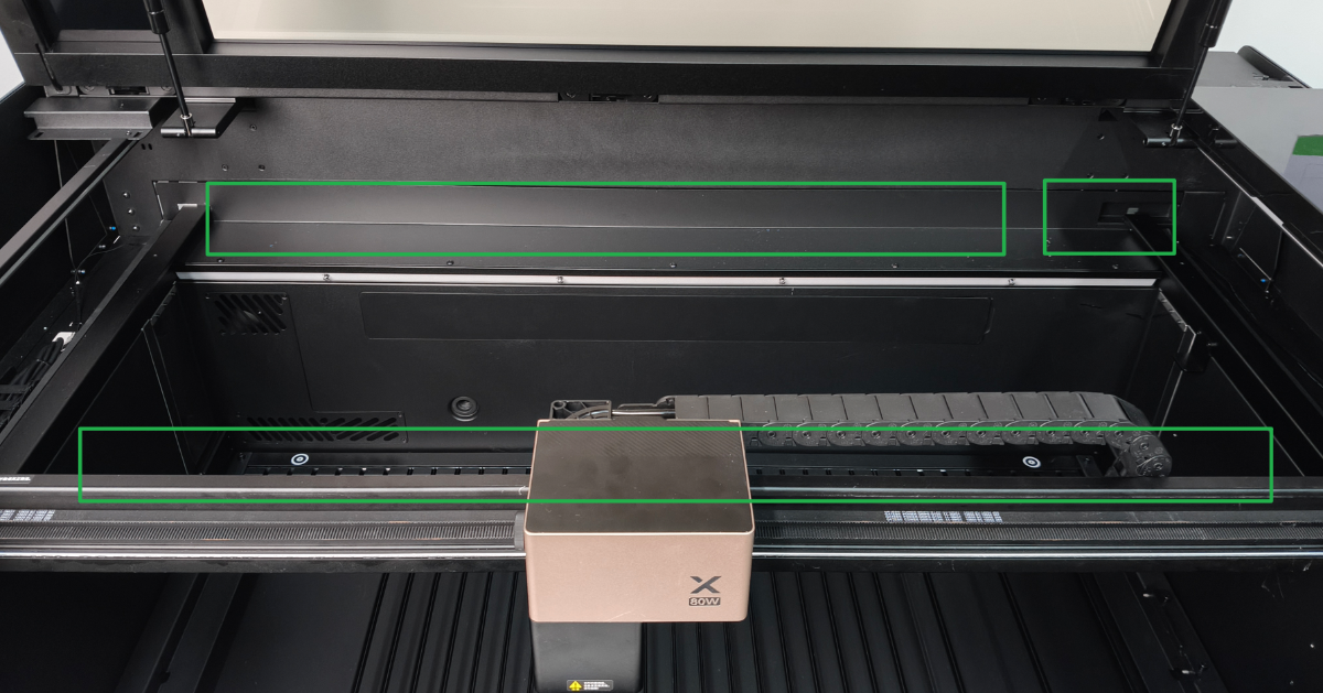
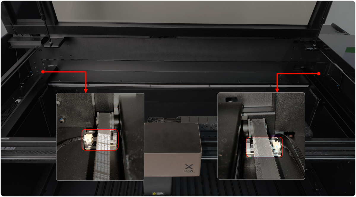
2. Check the limit switch
You can use your phone's camera and flash to observe the limit switch on the right, which is more helpful for observation.
- Check if the black probe of the limit switch is distorted or damaged. If yes, remove it to fix or replace a new one.
- If the connection cables of the limit switch are loose, please unplug and plug the cables. Then, restart xTool P3.

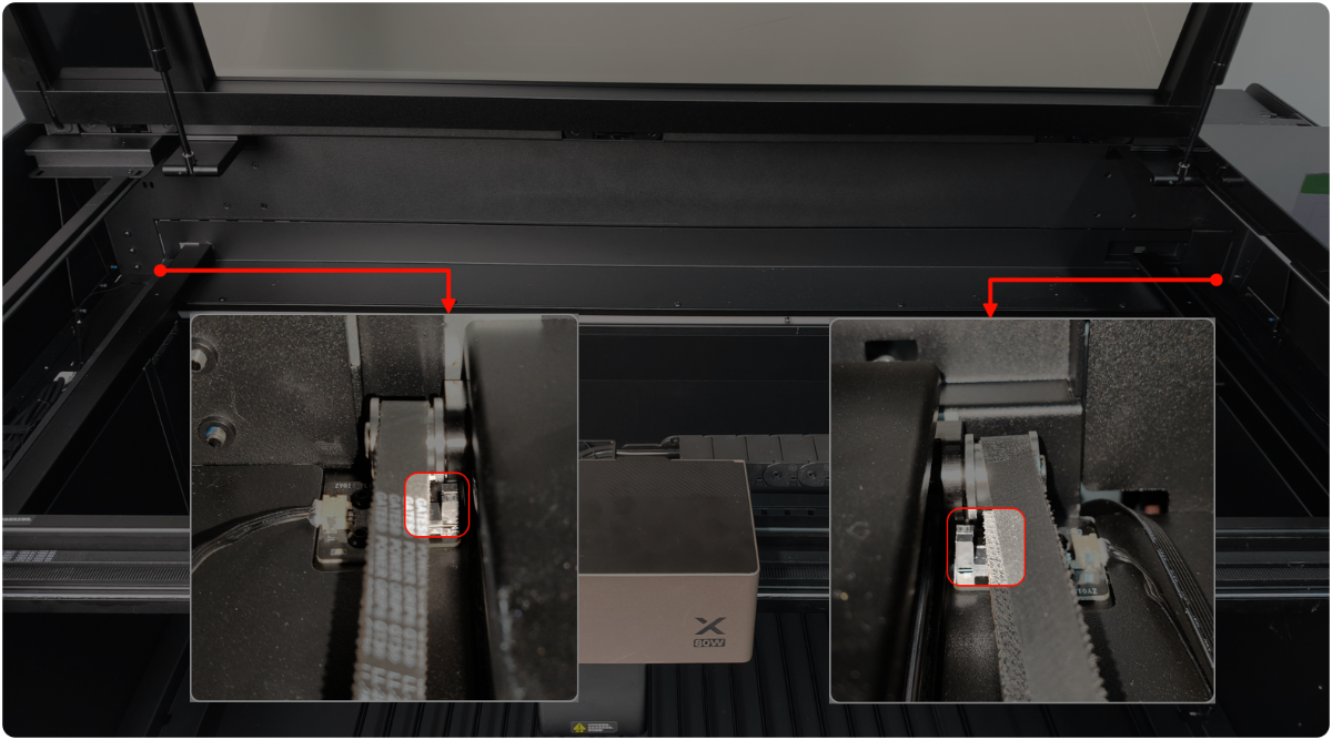
3. Check the limit switch area
You can use your phone's camera and flash to observe the limit switch on the right, which is more helpful for observation.
(1) Power off the device.
(2) Check whether there are foreign objects in the middle and nearby areas of the black probe of the limit switch on the left and right sides of the gantry. If there are some, please clean them.
4. Test the limit switch
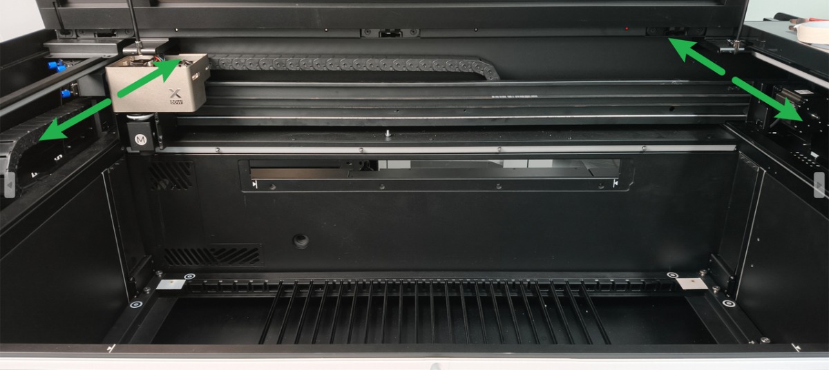
(1) Move the gantry to the origin position and make it parallel.
(2) Slide the gantry back and forth on both the left and right sides (you may hear a clicking sound from the motor if you force it, and this operation will not damage the machine for a short time, you don't need to worry).
(3) Observe whether the corresponding limit switch indicator changes according to the operation.
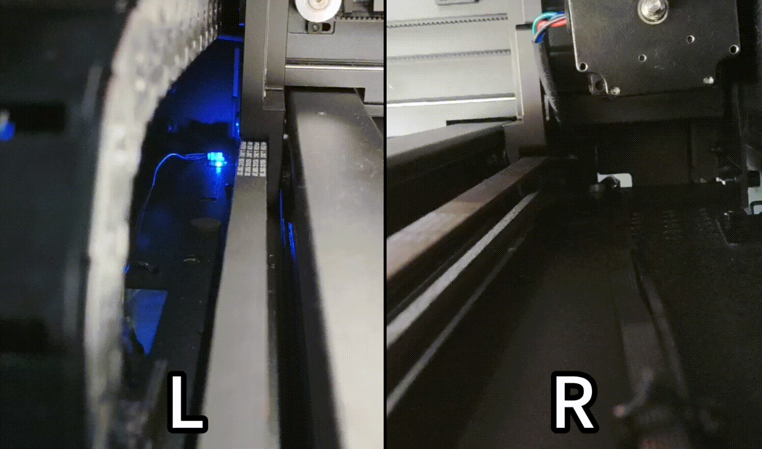
- If the indicator will not change, follow Step 5 to check the connection cables.
- If the indicator changes due to the operation, check for other issues.
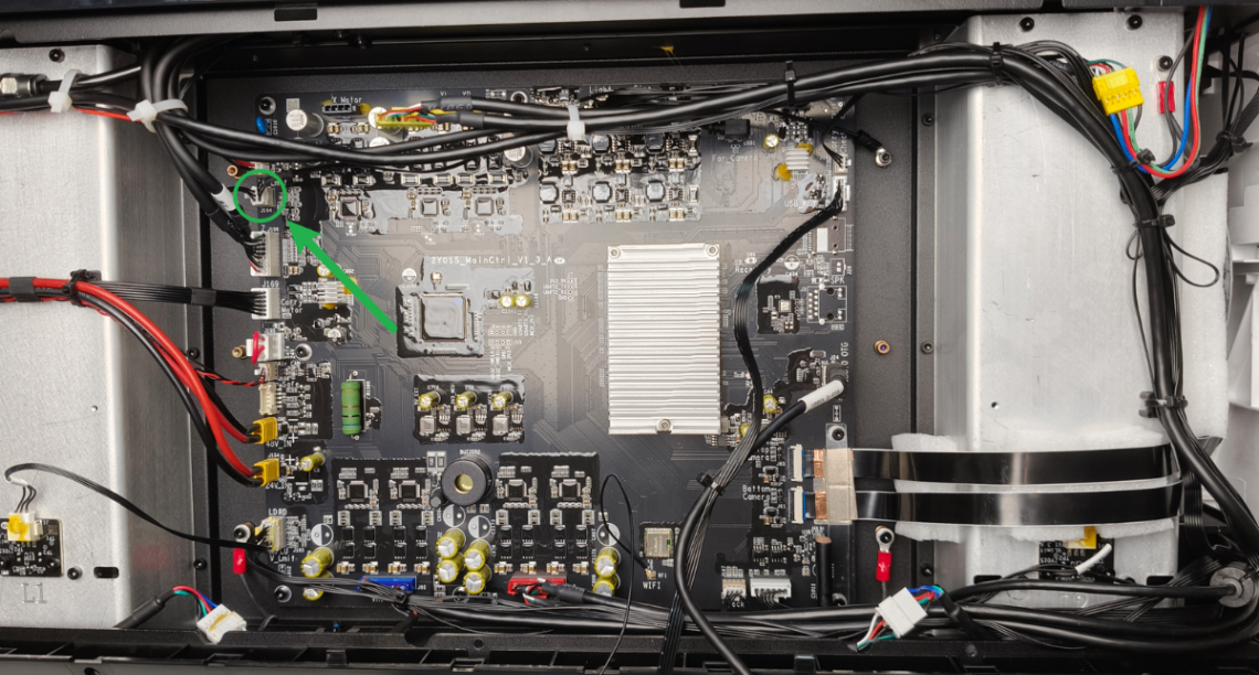
5. Check the connection cables of the limit switch on the main control board's end
If a faulty limit switch is detected during the previous limit test, please follow the steps to inspect the limit switch connection cables:
(1) Disconnect xTool P3 from a power supply.
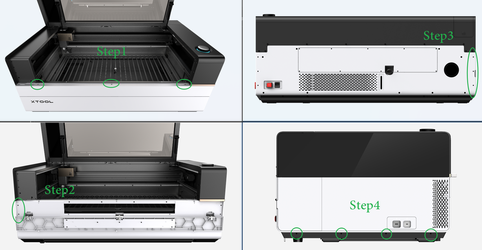
(2) Remove the left plate as shown. And you can see the video tutorial Assemble & Disassemble the Casing of xTool P3.
(3) Check whether the connection cable on the Y-axis limit switch is loose, and unplug and plug it (as shown).
Still experiencing issues?
Should the issue persist after completing the preceding steps, submit a ticket via the "Submit a Ticket" button in the "Help Ticket" section below. The standard response time for xTool Customer Service is one business day.
For a prompt resolution, please include the following details:
- Issue description: A detailed explanation of the observed problem.
- Video evidence: Attach a video demonstrating the issue, where applicable.
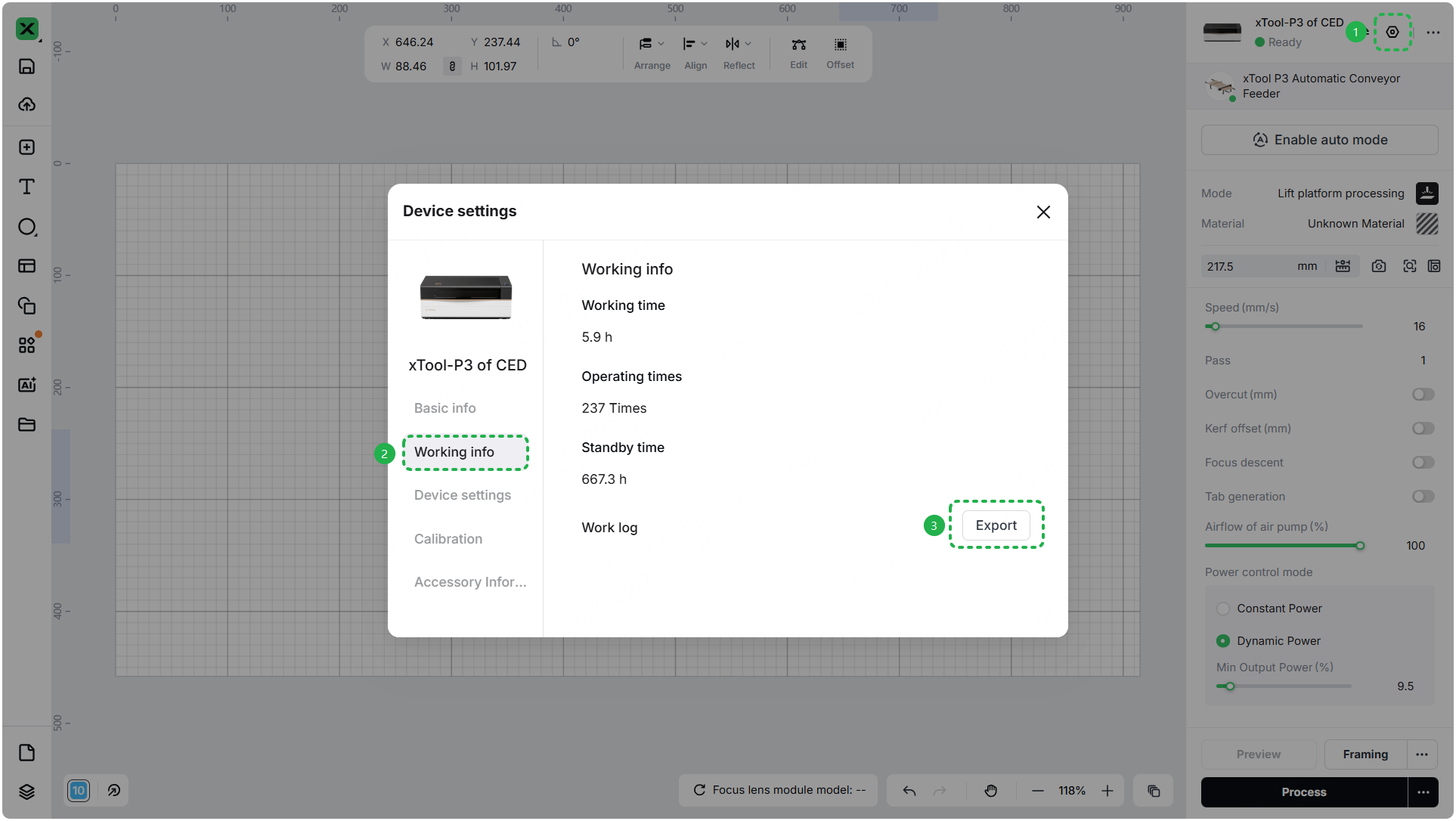
- Device information: Follow the steps to find the SN and export the work log.

- Troubleshooting performed: Any troubleshooting steps you have already attempted, along with their results.
This information is crucial for xTool technical support engineers to provide timely assistance.
Documentation feedback
Help improve this content by providing feedback. If this content did not meet your requirements, select "No" in the "Was this page helpful?" section below. Include specific details about what was unclear or missing in the pop-up suggestion box. Feedback submissions are reviewed by xTool technical writers to enhance future documentation.
Services & Help
Learn & Education

Copyright © 2025 xTool All Rights Reserved.