
Applicable scenario
The laser module has come off the guide rail due to improper operation or other unexpected reasons, and needs to be reinstalled on the guide rail.
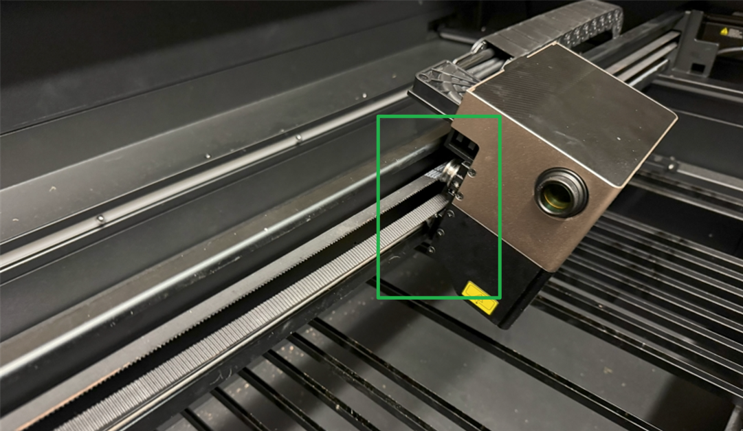
Issue description
Common causes of the laser module falling from the guide rails:
- Improper operation in the Auto measure, causing the laser module to collide with the material.
- Under unprotected conditions, the laser module may fall due to gravity (commonly occurring during transportation).
To prevent this issue from recurring, it is recommended that you pay attention to the following precautions.
Precautions on Auto-measure
- If you use Auto-measure, the transparent materials cannot be detected. Please exit Auto-measure and perform the manual measurement by any of the following methods:
- Measure the distance from the material surface to the air nozzle and subtract 4 mm, which is the measurement value to be entered in the software.
- Apply a full-coverage sheet over the transparent material. After using Auto-measure, manually subtract the thickness of the sheet, and then enter the value in the software.
- Apply a 10 cm × 10 cm white masking tape onto the transparent material. Ensure the measurement point is positioned on the masking tape during measurement. Remove the masking tape after completing the measurement.
- The high-refletive, black and matte, or red materials may affect the auto measurement. If the measurement fails or the result is a significant deviation, follow the methods for the transparent materials.
- For the thickness of a material that is more than 30 mm, check if the highest surface of the material is at least 5 mm lower than the air nozzle. If not, turn the knob to lower the lifting platform.
- Maximum height that can be measured (Auto mode): 180 mm
- Maximum height that can be measured (Manual mode): 220 mm
- Do not place the material close to or cover the origin and slat slots.
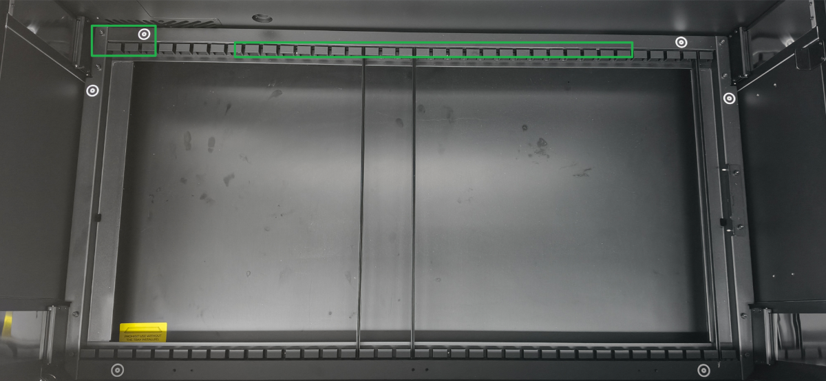
Precautions on transportation
- Pack the device as much as possible in its original standard, secure the gantry and baseplate, and then start the transportation.
- If the original packaging is missing, pay attention to:
- Secure the X-axis gantry and laser module using cable ties or other methods, and place a fixed layer of cushioning material beneath the laser module.
- Secure the baseplate and the lid.
Tools required
A 2.5 mm hex screwdriver (included in the pack of xTool P3).
Matters need attention
- Operate with a properly sized screwdriver.
- The U-shaped pulley screws are tight, operate carefully to avoid screw thread stripping.
- Disconnect from the power supply before operation.
Solution
Remove the roller
- Seek out the hole on the right side of the X-axis.
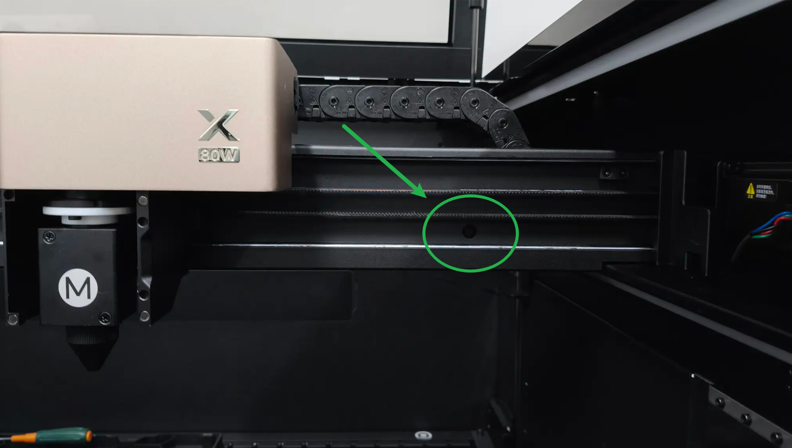
- Move the laser module in front of the hole.
- On the back of the X-axis, place the drag chain on an object to lift it.
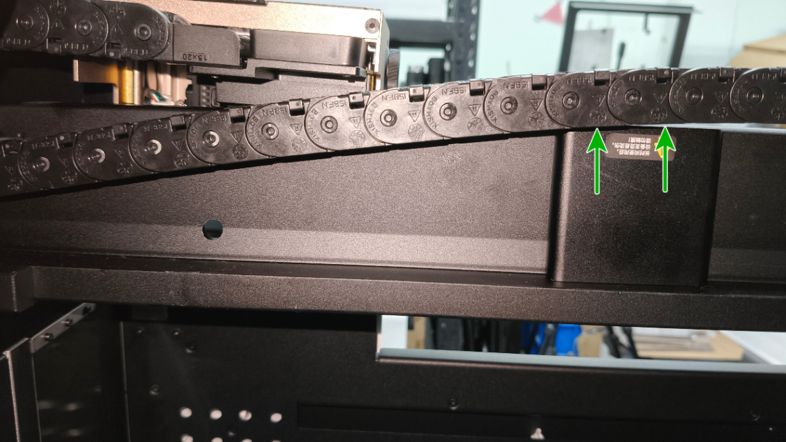
- Move the laser module until its roller's screw fits in the hole on the X-axis.
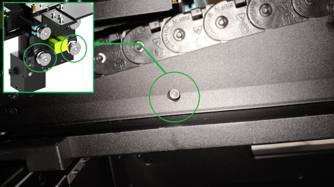
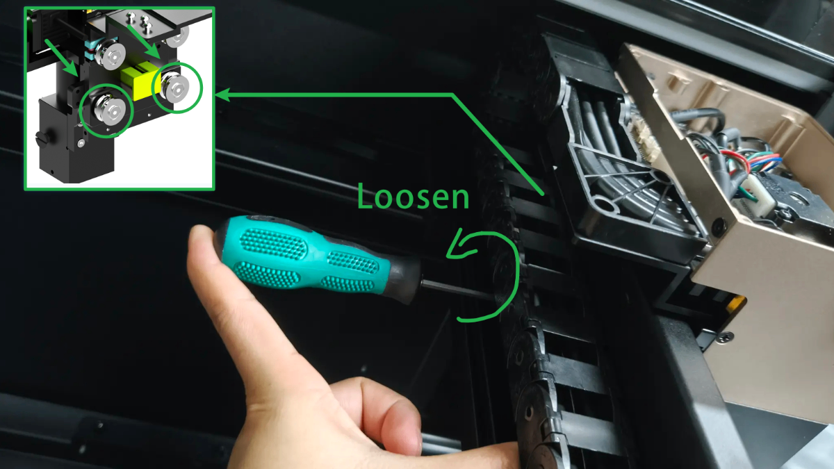
- Follow the method above, use a screwdriver anticlockwise to remove 2 screws and rollers one by one from the laser module.
Install the roller
- Ensure the laser module is placed straight, and two upper rollers on the laser module snap onto the guide rail.
- Place the roller on the guide rail, and align the roller to the hole on the gantry.
- Fit the screw through the hole, and then insert the roller.
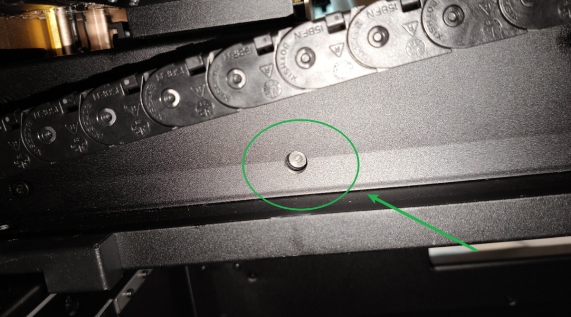
- Hold the X-axis gantry and the bottom of the laser module, lift the laser module upward to align the gantry hole, roller's screw, and the screw hole on the back of the laser module.
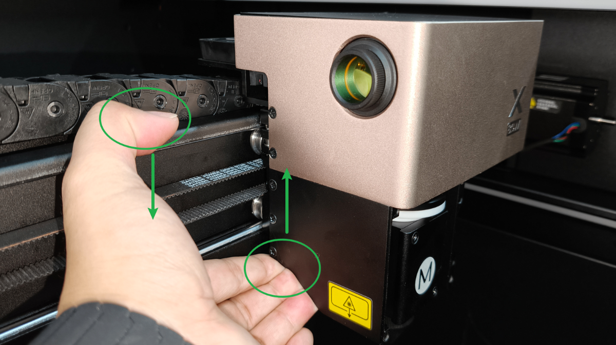
- Tighten the roller's screw clockwise.
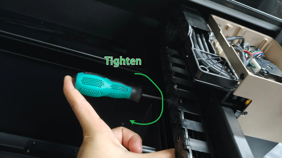
- Follow the method above, secure the other roller.
- Take the drag chain down from an object.
Still experiencing issues?
Should the issue persist after completing the preceding steps, submit a ticket via the "Submit a Ticket" button in the "Help Ticket" section below. The standard response time for xTool Customer Service is one business day.
For a prompt resolution, please include the following details:
- Issue description: A detailed explanation of the observed problem.
- Video evidence: Attach a video demonstrating the issue, where applicable.
- Troubleshooting performed: Any troubleshooting steps you have already attempted, along with their results.
This information is crucial for xTool technical support engineers to provide timely assistance.
Documentation feedback
Help improve this content by providing feedback. If this content did not meet your requirements, select "No" in the "Was this page helpful?" section below. Include specific details about what was unclear or missing in the pop-up suggestion box. Feedback submissions are reviewed by xTool technical writers to enhance future documentation.

Services & Help
Learn & Education

Copyright © 2025 xTool All Rights Reserved.