Meet your helmet
Familiarize yourself with the main components and adjustment points of your helmet before use.
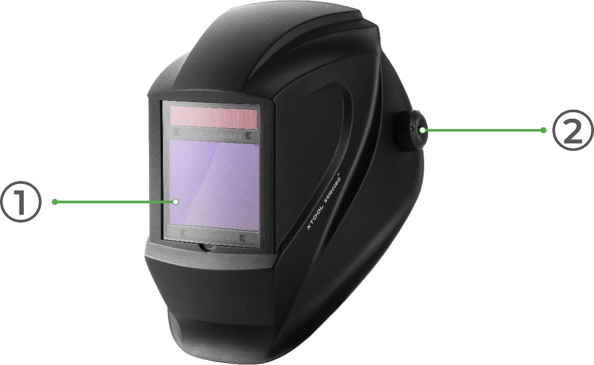
Front & Side View
- Visor: The main protective window.
- Left Knob: Used to adjust the tilt angle and position of the visor for optimal viewing.
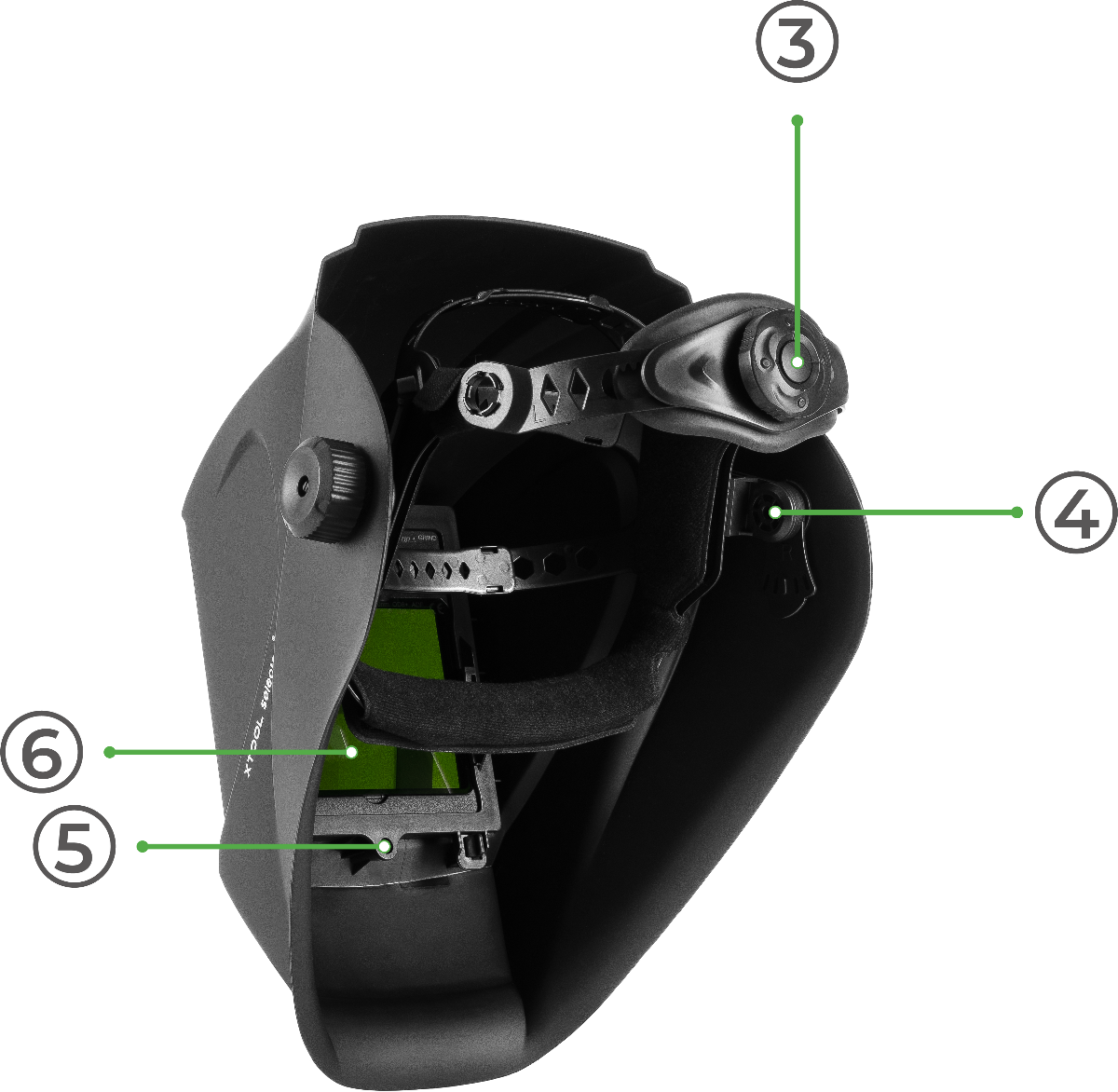
Rear & Side View
- Rear Knob: Used to adjust the tightness of the headband for a secure and comfortable fit.
- Right Knob: Used to adjust the tilt angle and position of the visor for optimal viewing.
- ADF Securing Screw: Hold the filter module in place.
- Auto-Darkening Filter (ADF) Module: The ADF is the electronic screen that automatically darkens to protect your eyes.
Before first use
⚠️ Important: The Auto-Darkening Filter requires two CR2032 3V lithium button batteries (not included). With fresh batteries, the filter provides more than 1,000 hours of continuous use.
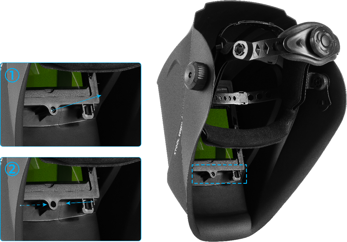
Step 1: Remove the ADF Module
- Use the included screwdriver to remove the ADF securing screw.
- Gently squeeze the two tabs on either side of the screw hole and pull towards the center.
- With your other hand, push the screen mounting frame and the auto-darkening filter out from the inside of the helmet.
Step 2: Access the Battery Trays
- Separate the ADF screen from its black plastic retaining frame.
- Locate the two battery trays at the top of the ADF screen module.
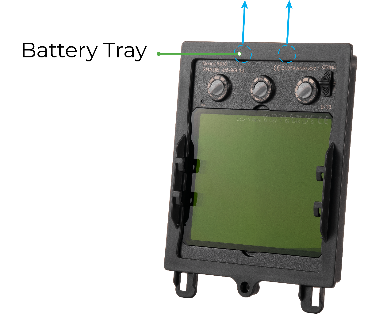
Step 3: Install the Batteries
- Slide each battery tray out.
- Place one CR2032 battery into each tray with the positive (+) side facing UP.
- Slide the trays back into the ADF module until they click into place.
Step 4: Reassemble the Helmet
- Place the ADF screen back into its retaining frame.
- Insert the complete module back into the helmet, securing it with its securing screw. Do not overtighten.
Operating instructions
Adjusting for a comfortable fit
- Adjust Headband Tightness: Place the helmet on your head. Turn the Rear Knob to tighten or loosen the headband until it fits securely and comfortably.
- Adjust Visor Angle: While wearing the helmet, loosen the Left and Right Knobs. Tilt the visor up or down to find the optimal viewing position, then tighten the knobs to lock it in place.
Operating the auto-darkening filter (ADF)
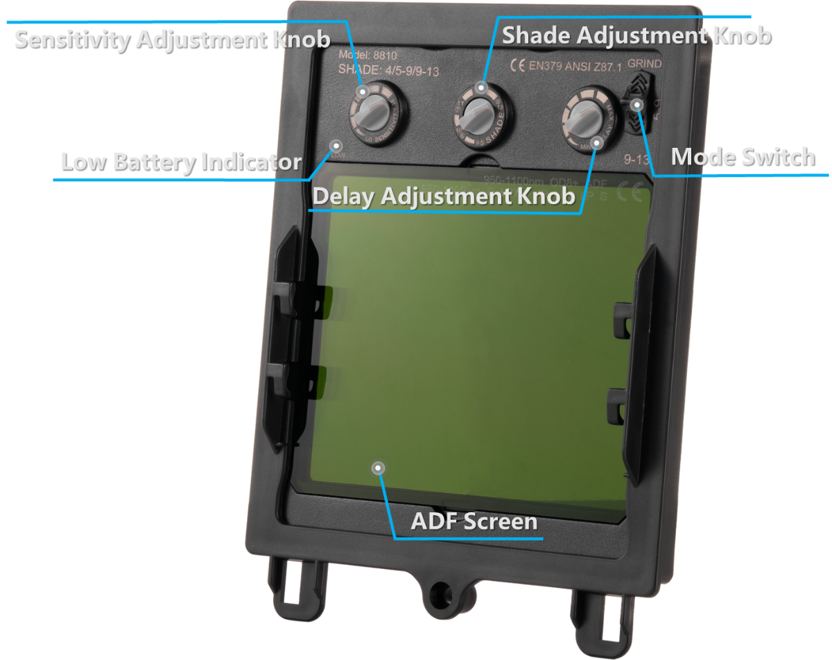
The four controls located at the top of the ADF module enable you to customize the helmet's performance for your specific task.
Control | Function |
Sensitivity Adjustment Knob | Controls how easily the lens darkens in response to light. |
Shade Adjustment Knob | Sets the darkness level of the lens during operation. |
Delay Adjustment Knob | Sets how long the lens stays dark after the laser stops. |
Mode Switch | Selects between Grind Mode (off), low shade range (5-9), and high shade range (9-13). |
Select the operating mode (Mode Switch)
- GRIND – Auto‑darkening is OFF. The lens remains in its light state. Use for grinding or non‑welding tasks.
- Note: Sensitivity, Shade, and Delay adjustments are inactive in this mode.
- 5–9 – Low shade range. Use for lower‑power laser applications.
- 9–13 – High shade range. Use for higher‑power laser applications.
⚠️ IMPORTANT: Before starting any laser welding task, switch to either 5–9 or 9–13 mode to activate auto‑darkening protection. Welding in GRIND mode will not protect your eyes from laser arc light.
Set the shade level (Shade Adjustment Knob)
- This knob's function depends on the mode selected with the Mode Switch.
- In 5–9 mode – Adjusts between shade levels 5, 6, 7, 8, 9.
- In 9–13 mode – Adjusts between shade levels 9, 10, 11, 12, 13.
- Higher numbers = darker shade.
Adjust the sensitivity (Sensitivity Adjustment Knob)
- Controls how much light is required to trigger the darkening function.
- MIN – Lowest sensitivity. Use in bright environments or to prevent darkening from nearby light sources.
- MAX – Highest sensitivity. Use in darker environments or for low‑amperage laser work.
Set the delay (Delay Adjustment Knob)
- Controls how long the lens remains dark after the laser arc stops.
- Range: 0.2 s (MIN) to 1.0 s (MAX).
- MIN – Shortest delay; ideal for quickly switching between tasks.
- MAX – Longest delay; recommended for high‑power applications where the material may still glow after welding stops.
Quick reference
Task Type | Mode | Shade Range | Sensitivity | Delay |
Grinding / Prep Work | GRIND | / | / | / |
Low‑Power Laser Welding | 5–9 | 5–7 | Medium–High | Medium |
High‑Power Laser Welding | 9–13 | 10–12 | High | Long |
Documentation feedback
Help improve this content by providing feedback. If this content did not meet your requirements, select "No" in the "Was this page helpful?" section below. Include specific details about what was unclear or missing in the pop-up suggestion box. Feedback submissions are reviewed by xTool technical writers to enhance future documentation.
