Introduction
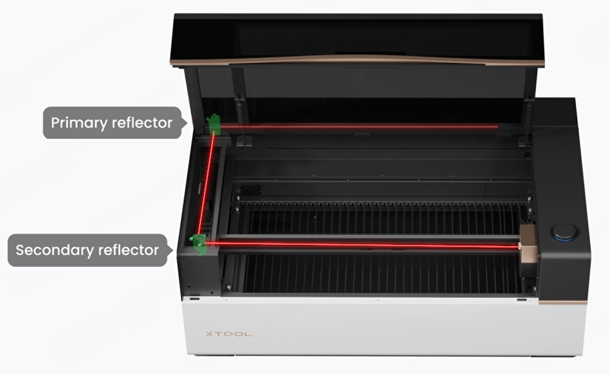
The optical path of xTool P3 includes the laser optical path and the coaxial red light optical path. The precision of the laser optical path directly affects the size and position of the laser spot, which also affects the processing result. The coaxial red light visualizes the laser position, making it easier for you to inspect and calibrate the optical path and observe the processing location. Therefore, ensure the optical path functions properly before using the device.
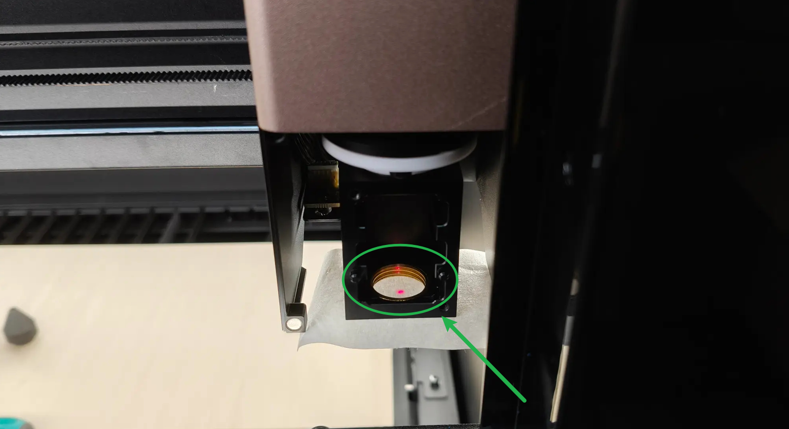
When the optical path is functioning normally, the spot of the coaxial red light and the laser spot should overlap, and their reflection angles should be the same.
For CO2 laser devices, consumables such as laser mirrors, focus lenses, and laser tubes require optical path recalibration after cleaning or replacement. Therefore, users of CO2 laser devices typically need to master optical path calibration methods, so as to ensure long-term device performance. You can follow the guidance of this article to learn.
Applicable scenarios
- Unboxing for first use;
- After the replacement of the laser mirror or laser lens;
- After the replacement of the laser tube;
- After the device transportation;
- After the replacement of the laser mirror holder or the beam combiner holder;
- Laser power is decreasing;
- The laser module cannot emit the laser (but the laser tube lights up);
- Scenarios that may affect the optical path or be affected by the optical path, and so on.
Matters need attention
1. Check every mirror before the operation
Before you calibrate the optical path, check if the laser mirrors, laser window, and focus lens are installed properly.
2. Remove the residues on the lifting platform
During calibration, the laser module will move over a wide range. If thick or tall materials are placed on the lifting platform, the laser module may hit the material.
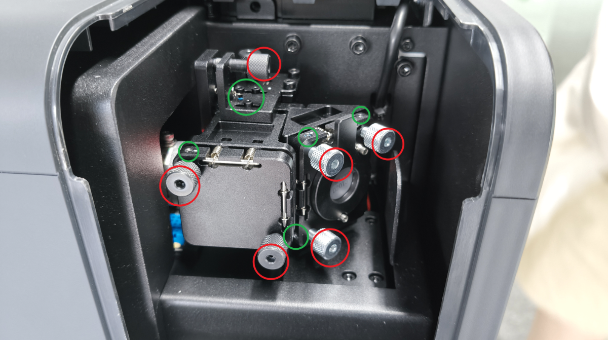
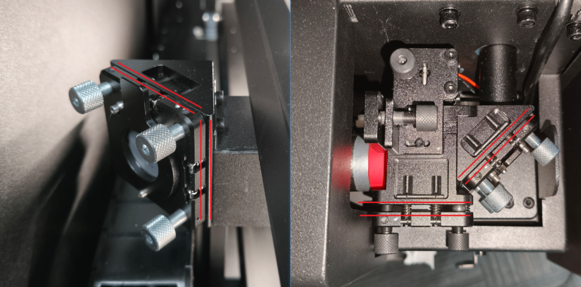
3. Loosen the set screws
Before adjusting the optical path, first loosen the set screws without removing them, then loosen the thumb screws. After the optical path is calibrated, retighten the set screws.
For example, the red ones are optical path adjustment screws, and the green ones are set screws. The set screw can be adjusted using the 1.5 mm hex key that is included in the pack of xTool P3.
4. Precautions on adjusting the set screws
(1) Insert the hex key vertically all the way in before tightening.
(2) Do not overtighten the set screws to prevent damage during adjustment.
5. Precautions on adjusting the thumb screws
(1) Do not adjust the same screw in the same direction drastically. Otherwise, it may cause severe misalignment of the optical path.
(2) The adjustment screw cannot be left unscrewed. Otherwise, it will affect the stability of the optical path. When the screw is loose enough, it will be in a suspended state, and if you continue to loosen it, you will not be able to further adjust the optical path.
FAQs
1. I can't see the coaxial red light spot. Why?
Troubleshoot according to the article: xTool P3 Coaxial Red Light Won't Light Up.
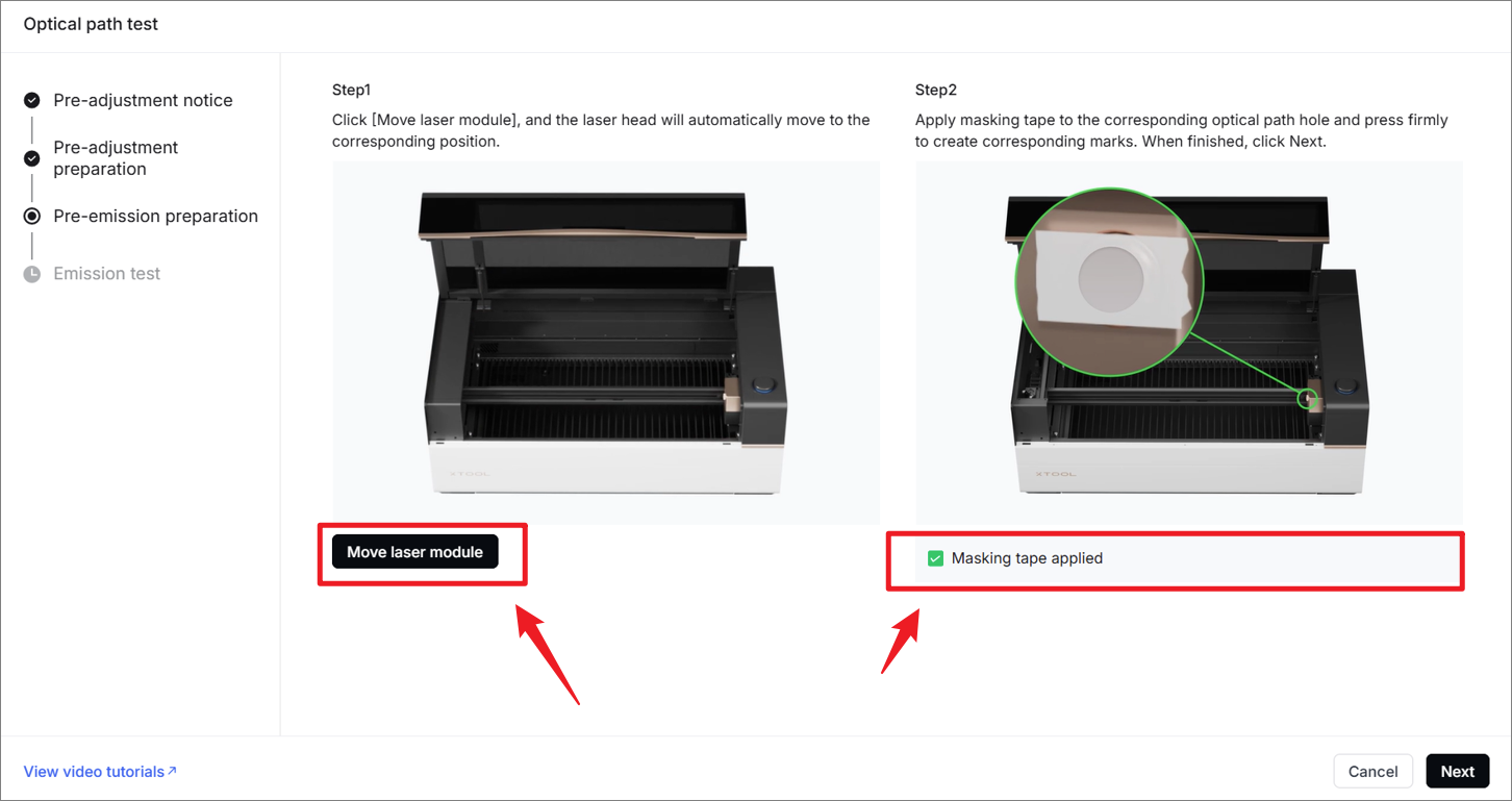
2. I can't see the laser burning mark on the masking tape. Why?
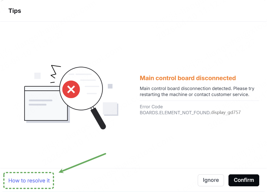
(1) Check if the software displays any pop-up windows indicating a device malfunction:
- If so, the laser will not function. Please follow the instructions in the error pop-up or contact our official customer service team to resolve the hardware issue first.
- If not, proceed to the next step.
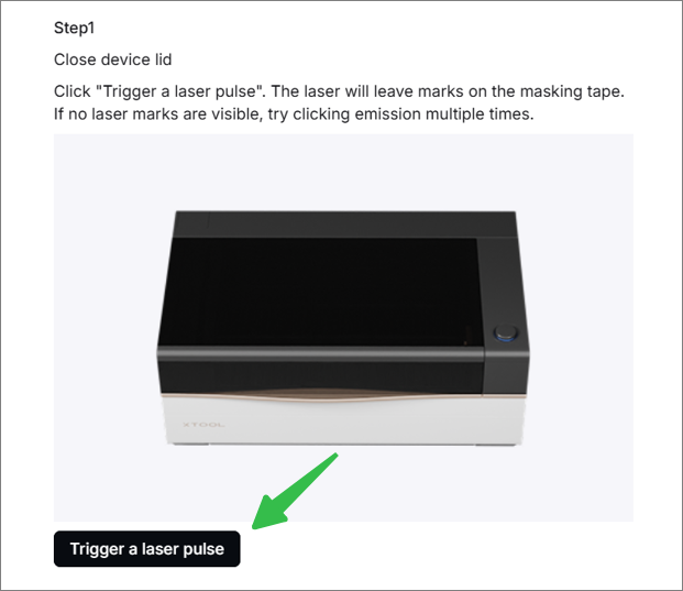
(2) Trigger a laser pulse a few times. If the burning mark still doesn't appear, go to the next step.
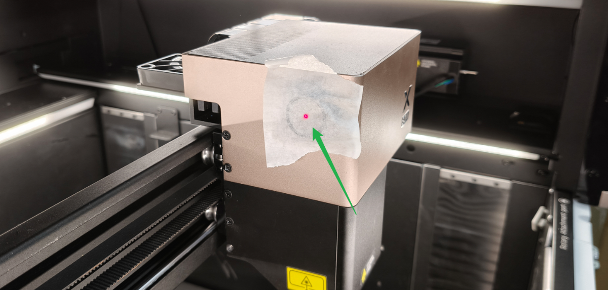
(3) Trigger a laser pulse and observe the moment of the laser pulse. Or perform a short-time processing with 50% power.
And then observe whether the laser tube emits light at the primary mirror holder during processing:
After clicking the laser pulse button, the laser tube will only illuminate for 0.5 seconds. Please pay attention to it.
- If the laser tube does not light up, read the article to check for the reason: xTool P3 Laser Tube Won't Light Up
- If the laser tube lights up, continue the next steps.
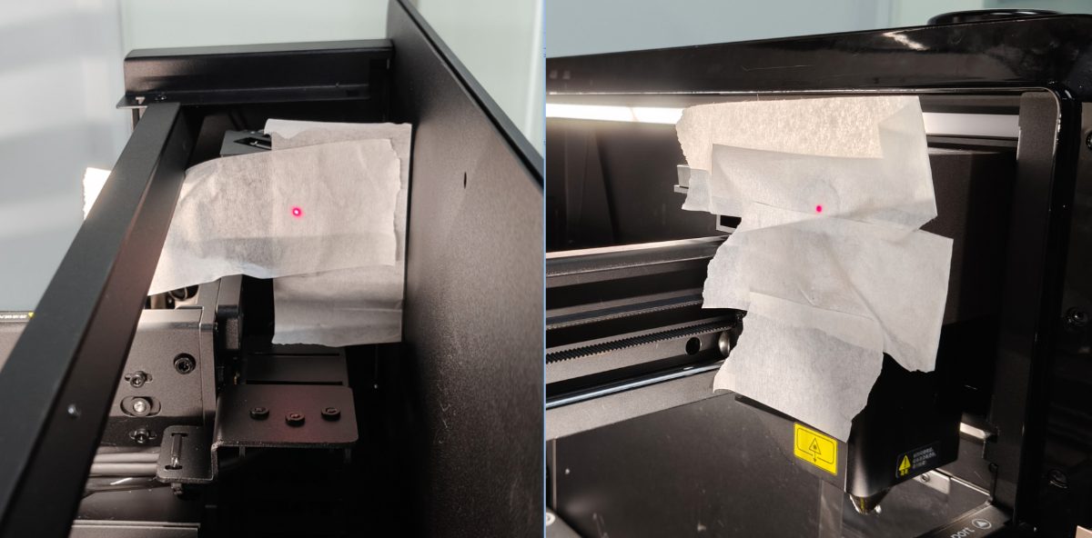
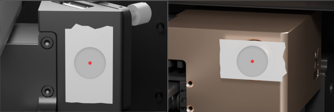
(4) Increase the area of the masking paper before triggering a laser pulse. If the masking tape length is insufficient, you may substitute it with masking tape secured to A4 paper.
3. I can't proceed to the next step in the software. Why?
Due to resolution differences, some displays may not show the full interface, resulting in required fields not appearing. Please scroll over the software, check the required fields, and then click Next.
4. The red dot moves while tightening the set screws. Why?
(1) Check whether the laser mirror holder is loose. If loose, tighten the screws on it.
(2) When tightening the set screw during the final few turns, the red light may be slightly offset due to the increased force on the laser mirror, which can be improved by tightening the set screw gradually in half-turn increments.
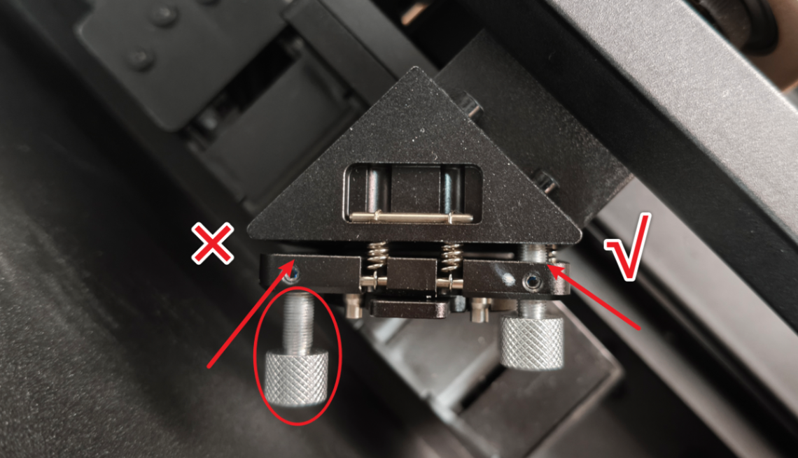
5. The optical path is severely tilted. What can I do?
If you find that the laser tube emits light but the optical path is misaligned, and you are unsure how to adjust it back, please first adjust the adjustment blocks and brackets of each mirror holder completely parallel (as shown) before performing optical path calibration.
In this state, the optical path typically exhibits minimal deviation. You can calibrate the optical path again according to the instructions provided in the software.
6. The set screw is stripping. What can I do?
If stripping occurs when loosening the set screw, try to insert a hex key vertically into the hole, then slowly bend the hex key to increase friction before loosening again.
Once the stripped screw is loosened, do not retighten. Replace it with a new one.
7. The burn holes on the masking tape are too large. What should I do?
Apply two layers of masking tape.
8. What is the difference between the proximal adjustment screw and the distal adjustment screw at the combiner mirror holder?
- The proximal adjustment screw directly controls the vertical or horizontal movement of the red laser, which is used to adjust the overlap between the red light and the laser. It provides a very slight adjustment range for the red light position.
- The distal adjustment screw controls the reflection angle of the red light, which is used to adjust the overlap of the reflection angles between the red light and the laser. It provides a great adjustment range for the red light position.
9. After adjusting the optical path, should the set screw (small screw) on the adjustment screw be tightened?
The screws on the combiner mirror holder should be tightened slightly. The screws on the primary and secondary mirror holders are no need to be tightened or only be slightly tightened (as they require regular inspection and adjustment).
10. Does the laser spot have to be positioned exactly at the center?
It should be roughly located in the center. Due to assembly tolerances, the axes are not perfectly perpendicular. As long as the spot falls at the center of the focus lens, it may deviate from the center on other lenses.
11. The optical path is not calibrated properly all the time. What should I do?
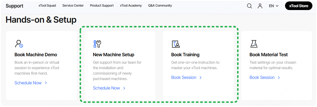
After confirming that the laser tube emits light normally during processing as per FAQ #2, you may click the link to request Machine Setup or training services. Host will provide professional video guidance or on-the-spot service:
- Setup service: Offered via online video and on-the-spot service (in certain areas), with local branches arranging hosts to provide service.
- Training service: You can directly select the desired host and service method according to the distribution of hosts in your region.
All services listed above are paid services, priced at approximately $70 to $100 per hour, and typically completed within one hour.
Hosts may not be available in certain regions. Please contact xTool after-sales service for help.
Adjustment procedures
All adjustment directions described below are based on your position at the current adjustment point, facing the direction of the next class optical path.
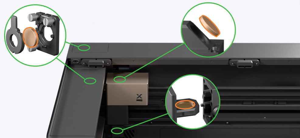
1. Combiner mirror holder
The combiner mirror holder sits next to the primary mirror holder, which is used to adjust the overlap of the coaxial red light with the laser and their reflection angles. The combiner mirror holder can only adjust the optical path of the coaxial red light and cannot adjust the laser optical path.
Follow the guide to find the combiner mirror holder:
1.1 Vertical adjustment screw at the proximal end of the coaxial red light
You can control the coaxial red light up and down by rotating the screw (highlighted in red). It is usually adjusted near the position where the secondary mirror holder meets the primary mirror holder.
Rotate the screw clockwise to control the coaxial red light moving vertically downwards. Rotate the screw anticlockwise to control the coaxial red light moving vertically upwards.
1.2 Horizontal adjustment screw at the proximal end of the coaxial red light
You can control the coaxial red light horizontally by rotating the screw (highlighted in red). It is usually adjusted near the position where the secondary mirror holder meets the primary mirror holder.
Rotate the screw clockwise to control the coaxial red light moving horizontally leftwards. Rotate the screw anticlockwise to control the coaxial red light moving horizontally rightwards.
1.3 Upper left adjustment screw at the distal end of the coaxial red light
You can control the coaxial red light's reflection angle by rotating the screw (highlighted in red).
Rotate the screw clockwise to control the coaxial red light moving right. Rotate the screw anticlockwise to control the coaxial red light moving left.
1.4 Bottom right adjustment screw at the distal end of the coaxial red light
You can control the coaxial red light's reflection angle by rotating the screw (highlighted in red).
Rotate the screw clockwise to control the coaxial red light moving down. Rotate the screw anticlockwise to control the coaxial red light moving up.
2. Primary mirror holder
The primary mirror holder can adjust the reflection angle of the coaxial red light and laser at the same time. Usually, the adjustment sequence for the primary mirror is performed after the coaxial red light and laser paths have been aligned to nearly overlap.
Follow the guide to find the primary mirror holder:
2.1 Upper right adjustment screw at the primary mirror holder
Rotate the screw clockwise to move the whole optical path to the right. Rotate the screw anticlockwise to move the whole optical path to the left.
2.2 Upper left adjustment screw at the primary mirror holder
Rotate the screw clockwise to move the whole optical path to the upper left. Rotate the screw anticlockwise to move the whole optical path to the bottom right.
2.3 Bottom left adjustment screw at the primary mirror holder
Rotate the screw clockwise to move the whole optical path downward. Rotate the screw anticlockwise to move the whole optical path upward.
3. Secondary mirror holder
The secondary mirror holder can adjust the reflection angle of the coaxial red light and laser at the same time. Usually, the adjustment sequence of the secondary mirror follows the completion of primary mirror alignment.
Follow the guide to find the secondary mirror holder:
3.1 Upper left adjustment screw at the secondary mirror holder
Rotate the screw clockwise to move the whole optical path to the left. Rotate the screw anticlockwise to move the whole optical path to the right.
3.2 Upper right adjustment screw at the secondary mirror holder
Rotate the screw clockwise to move the whole optical path to the upper right. Rotate the screw anticlockwise to move the whole optical path to the bottom left.
3.3 Bottom right adjustment screw at the secondary mirror holder
Rotate the screw clockwise to move the whole optical path upward. Rotate the screw anticlockwise to move the whole optical path downward.
4. Tertiary mirror holder
The tertiary mirror is set at a fixed angle and cannot be adjusted. Different from the magnetic fastening used for the primary and secondary mirrors, the tertiary mirror is secured with a threaded connection (highlighted in red). Turn clockwise to tighten, turn counterclockwise to loosen.
Calibration procedures
1. Connect xTool P3 to xTool Studio.
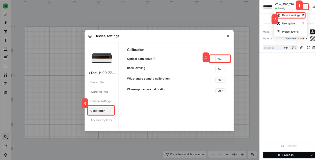
2. Go to ··· > Device settings > Calibration > Start. Start the optical path setup.
3. Follow the steps in the software to test the optical path.
(1) Overlap: The optical paths of the laser and red light overlap.
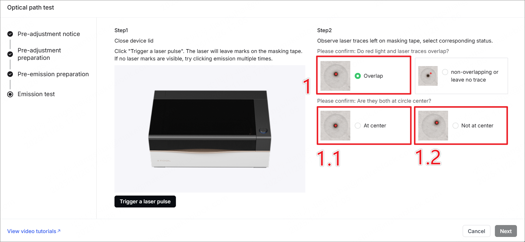
- 1.1 At center: The optical path works normally. Click Next to complete the calibration.
- 1.2 Not at center: The laser optical path and red light path overlap, but the reflection angles are incorrect. Please click Next and follow the software instructions to adjust the reflection angles of the primary and secondary mirrors to complete the calibration.
(2) Non-overlapping or leave no trace: The optical path tilts severely. The laser optical path and red light path do not overlap, and the reflection angle is incorrect.
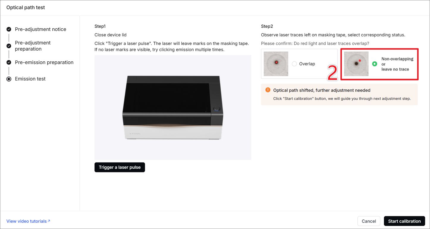
- Click Start calibration.
- According to the software instructions, the laser and red light are adjusted to overlap, and then the angle of reflection of the optical path is adjusted so that the red spot is in the center of the secondary mirror and the laser window before calibration.
Still experiencing issues?
Should the issue persist after completing the preceding steps, submit a ticket via the "Submit a Ticket" button in the "Help Ticket" section below. The standard response time for xTool Customer Service is one business day.
For a prompt resolution, please include the following details:
- Issue description: A detailed explanation of the observed problem.
- Video evidence: Attach a video demonstrating the issue, where applicable.
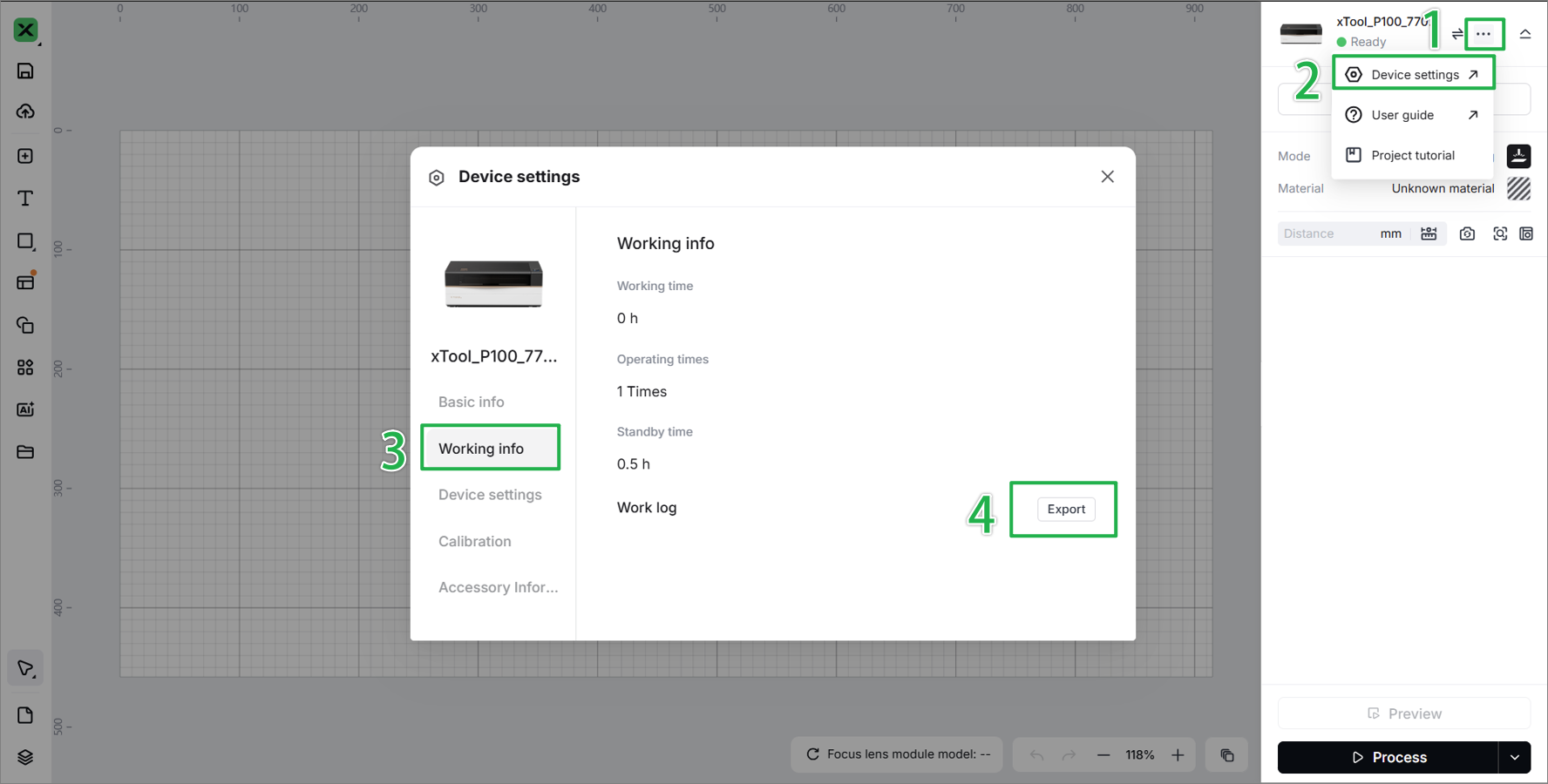
- Device information: Follow the steps to find the SN and export the work log.
- Troubleshooting performed: Any troubleshooting steps you have already attempted, along with their results.
This information is crucial for xTool technical support engineers to provide timely assistance.
Documentation feedback
Help improve this content by providing feedback. If this content did not meet your requirements, select "No" in the "Was this page helpful?" section below. Include specific details about what was unclear or missing in the pop-up suggestion box. Feedback submissions are reviewed by xTool technical writers to enhance future documentation.
