Issue description
This issue occurs when:
- xTool materials cannot be cut through using the recommended parameters
or
- Materials that were previously cut through successfully with the same parameters can no longer be cut through.
Refer to the following for troubleshooting.
Prerequisite
Failure to cut through the material is a common issue in CO₂ laser processing. We can quickly determine whether there is a hardware fault by checking the following aspects:
- Check the focus: When correctly focused, the distance between the air nozzle and the material surface should be approximately 4 mm (applicable to all three focus lenses). If the actual distance is significantly greater or less than 4 mm, it indicates the processing was not properly focused.
- Determine whether the optical path is misaligned: When the optical path is misaligned, the laser cannot accurately pass through the focus lens in all processing areas. This may cause no laser output in certain areas, or cutting may work normally at first, but when the processing position changes, the laser power may drop significantly or disappear completely.
- Check whether the lenses are dirty: Oxidation or contamination on the lenses can reduce the laser’s reflectivity or transmittance, thereby affecting the final output power. Note that slight oxidation or discoloration usually does not noticeably affect laser power, and the lenses can still be used normally.
Potential causes
- Incorrect processing parameters
- Improper material placement
- Misaligned optical path
- Optical lens abnormality
- Laser tube power degradation
- The processing surface is uneven
- Insufficient airflow from the air pump
- Laser tube failure or damage
Troubleshooting procedures
1. Check processing parameters
Parameter Verification:
- xTool materials: Verify that processing parameters match the current material type.
- Non-xTool materials: Use the Material Test Array function to determine optimal parameters.
- If parameters are appropriate, proceed to the next step.
If the material fails to cut through only in conveyor feeder mode, increase the power or reduce the cutting speed. This occurs because the motor transmission rate in the conveyor feeder mode differs from that in the lift platform mode.
2. Check the position of the materials
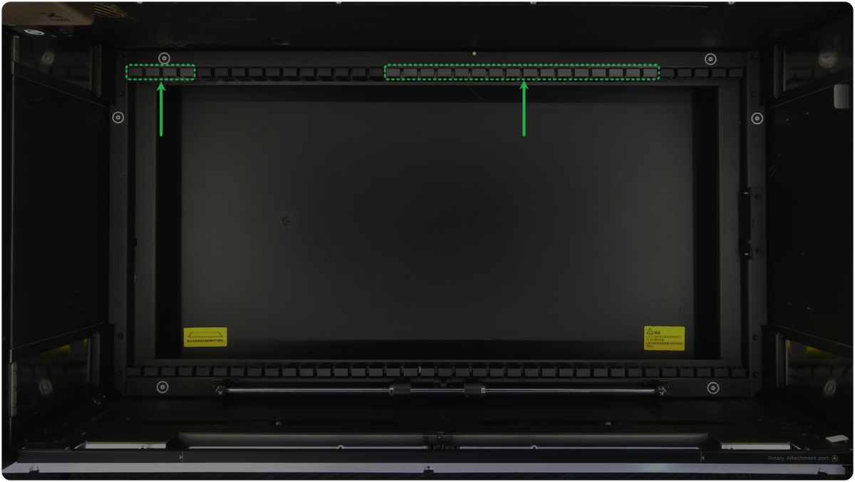
The origin and the right slat slots (as shown) are the calibration points for distance measurement. Do not cover them with the materials, as this may cause defocusing.
3. Check the laser mirrors
⚠️ Safety First: Power off your laser device before performing the inspection in this step.
Check each of the three laser mirrors for oxidation, dirt, or other abnormal conditions.
To uninstall or clean the laser mirrors, see the tutorial.
First-level Laser Mirror
Second-level Laser Mirror
Third-level Laser Mirror
- If the mirrors are dirty, please follow the tutorial and clean them.
- If the mirrors are oxidized severely, please replace them with new ones.
4. Check the protective lens
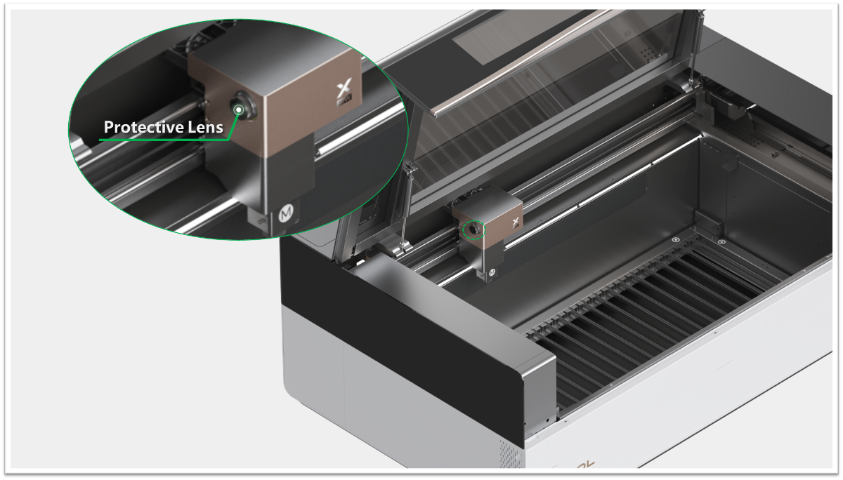
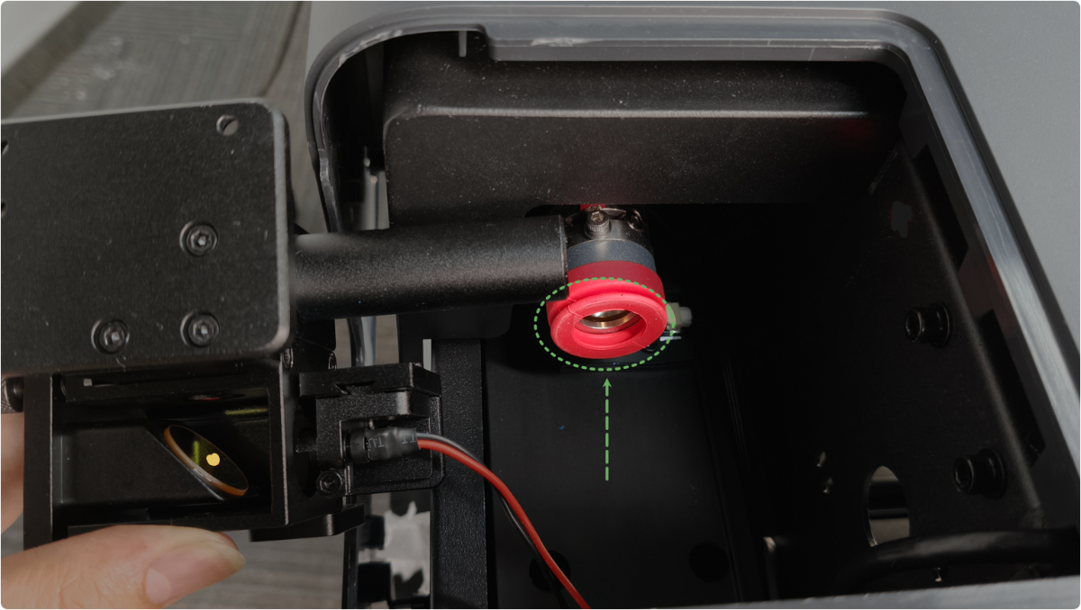
Rotate the protective lens counterclockwise to remove it, then inspect for abnormalities such as oxidation or contamination.
To uninstall or clean the laser mirrors, see the tutorial.
- If the lens is contaminated, follow the tutorial to clean it.
- If the lens is oxidized or damaged, replace it in a timely manner.
5. Check the focus lens
(1) Remove the magnetic front cover.
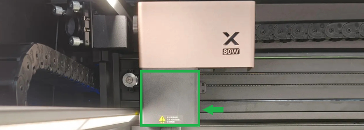
(2) Use a Phillips screwdriver to remove the screws on the focus lens holder.
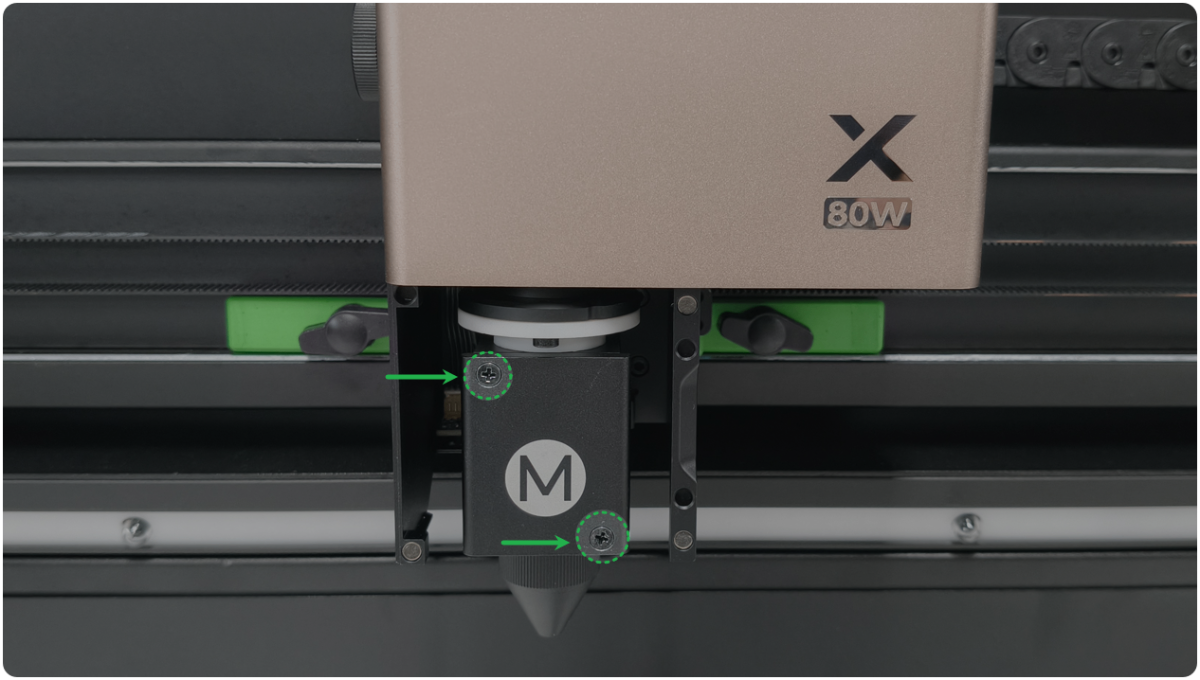
(3) Take out the focus lens holder. Check whether the focus lens is damaged or dirty.
To uninstall or clean the laser mirrors, see the tutorial.
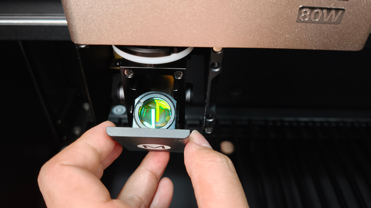
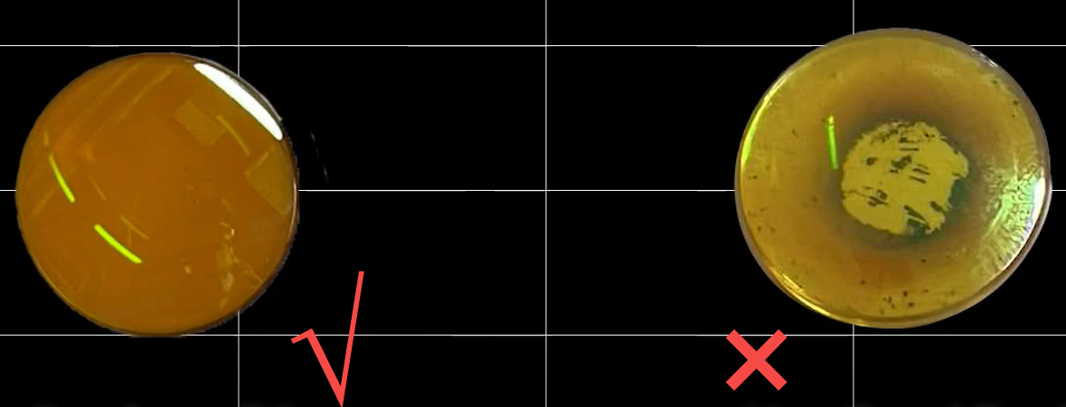
- If the lens is contaminated, follow the tutorial to clean it.
- If the lens is broken or oxidized severely, replace it in a timely manner.
6. Check the flatness of the surface to be processed
- For the material, if the material is uneven, flatten it or replace it with a flat piece.
- For the baseplate, make sure all the slats are fully snapped into place and positioned flat.
- For the honeycomb panel:
- Clean any debris from the area where the honeycomb panels are to be placed and lay them flat.
- Check the honeycomb panel for any distortion or dents (especially with non-official honeycomb panels). If any are found, process with slats or replace it with a new one.
7. Check the focus lens installation orientation
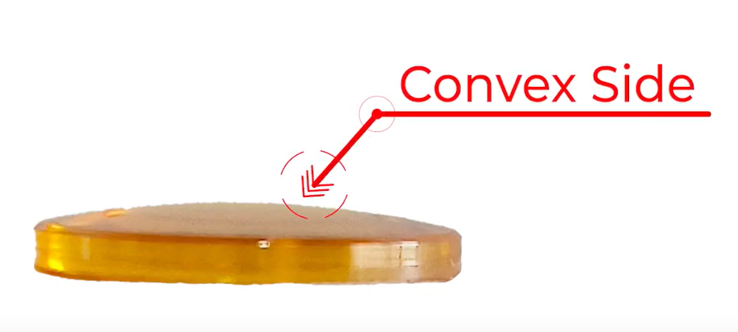
Critical Check: Ensure the focus lens is installed with the convex side facing up.
Method 1: Visual Inspection
- Remove the focus lens from its holder.
- Observe the lens shape.
- Correct installation: Convex (curved outward) side faces up.
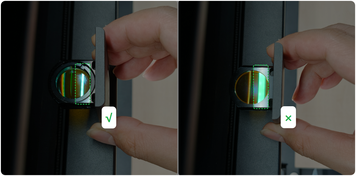
Method 2: Light Reflection Test
- Place the focus lens holder vertically under the left side light panel of the machine.
- Observe the reflected light.
- Correct orientation: The surface that produces a narrower reflected light beam is the convex side and should face up.
8. Check the model of the focus lens (if any)
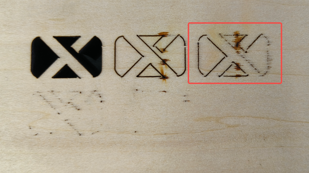
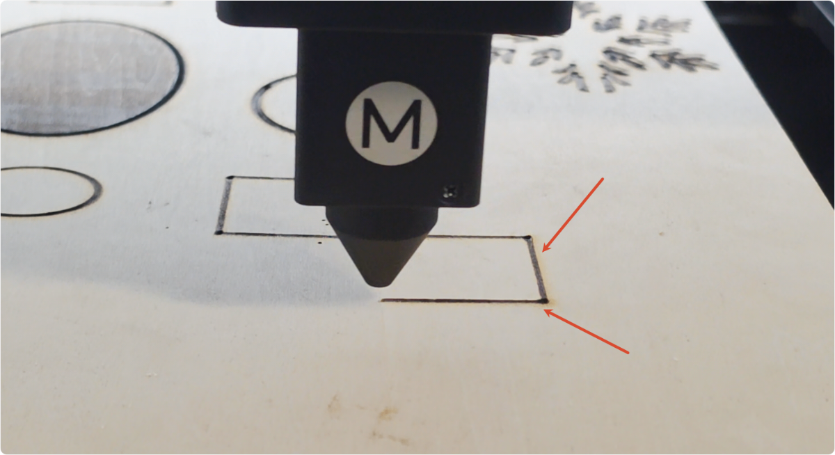
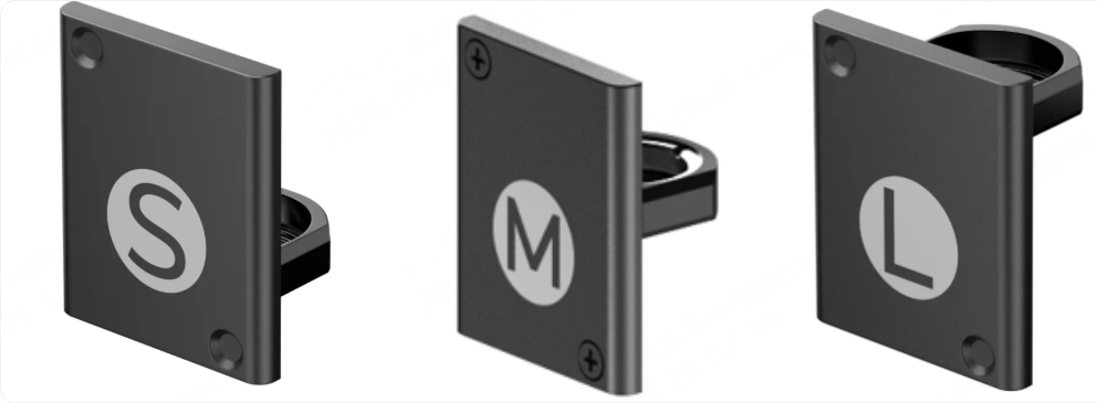
xTool P3 comes standard with an M-sized focus lens. The focus lens and holder must be used together. Otherwise, the image will be out of focus, resulting in a very rough cutting path (as shown below).
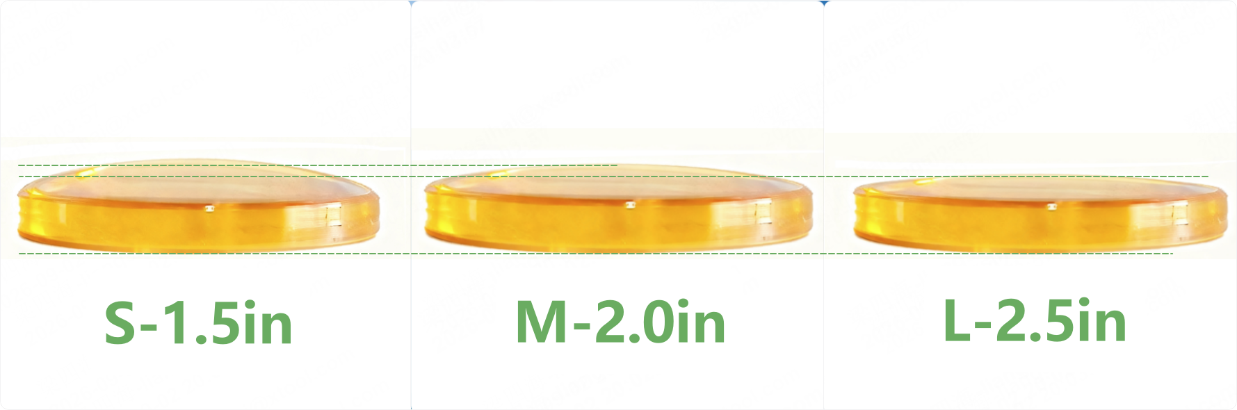
If you have other sizes of focus lenses, make sure the focus lens matches its holder. You can distinguish the models by the markings on the packaging. If they cannot be distinguished by the packaging, observe the degree of lens curvature: the shorter the focal length, the more convex the lens is. For example, curvature height: S > M > L.
9. Check the optical path
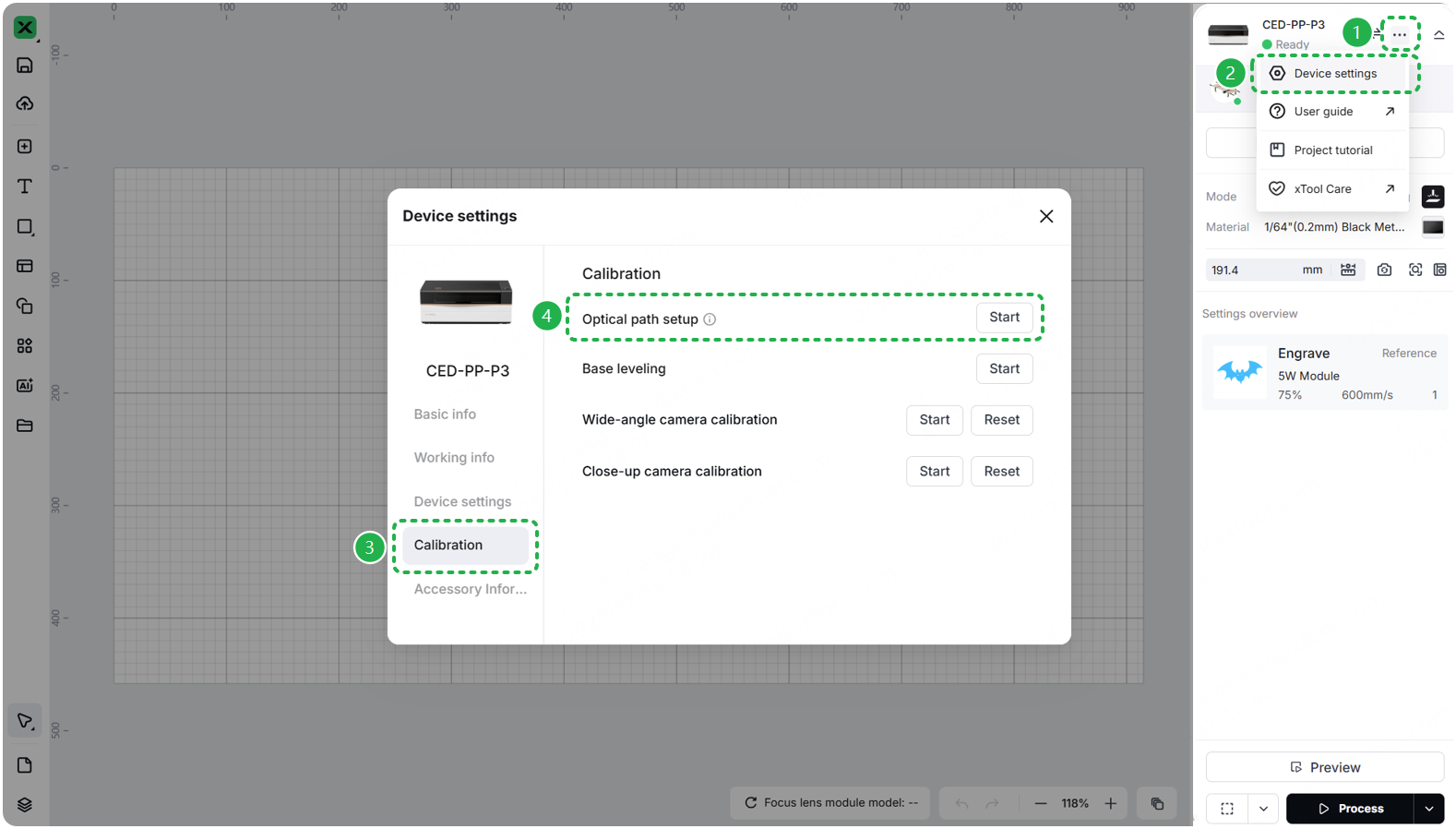
Go to ··· > Device settings > Calibration > Optical path setup > Start to calibrate the optical path. Test whether the optical path is misaligned.
Cutting abnormalities caused by misaligned optical paths often result in significant variations in cutting performance in different processing areas, with some areas even failing to emit light. You may also attempt cutting tests in different areas. If you need to calibrate the optical path, see the tutorial.
- If the optical path is misaligned, please refer to the guide and software prompts to complete the calibration.
- If the optical path is aligned, exit the settings and check for other issues.
10. Laser tube power degradation
For most CO₂ laser engraving and cutting systems, laser tube power degradation can occur under two main conditions:
Normal Power Degradation (Irreversible)
Description:
Over time, the laser tube’s output power gradually decreases due to normal wear. This decline is permanent and cannot be reversed.
Signs of Power Degradation:
- Previously successful cuts now require higher power.
- Cutting performance gradually decreases over time.
- Longer cutting times are needed for the same results.
Compensation Methods:
- Increase laser power for your current project.
- Decrease cutting speed to allow more energy per area.
- Multiple passes may be necessary for thick materials.
Temperature‑Related Power Loss (Reversible)
Description:
When the device temperature becomes too high, the laser output power may drop temporarily. This effect is reversible once the system cools.
💡 Tip: Antifreeze is added to the water tank to prevent freezing when ambient temperatures fall below 0 °C, which would otherwise block water circulation. Its primary function, however, is still to cool the laser tube.👉 Always follow the user manual for detailed mixing and filling instructions.
- If your local temperature never drops below 0 °C, simply add 1,200 ml of purified water to the tank.
- If temperatures may drop below 0 °C, mix antifreeze and purified water in the recommended ratio.
Temperature Management:
- More common during extended continuous processing.
- Solution: Stop processing and allow the machine to cool down.
- Test cutting performance after the cooling period.
11. Check the airflow of the air pump
The airflow from the air pump affects cutting performance differently depending on the thickness of the wood board:
- When cutting thin wood boards, the auxiliary airflow is mainly used to reduce yellowing on the material surface and has little effect on cutting capability.
- When cutting thick wood boards, the auxiliary airflow can significantly affect cutting capability. If your xTool P3 can cut thin wood boards normally using the recommended parameters, but its ability to cut thick wood boards is noticeably worse than before, it may be related to abnormal airflow. You can follow the link to check and troubleshoot airflow issues during cutting.
12. Check the beam combiner mirror
Go to the link and check whether the beam combiner mirror works properly.
- If the mirror is clean, reinstall it and recalibrate the optical path.
- If there is some dust or dirt on the surface, clean the beam combiner mirror following this tutorial.
- If the mirror is severely oxidized or cracked, get a new beam combiner mirror for replacement.
13. Check the mirror of the laser tube
- Unplug the power cable, then remove the primary mirror holder and the beam combiner mirror holder following the tutorial.
- Observe the lens on the laser tube through the mounting space of the primary mirror holder:
- If the lens is clean and clear, reinstall the lens holder and realign the optical path.
- If there is dirt on the lens, use a lint-free cloth dampened with alcohol to gently wipe it.
- If the lens is severely oxidized or cracked, replace the laser tube.
Still experiencing issues?
Should the issue persist after completing the preceding steps, submit a ticket via the "Submit a Ticket" button in the "Help Ticket" section below. The standard response time for xTool Customer Service is one business day.
For a prompt resolution, please include the following details:
- Issue description: A detailed explanation of the observed problem.
- Video evidence: Attach a video demonstrating the issue, where applicable.
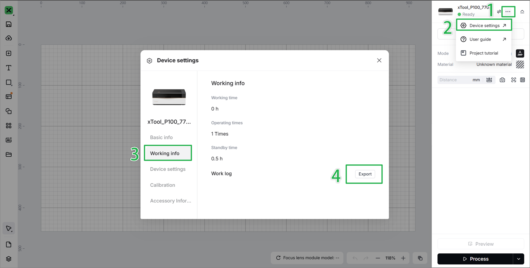
- Device information: Follow the steps to find the SN and export the work log.
- Troubleshooting performed: Any troubleshooting steps you have already attempted, along with their results.
This information is crucial for xTool technical support engineers to provide timely assistance.
Documentation feedback
Help improve this content by providing feedback. If this content did not meet your requirements, select "No" in the "Was this page helpful?" section below. Include specific details about what was unclear or missing in the pop-up suggestion box. Feedback submissions are reviewed by xTool technical writers to enhance future documentation.