This article describes the complete process of using xTool Rotary Attachment 3 (hereinafter referred to as RA3) for cylindrical workpieces on xTool P3.
For more information about RA3, refer to xTool Rotary Attachment 3 User Guide.
Preparations
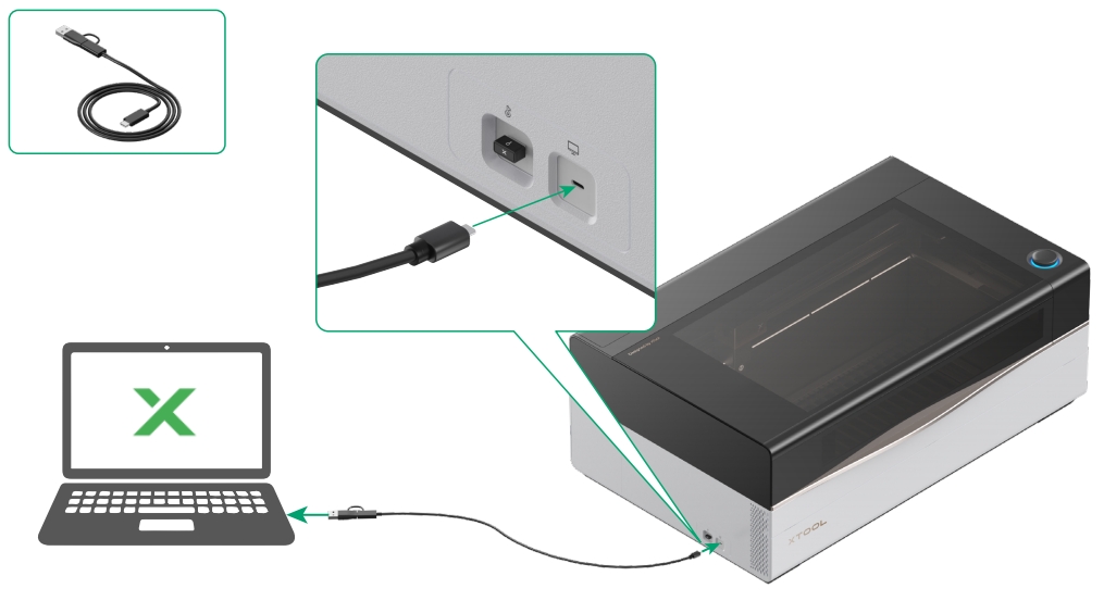
- Turn on xTool P3, and use the USB cable included in the P3 package to connect it to your computer.
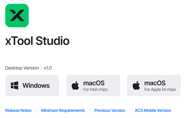
- Download and install the xTool software.
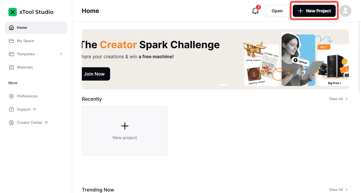
- Open the software and select “+ New Project”.
- Select the icon on the left of the menu button (…).
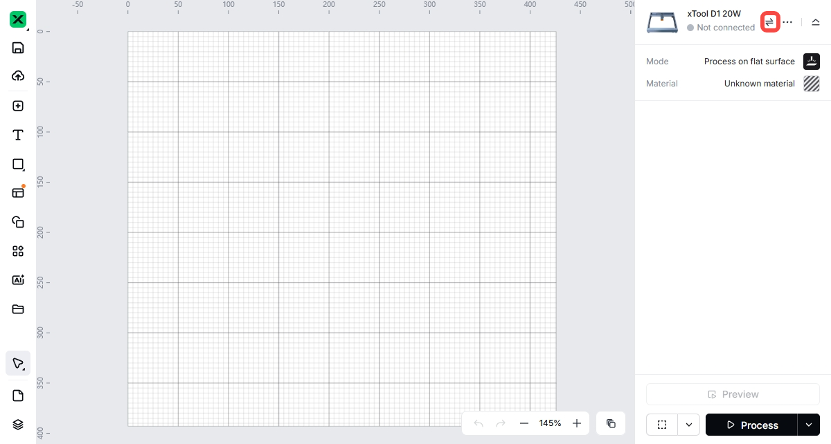
- Select "+ Add Device".
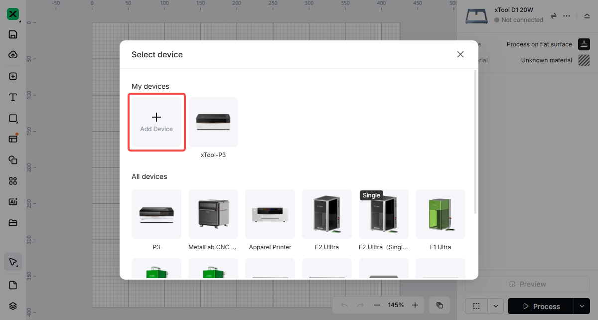
- In the “Connect device” interface, under the “USB” tab, select the P3 device connected to your computer.
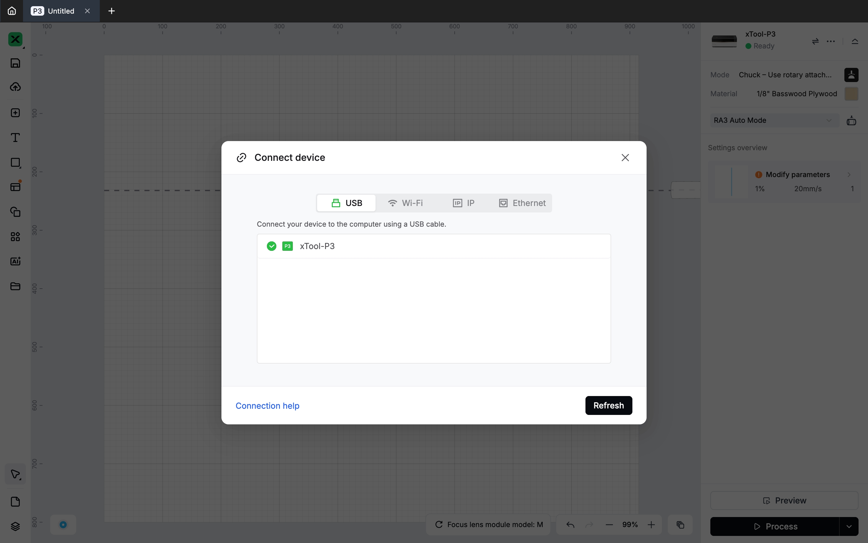
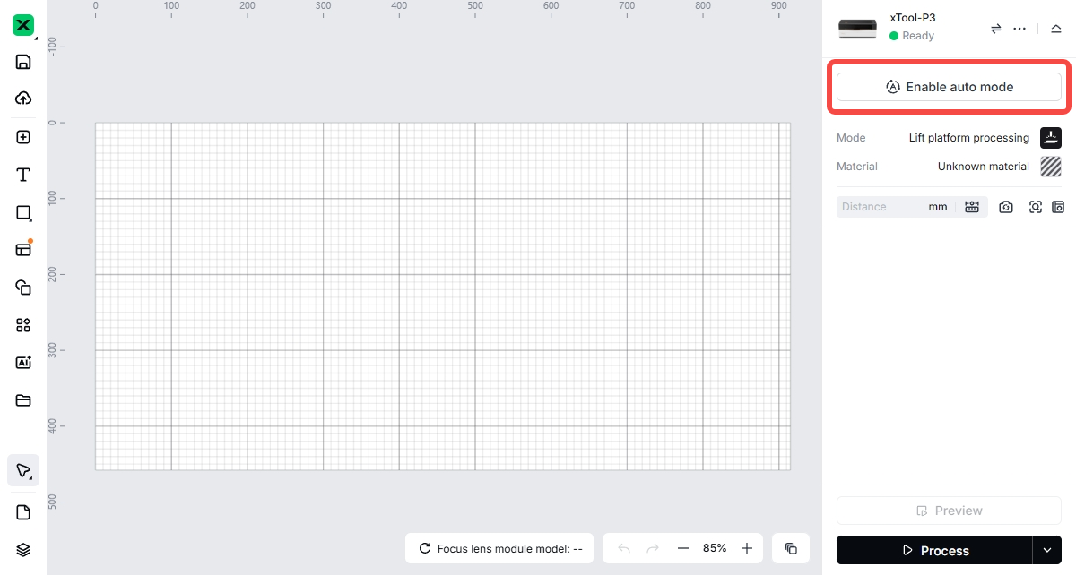
- Once the connection is successful, the device status will show "Ready". Select “Enable auto mode”.
Auto mode
The following uses the jaw chuck mode of RA3 as an example to illustrate the operation method in auto mode.
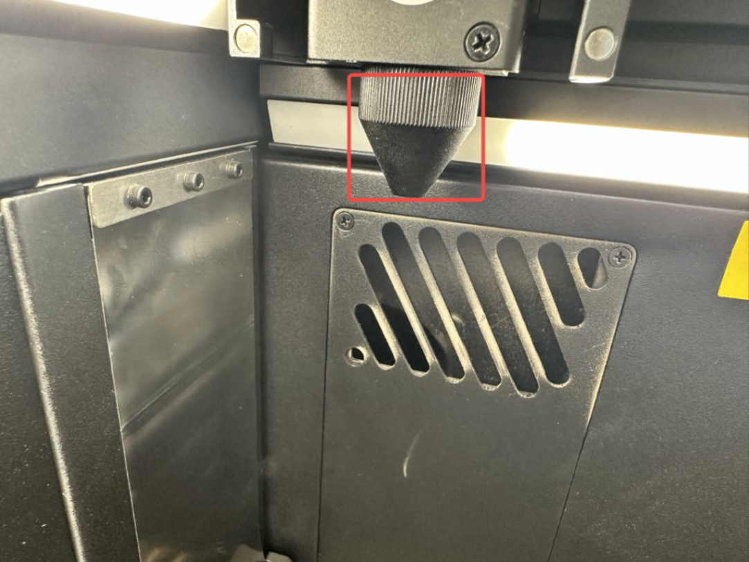
- Open the lid of xTool P3 and remove the nozzle from the laser module. This operation enlarges the working area and prevents the nozzle from colliding with the workpiece on RA3 during processing.
- Fix the power module on the main baseplate of RA3.
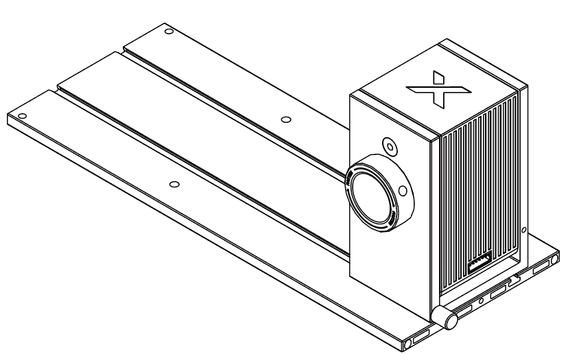
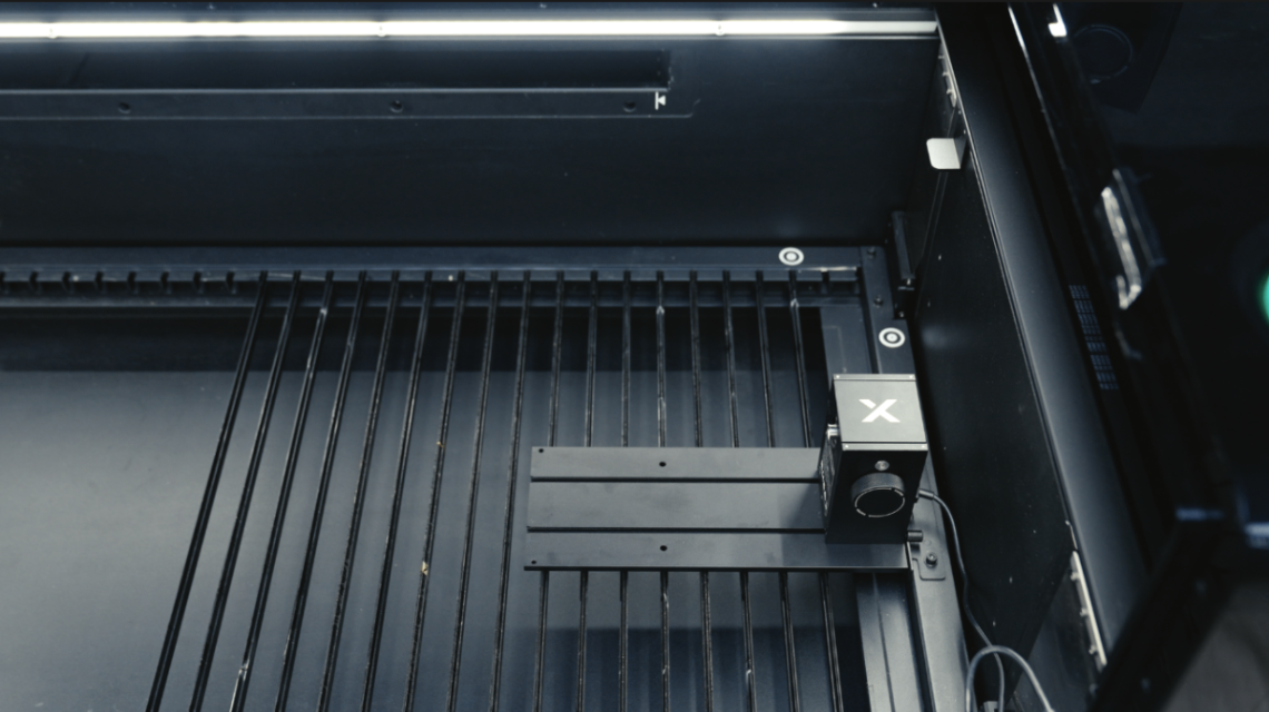
- Attach the main baseplate and the power module of RA3 to the RA3 locator inside xTool P3.
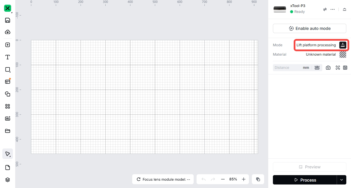
- When the mode shown on the right side of the software interface is “Lift platform processing”, “Same design – batch processing”, or “Different design – batch processing”, the software will automatically recognize RA3.
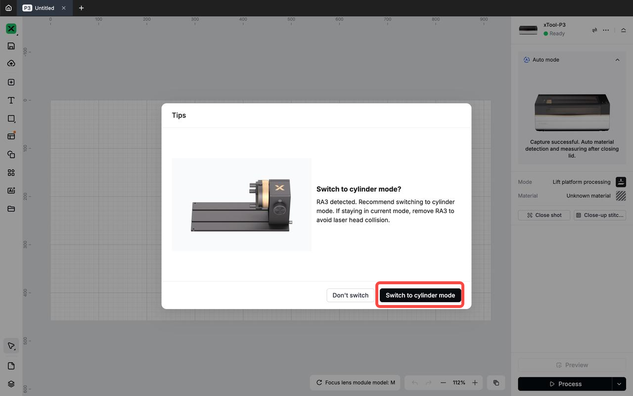
- When you close the lid of P3, the software will prompt “Switch to cylinder mode?” Select “Switch to cylinder mode”.
RA3 central axis calibration (before first use and after use for a long time)
RA3 central axis calibration is used to ensure that the design is accurately aligned with the workpiece during processing.
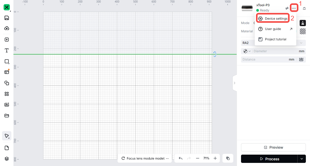
- Select the menu button (…) next to the device name and then select “Device settings”.
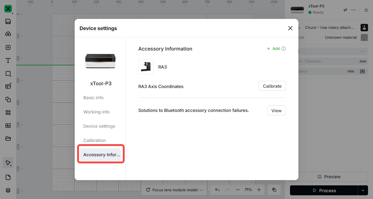
- Select "Accessory Information".
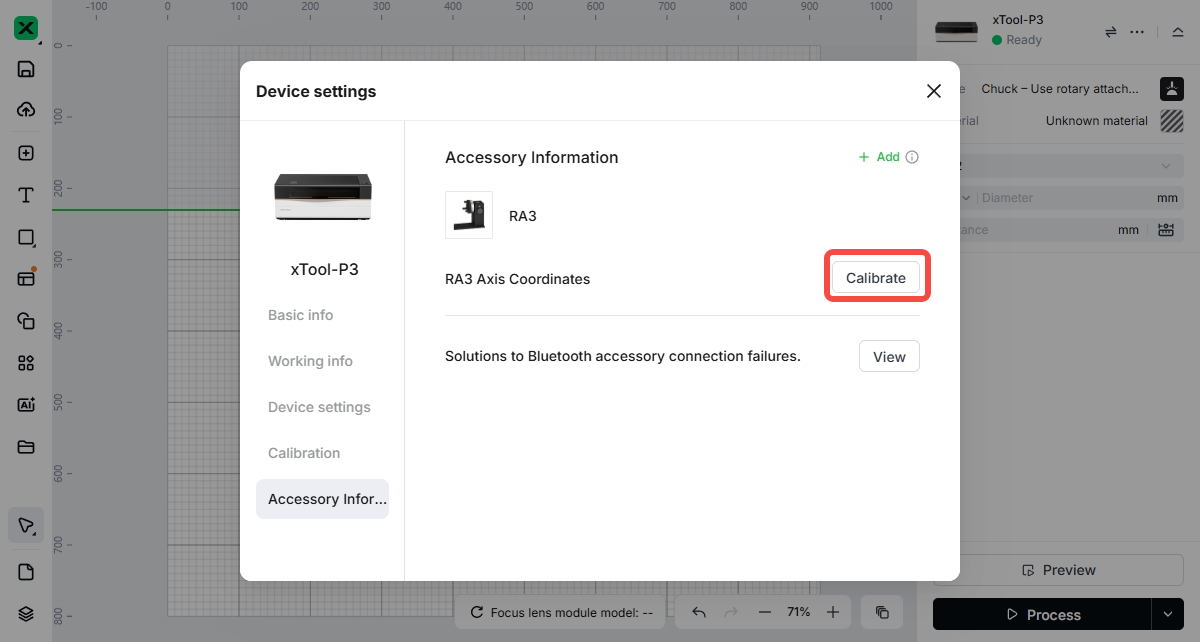
- Select "Calibrate".
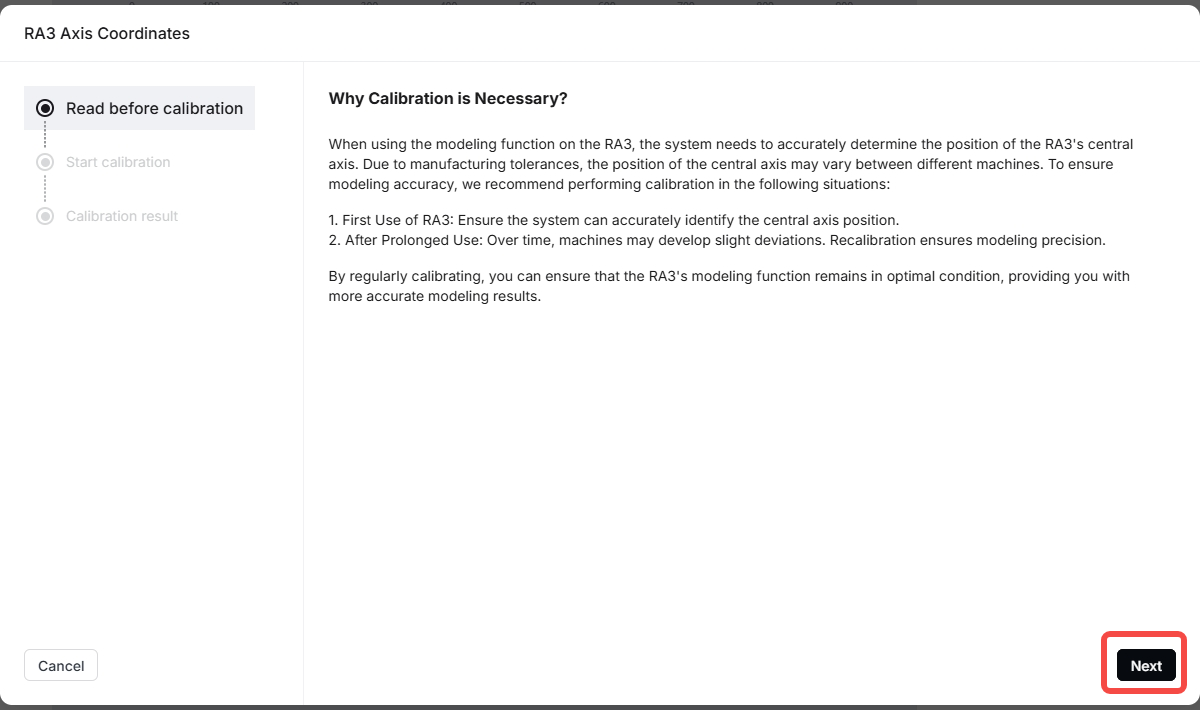
- Select "Next".
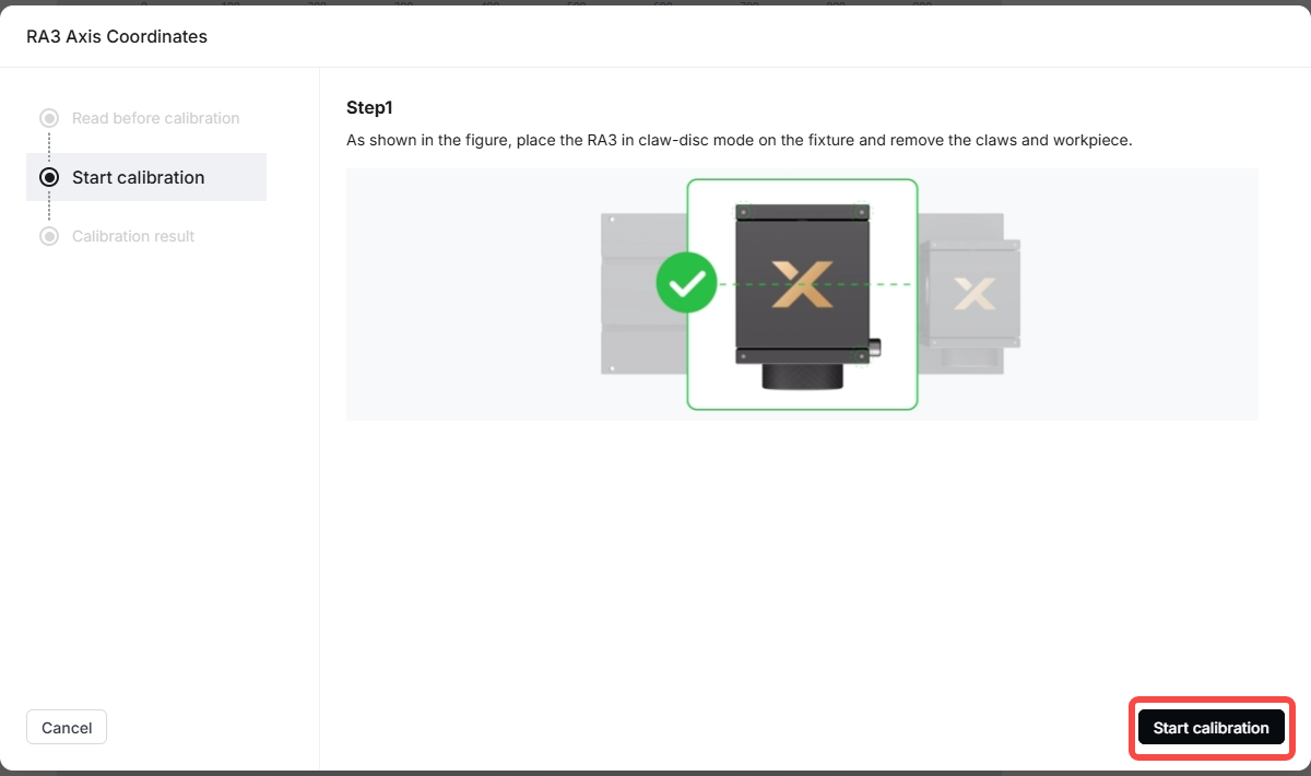
- Check whether there are jaws, the jaw chuck, or a workpiece on RA3 placed in xTool P3 (oversized workpieces may collide with the laser module). If present, remove them before performing the central axis calibration.
- Select "Start calibration".
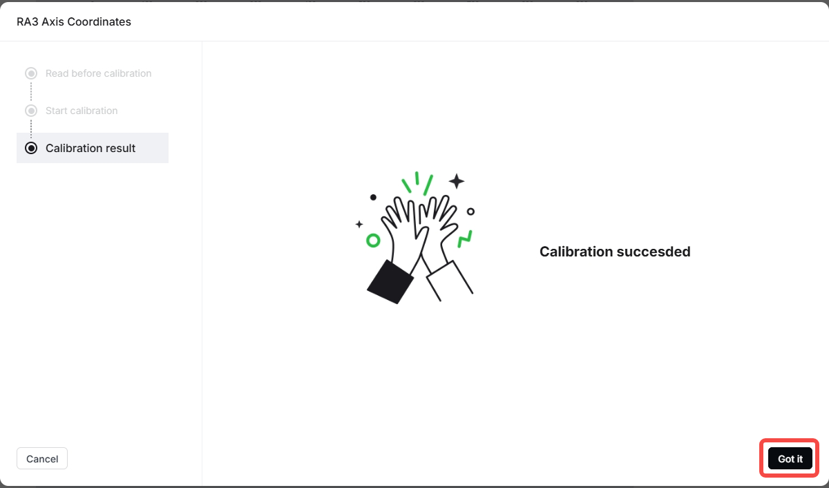
- After calibration is complete, the software will automatically go to the “Calibration result” page. Select “Got it”.
⚠️If the laser module hits a large workpiece, press the emergency stop button located at the back-right of xTool P3. After removing the workpiece, release the emergency stop button and perform the central axis calibration again.
Select the material
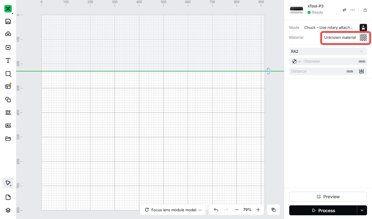
- Select "Unknown material".
- Select "Search Materials".
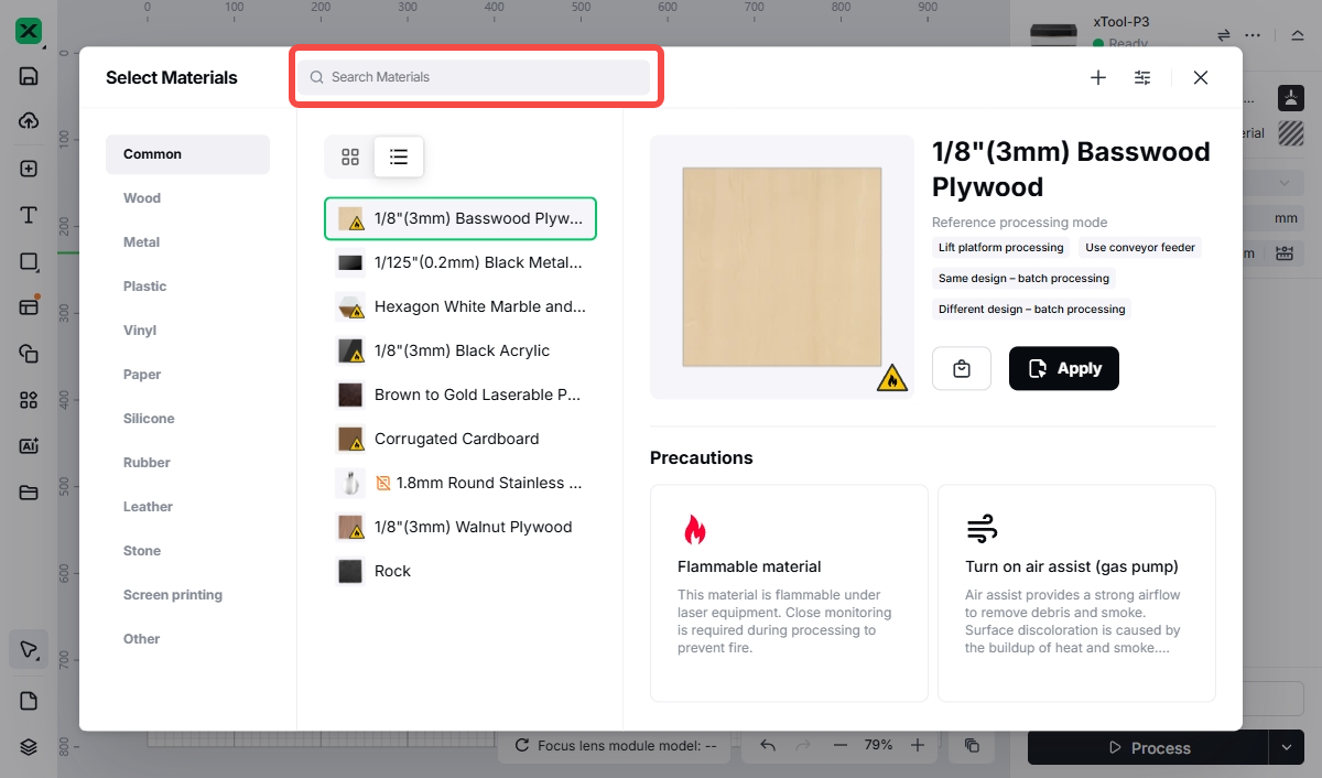
- Enter keywords to search, for example, “tumbler”.
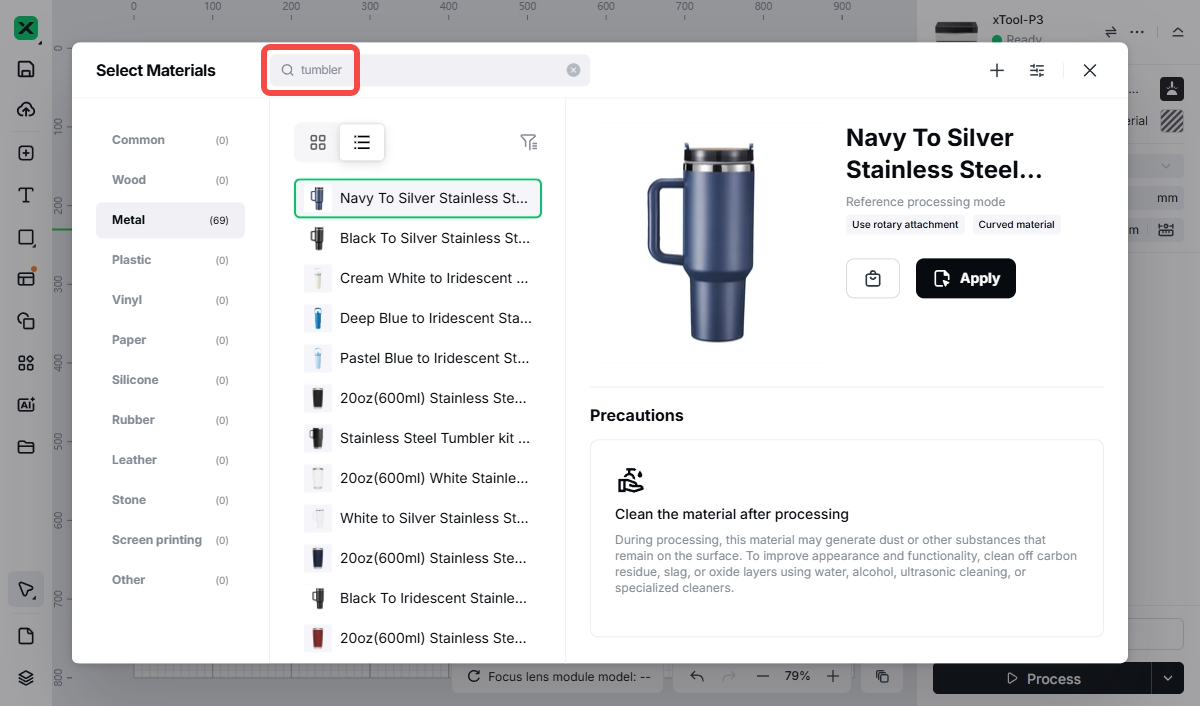
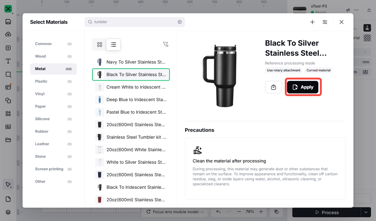
- Under the “Metal” tab, select the tumbler style and then select “Apply”.
Modeling
Standard modeling
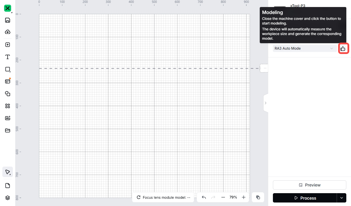
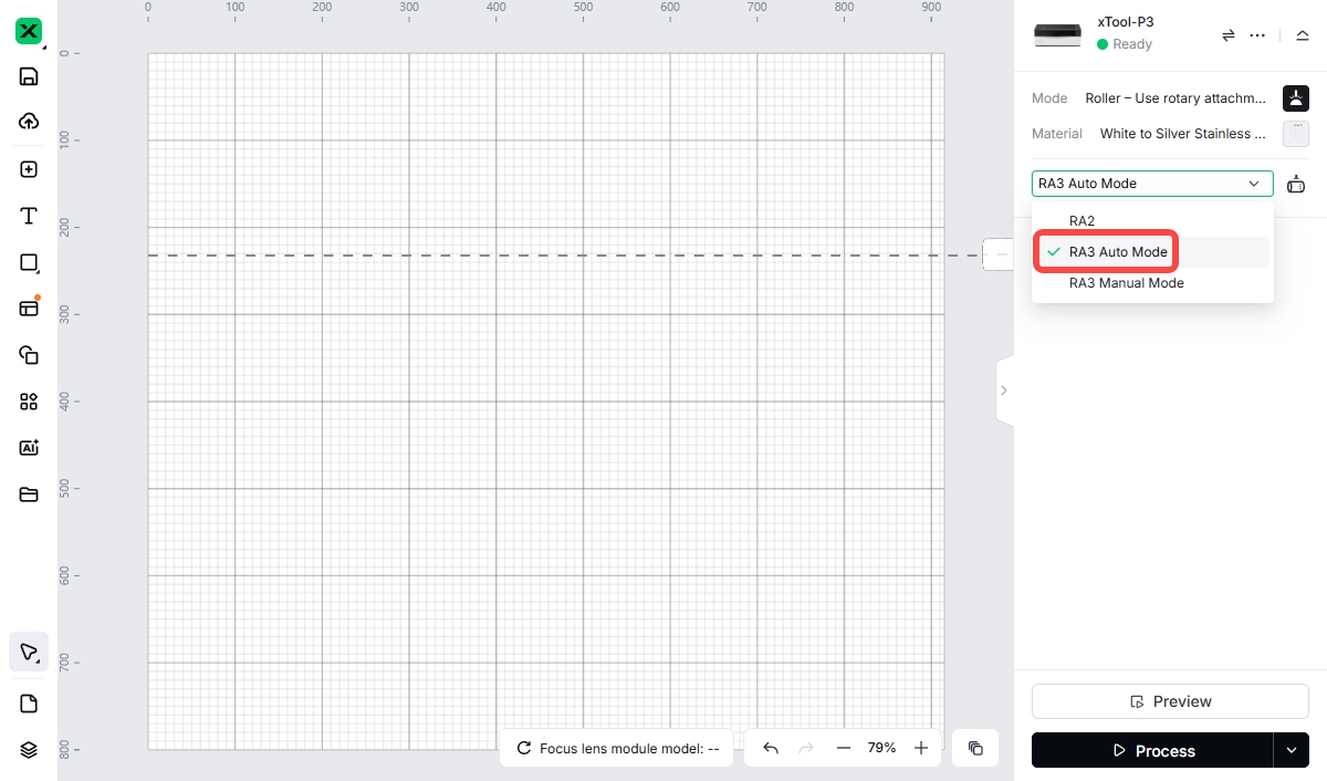
- From the dropdown menu under “Material”, select “RA3 Auto Mode”.

- Select the modeling button.
- Follow the instructions in the pop-up window: place the material, ensure the handle is oriented correctly, and then select “Quick modeling”.
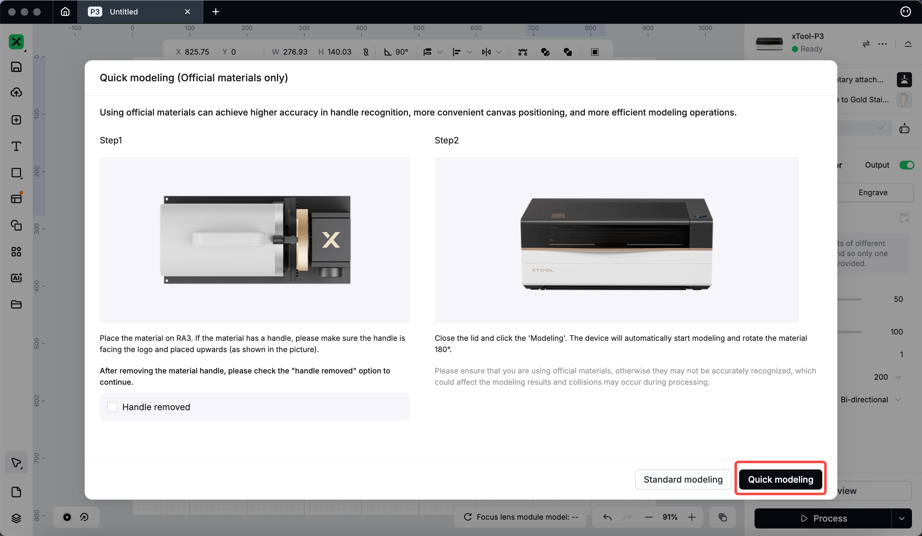
💡You can also choose to remove the tumbler handle and place the tumbler back onto the jaw chuck components. In the software interface, check “Handle removed”, and then select “Quick modeling”. In quick modeling mode, the system only detects the starting point.
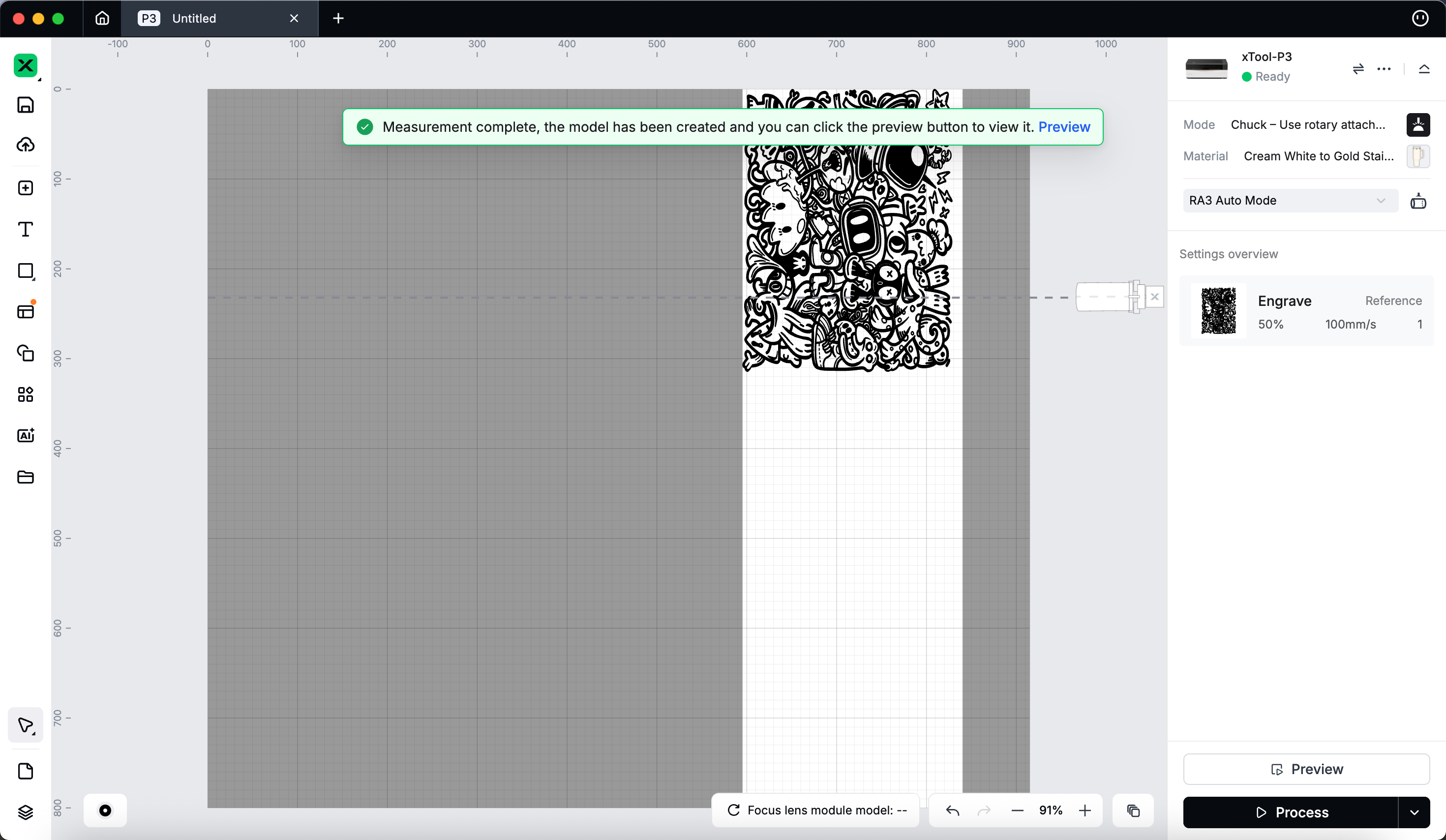
- After modeling is complete, the system will prompt “Measurement complete…”. The white area indicates the workable area, while the gray area indicates the non-workable area. Add processing elements (patterns or text) within the white area.
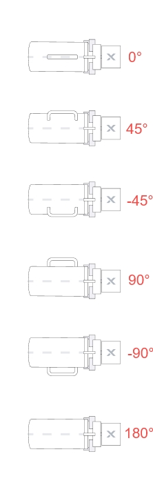
The RA3 icons in the software interface represent different surfaces, and the dashed lines above the icons indicate the central axis of the workpiece.
- A handled cup is shown in the image below. "0°" indicates the cup handle is facing directly upward, "45°" indicates the cup handle has been rotated 45 degrees clockwise, "-45°" indicates the cup handle has been rotated 45 degrees counterclockwise, "90°" indicates the cup handle has been rotated 90 degrees clockwise, "-90°" indicates the cup handle has been rotated 90 degrees counterclockwise, and "180°" indicates the cup handle has been rotated 180 degrees clockwise or counterclockwise.
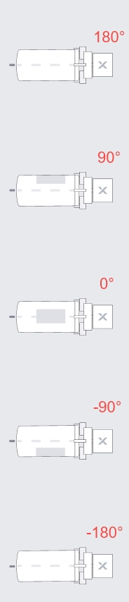
- A cup without a handle is shown in the image below. "0°" indicates the front of the cup is facing directly upward, "180°" indicates the cup has been rotated 180 degrees clockwise, "90°" indicates the cup has been rotated 90 degrees clockwise, "-90°" indicates the cup has been rotated 90 degrees counterclockwise, and "-180°" indicates the cup has been rotated 180 degrees counterclockwise.
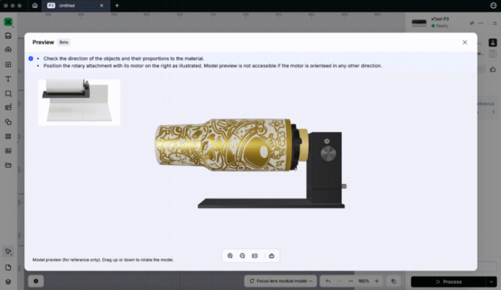
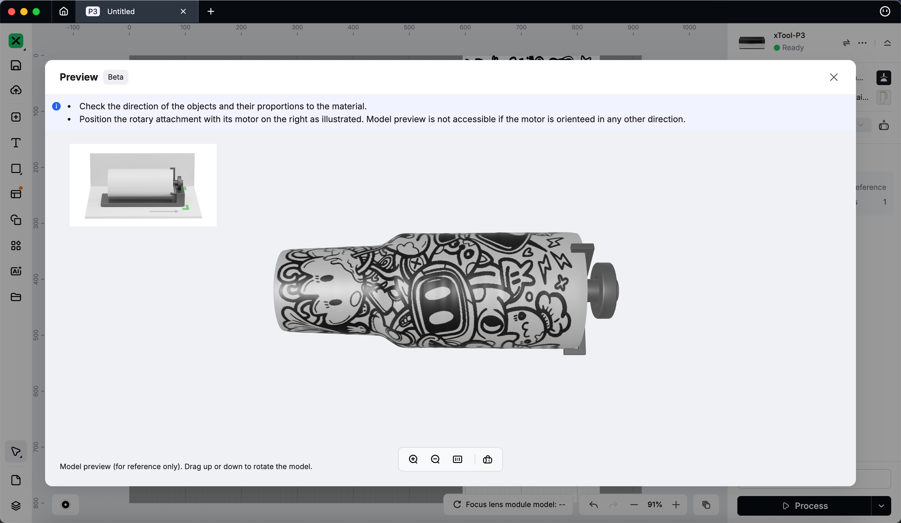
- Select “Preview” at the bottom-right corner of the software interface to see how the processing elements will appear on the workpiece. You can use the left mouse button to click and drag the workpiece to speed up the preview display.
Standard modeling (for non-official materials)
- If you are not using official materials, select the modeling button.
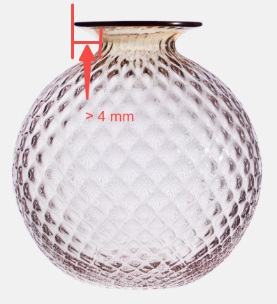
When using "RA3 Auto Mode", avoid processing reflective materials or materials with a height difference exceeding 4 mm (such as the bottle shown in the image below), as this may lead to recognition or modeling failure. For reflective materials, it is recommended to choose "RA3 Manual Mode".
- After modeling is complete, the system will prompt “Measurement complete…”. The white area indicates the workable area, while the gray area indicates the non-workable area. Add processing elements (patterns or text) within the white area.
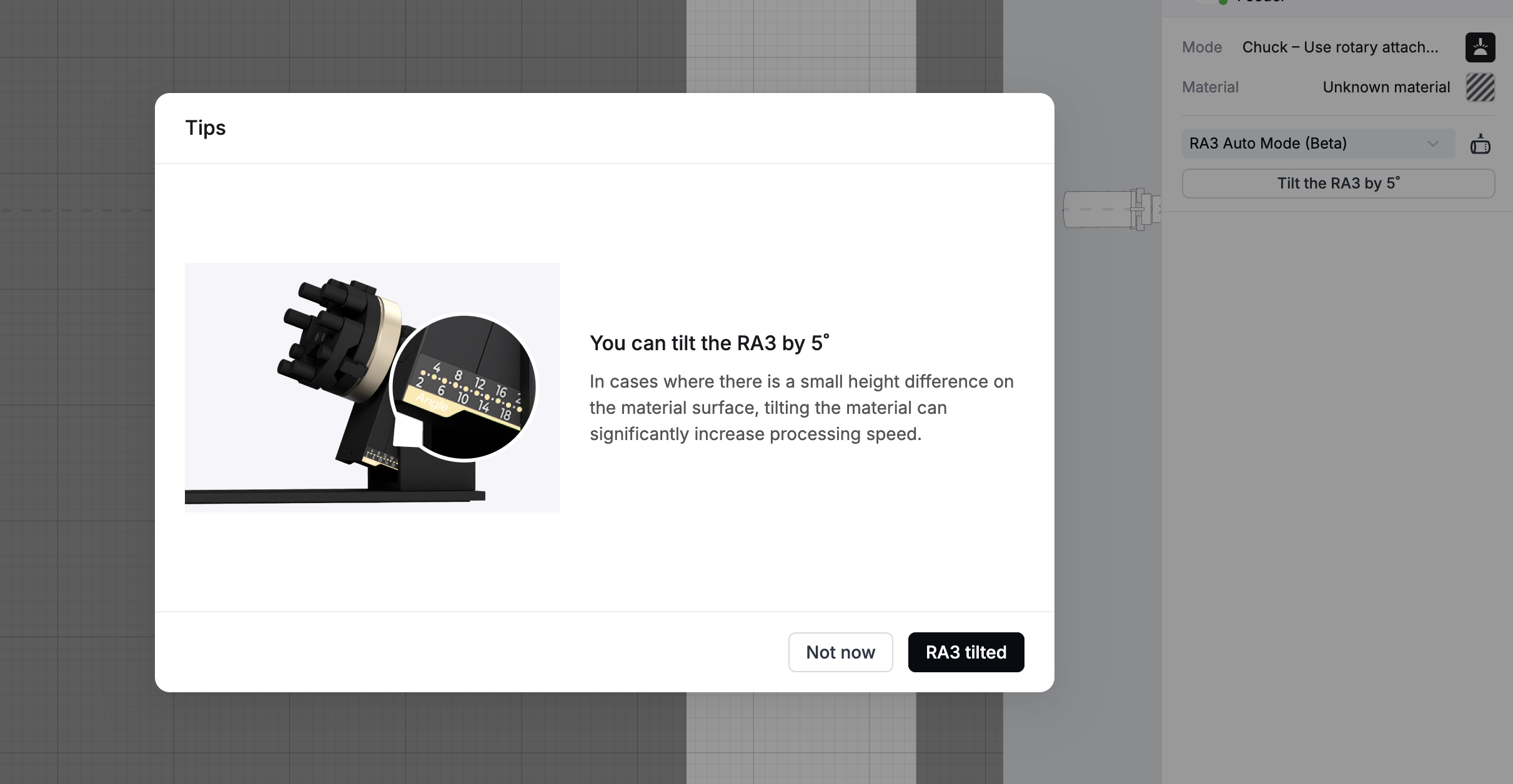
- In certain scenarios, a tilted prompt window may appear. At this time, you can tilt the entire material to the angle indicated by the software. Doing so will significantly increase the machine’s processing speed compared to non-lifting scenarios, and the processing time can be reduced by more than 60%.
- Select “Preview” in the bottom-right corner of the software interface to see how the processing elements will appear on the workpiece. You can use the left mouse button to click and drag the workpiece to speed up the preview display.
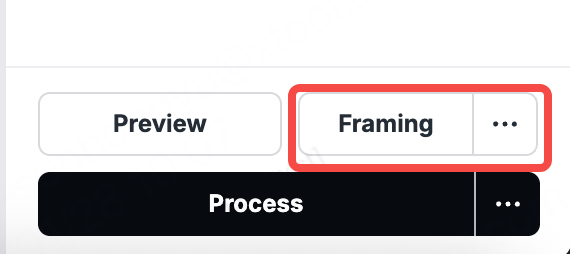
- Use the “Framing” button in the bottom-right corner of the software interface to view the corresponding position for engraving.
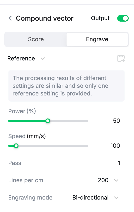
Set processing parameters
Set the power, speed, pass, lines per cm, engraving mode, and other parameters in the panel on the right side of the software interface.
Start processing
- Check whether the workpiece is securely positioned.
- Select “Process” to go to the "Check before processing" page and pay attention to the prompts. Then select "Start".
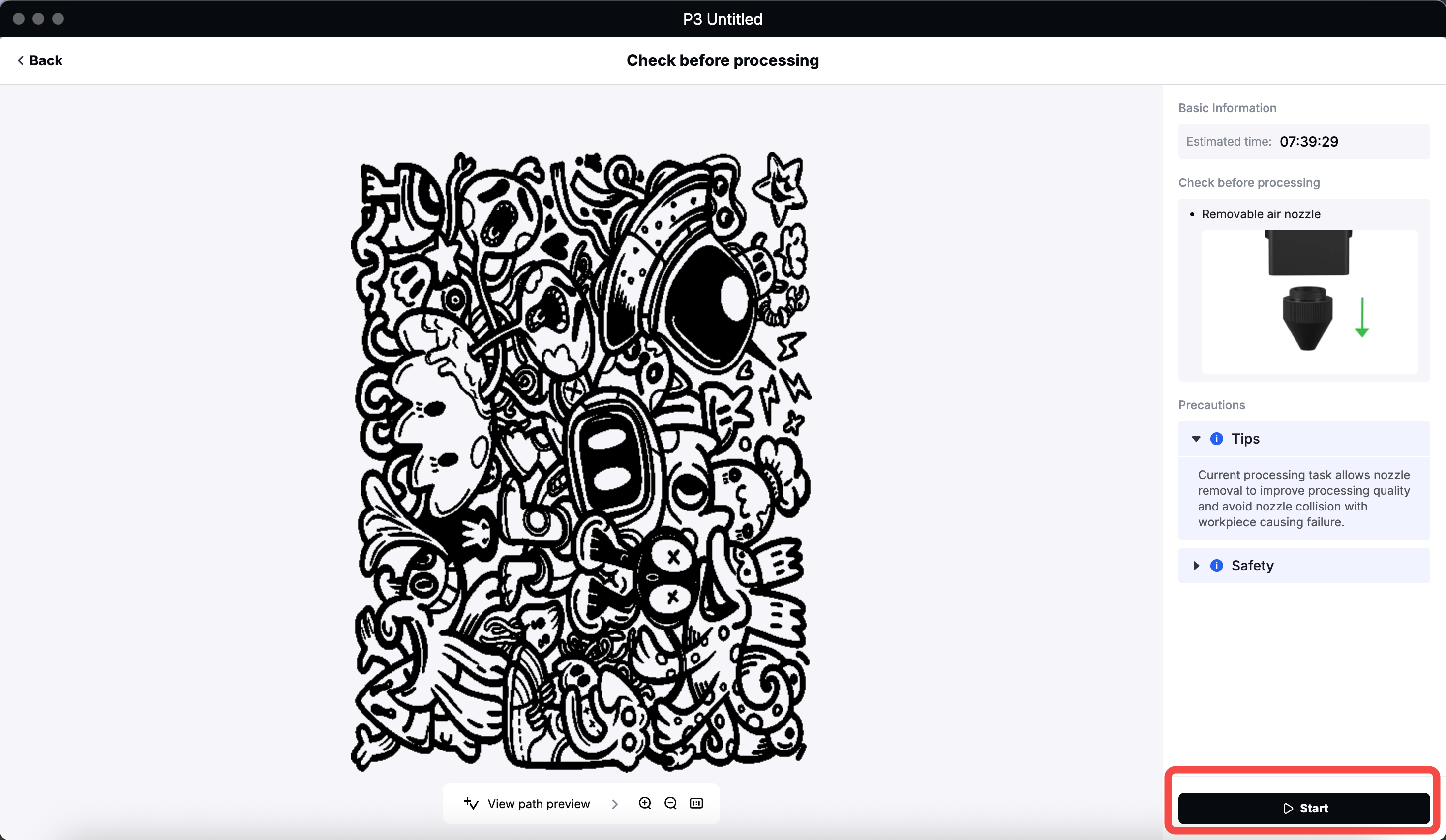
💡After selecting “Process”, select “Start” in the “Check befor processing” pop-up window. If the power value is too low (for example, 1%), selecting “Process” may trigger a warning. Increasing the power will prevent this warning from appearing. If the nozzle on the laser module of xTool P3 has not been removed earlier, it can be removed at this time.
- Press the control knob on xTool P3 to start processing.
Differences in roller mode
When RA3 is assembled in roller mode, the following differences apply.
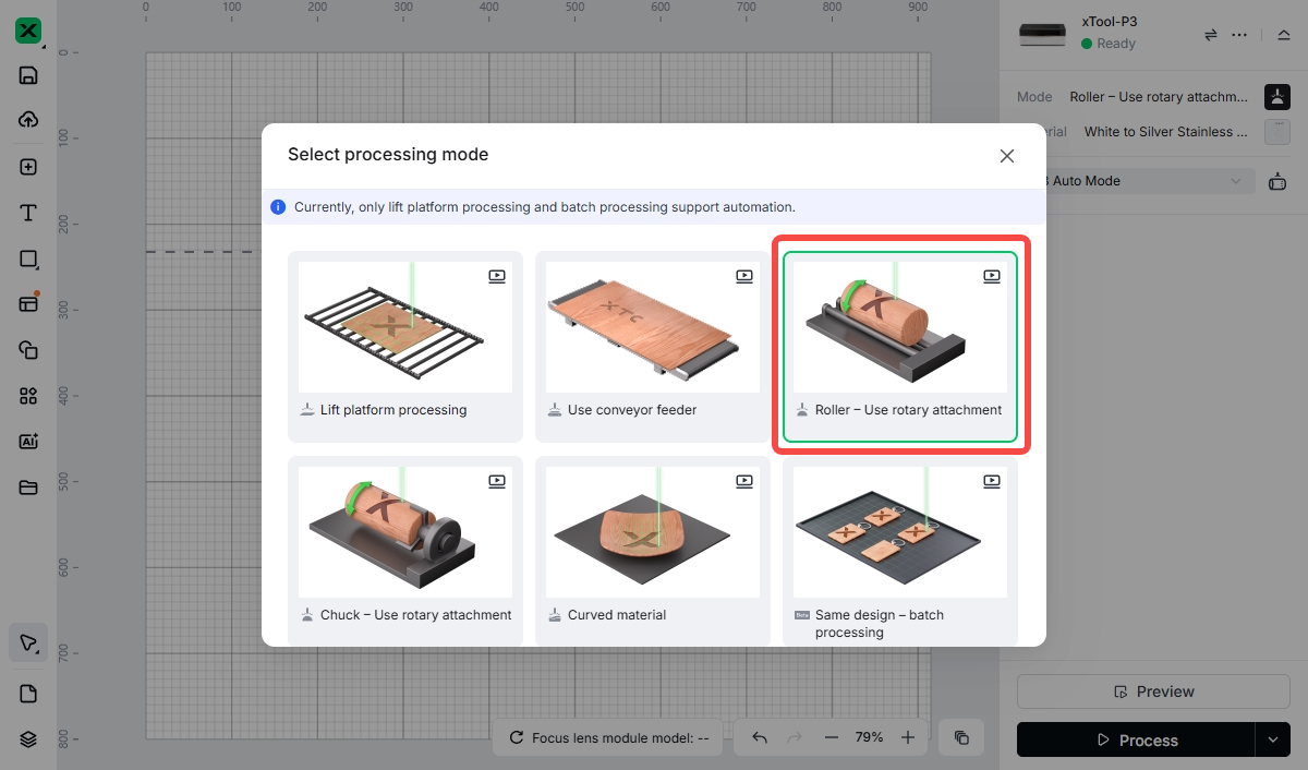
- Select “Roller – Use rotary attachment” on the “Select processing mode” pop-up window.
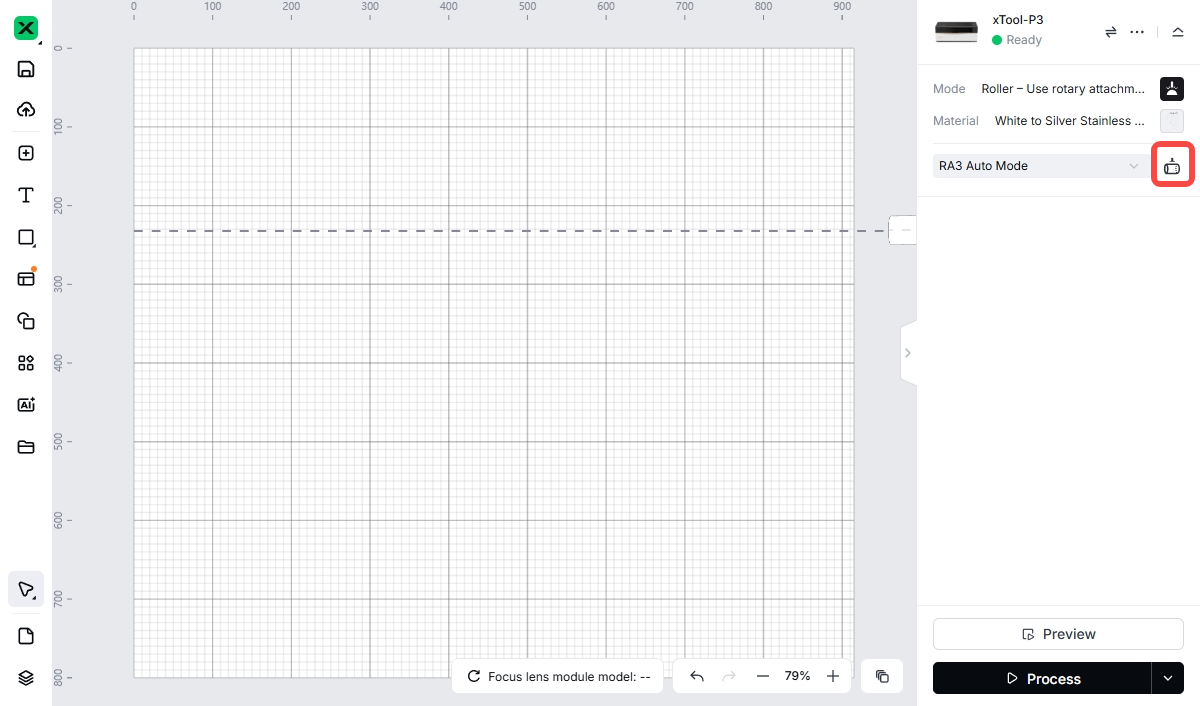
- From the dropdown menu under “Material”, select “RA3 Auto Mode”.
- Select the modeling button on the right (make sure the lid of xTool P3 is open).
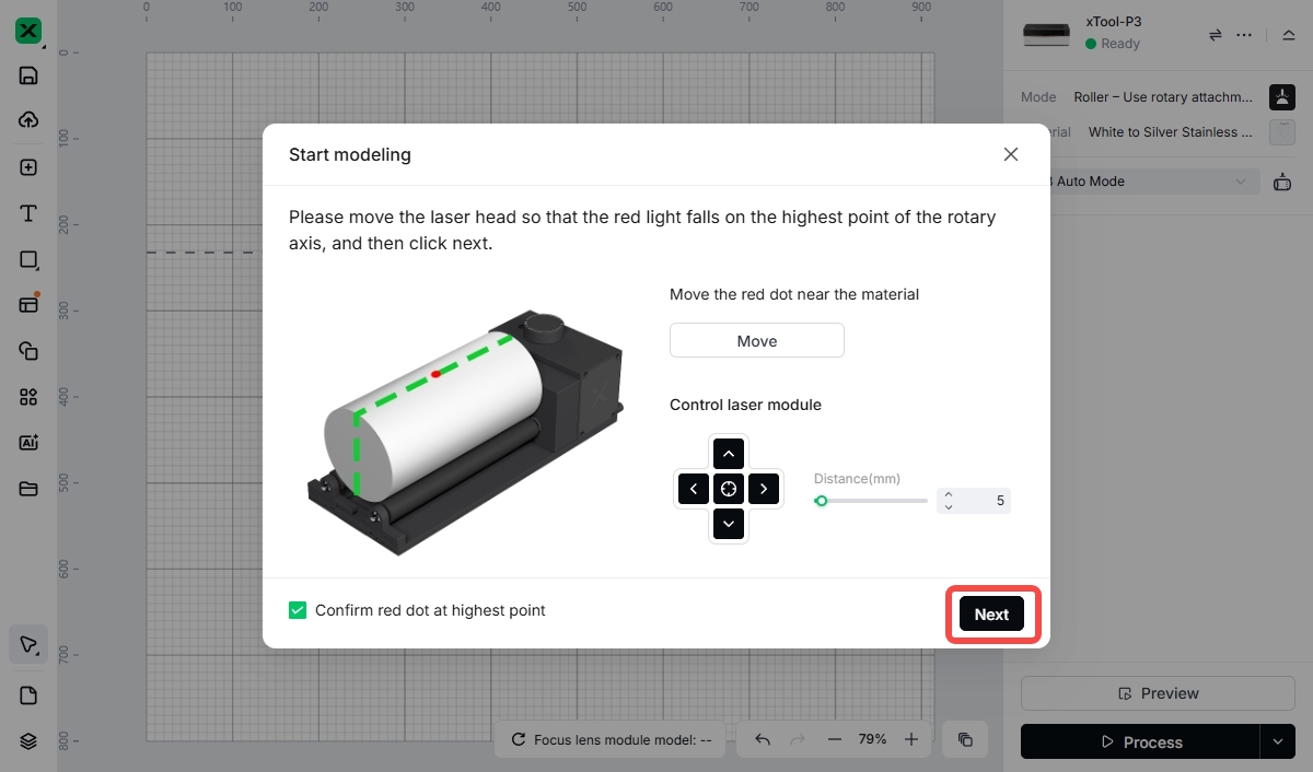
- Select "Move" on the “Start modeling” pop-up window.
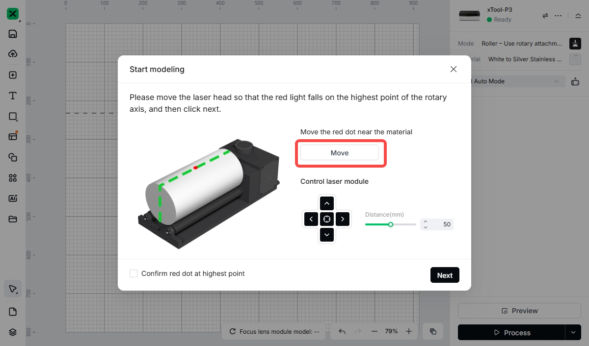
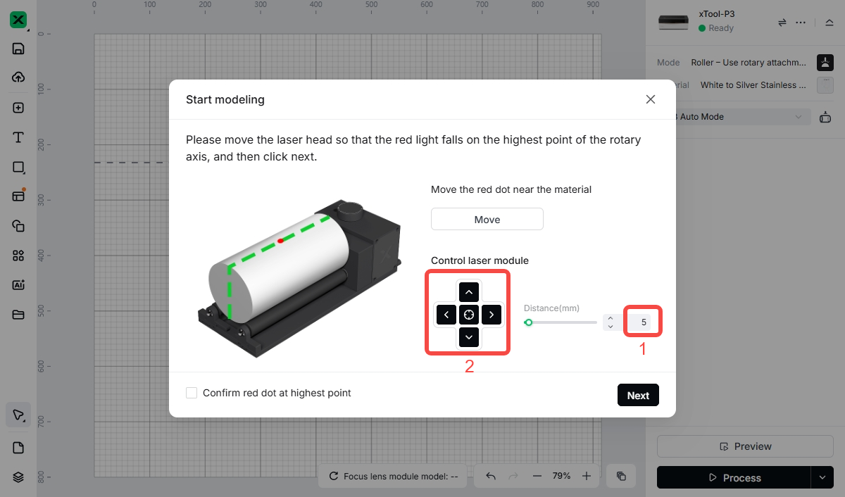
💡If the red dot is not at the highest point of the workpiece’s central axis, enter a value (for example, 5) in “Distance(mm)” and use the Up/Down/Left/Right buttons for fine adjustment.
- Once the red dot is at the highest point, check “Confirm red dot at highest point”.
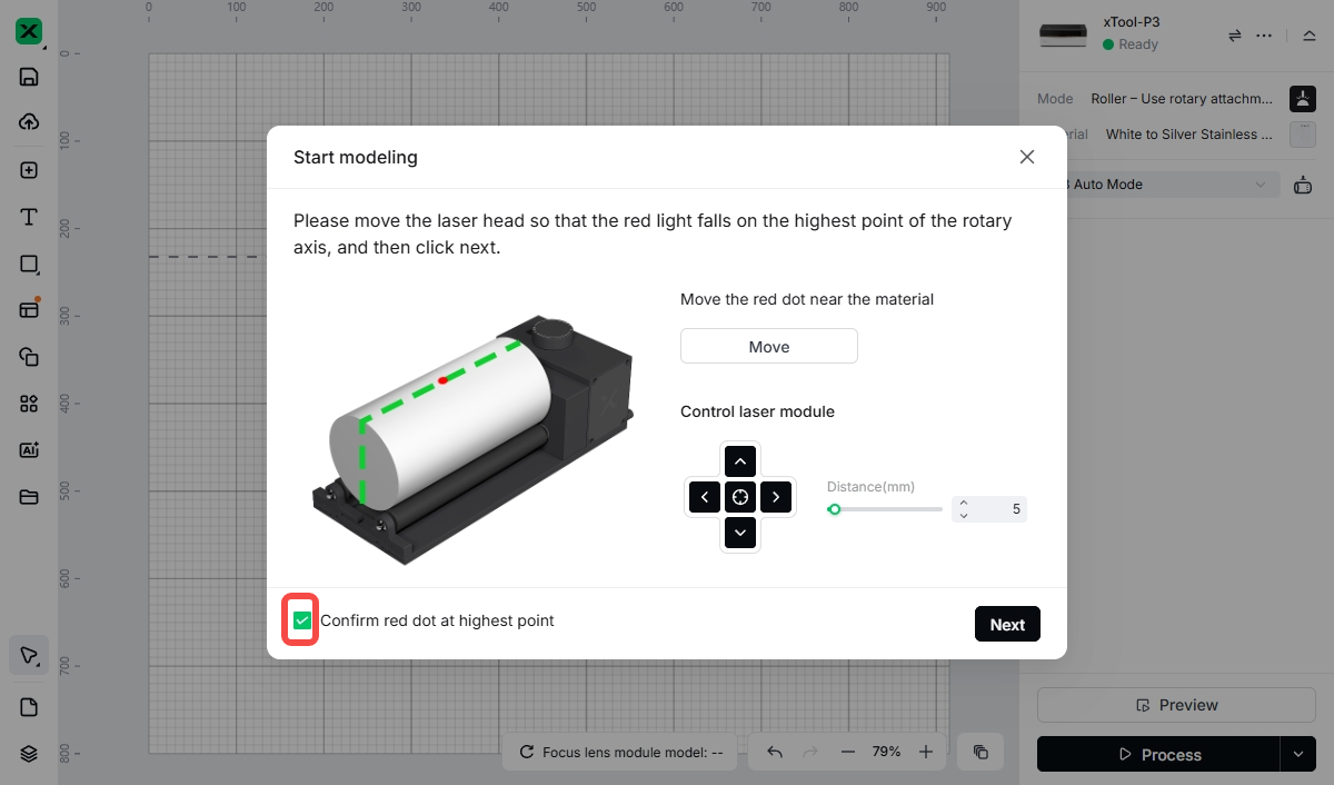
- Select "Next". The laser module will automatically measure the diameter and height of the cylinder.
Differences in manual mode
When using manual mode as the processing mode, the following differences apply (using jaw chuck mode as an example).
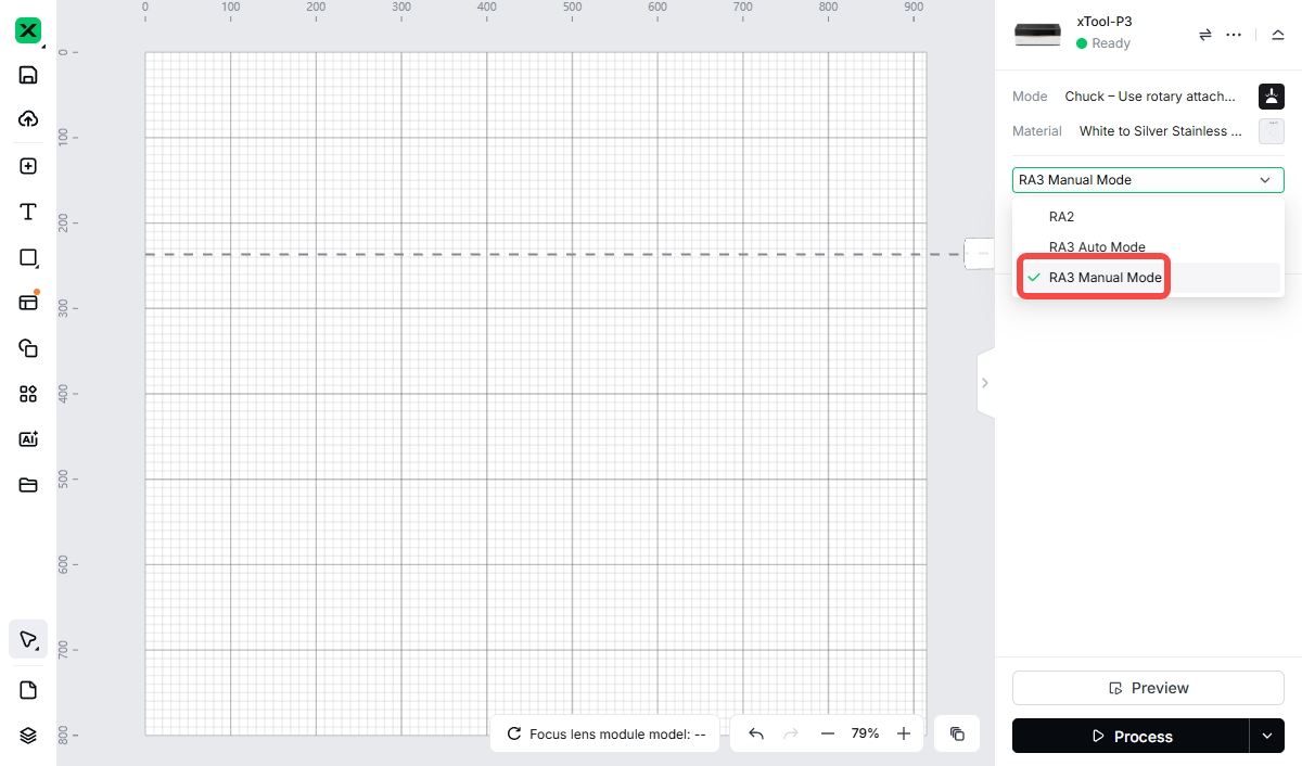
- From the dropdown menu under “Material”, select “RA3 Manual Mode”.
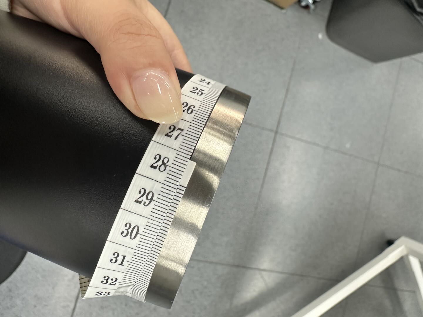
- After measuring the diameter or perimeter of the workpiece with a caliper or tape measure, enter the measured value into the software interface.
- Click the precision measurement icon below the diameter/perimeter value.
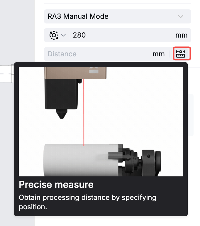
- Select "Move" on the "Aimed-measure" pop-up window.
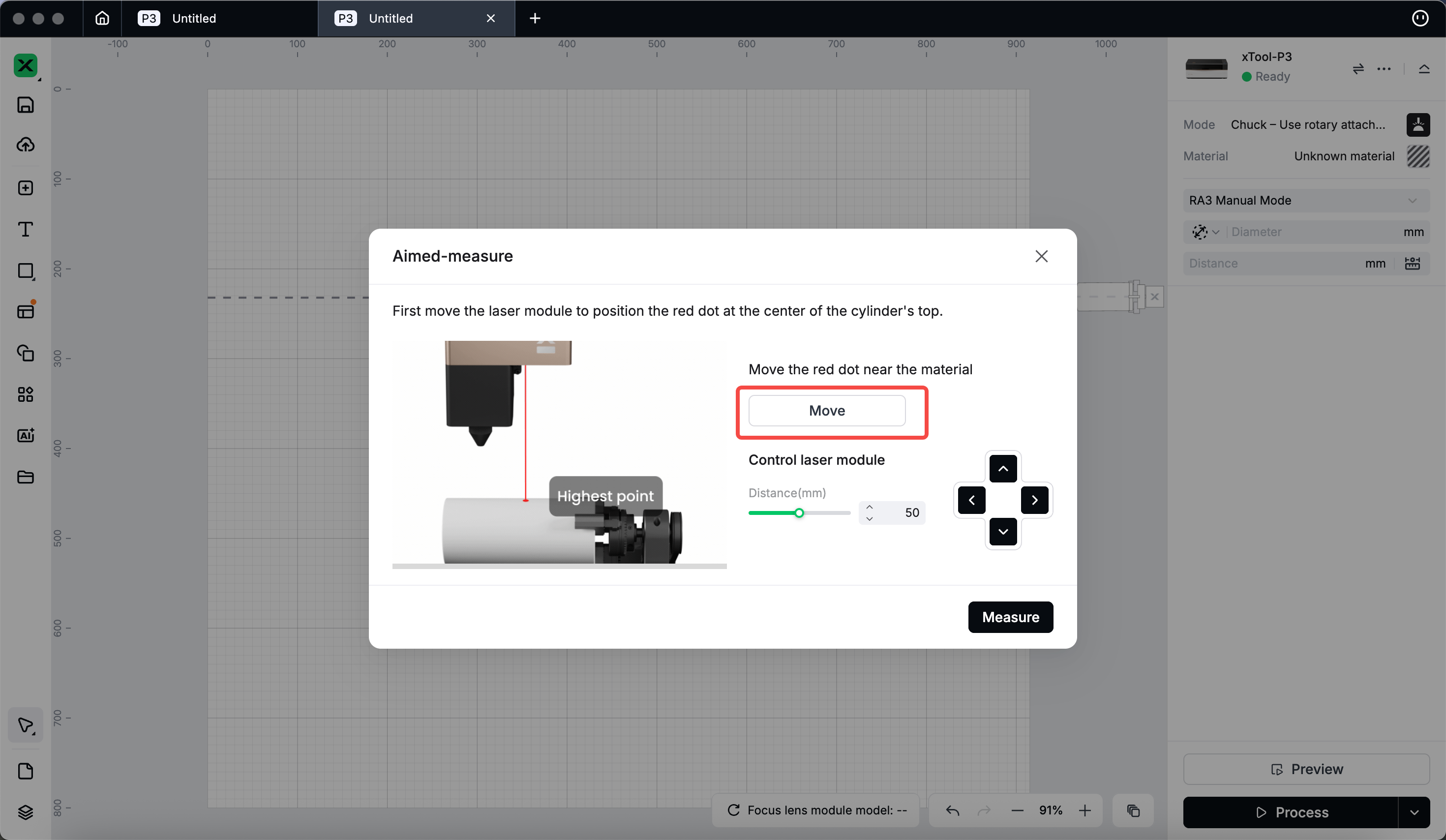
💡If the red dot is not at the highest point of the workpiece’s central axis, enter a value (for example, 5) in “Distance(mm)” and use the Up/Down/Left/Right buttons for fine adjustment.
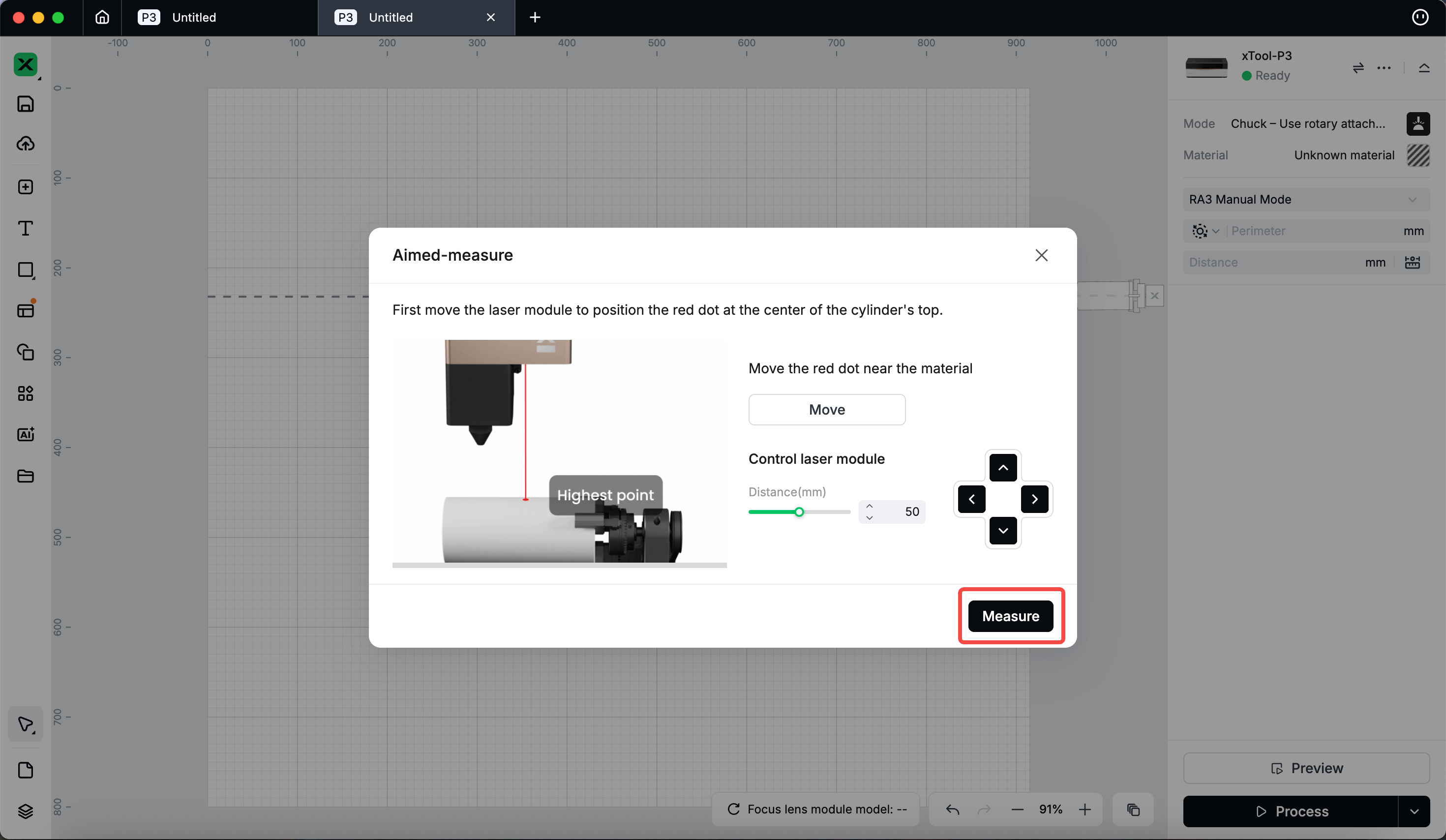
- Once the red dot is at the highest point, select “Measure”. The system will automatically fill the measured distance into the distance field.
More information about key components of RA3
Functions
Part name | Image | Function |
|---|---|---|
Height-extension module | Raising the jaw chuck components allows processing of larger workpieces. | |
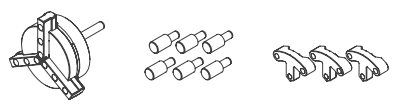
Roller components | Suitable for processing slender, easily rolling workpieces (for example, pens and chopsticks); non-slip surface with adjustable roller spacing. | |
Holder for roller components | Secures the roller components, ensuring the workpiece remains accurately positioned during processing. | |
Support module | Secures the workpiece. | |
Mini level | Ensures the workpiece surface is level to prevent engraving tilt. | |
Tape measure | Measures workpiece perimeter or diameter for parameter setup and clamp adjustment. |
Use and maintenance recommendations
Part name | Image | Recommendation |
|---|---|---|
Jaw chuck components |
| Depending on the size and shape of the workpiece, you can choose to use only the cylindrical jaws or both the T-shaped and cylindrical jaws. After clamping the workpiece, ensure it is securely held. When replacing the jaw chuck, always power off the machine and make sure the jaw chuck is properly fastened to prevent the workpiece from loosening or falling during processing. |
Roller components | During installation, keep the rollers parallel to the workpiece contact surface and regularly clean the roller surfaces to prevent dust from affecting clamping force. | |
Height-extension module | After height adjustment, ensure all screws are tightened to prevent movement during processing. | |
Mini level | Recalibrate the level after changing workpieces or moving RA3. | |
Connection cable | Ensure correct connector orientation when plugging or unplugging to avoid damaging the pins. It is recommended to regularly check whether the cables are loose or worn, and replace them if necessary. |
Common issues and solutions
Issue | Solution |
|---|---|
Workpiece not securely clamped | Check whether the jaw chuck or rollers are properly installed and adjust the clamping force as needed. |
Uneven rotation | Check whether the roller transmission module and the holder for roller components are secure, and clean any debris from the roller surfaces. |
Tilted engraving | Recalibrate using the mini level to ensure the workpiece surface is level. |
Power or signal interruption | Check if the connector of the connection cable is loose and replace the connection cable if necessary. |
