Note: xTool MetalFab Laser Welder 1200W and xTool MetalFab Laser Welder 800W have slightly different touchscreen interfaces, which will be noted in this article. |
Overview
Standard mode |
|
Advanced mode |
|
Technique library |
|
Machine status |
|
System settings |
|
Wire feeder (For 1200W) |
|
Wire control (For 800W) |
|
Safety interlock loop |
|
Parameter setting modes
You can set processing parameters under different modes.
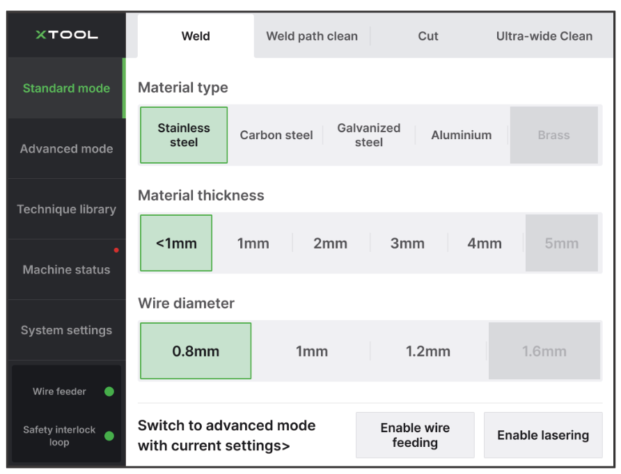
Standard mode
In this mode, you only need to select the processing mode and material properties (and wire properties for welding). Based on your selection, the machine will apply recommended parameter settings for processing.
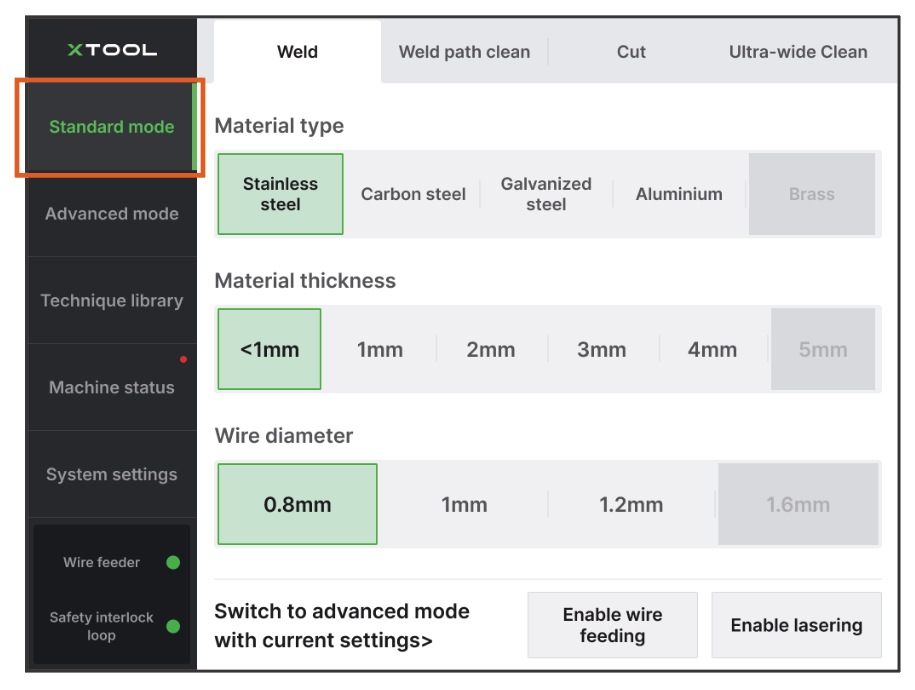
To enter the standard mode, tap Standard mode on the left of the touchscreen.
Note: For more information about each processing mode, see Processing Modes Explained. |
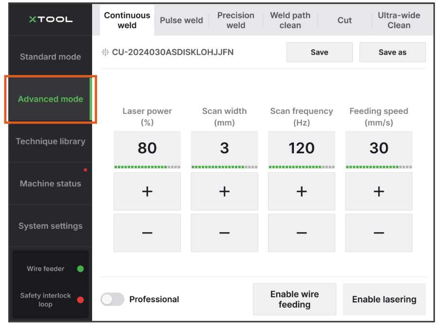
Advanced mode
In this mode, you can access more welding modes and adjust basic processing parameters. You can also save your settings to the technique library for future use.
To enter the advanced mode, take one of the following methods:
- Tap Advanced mode on the left of the touchscreen.
- Go to Standard mode first. Select processing mode, material properties (and wire properties for welding). Then, in the bottom left corner, tap Switch to advanced mode with current settings.
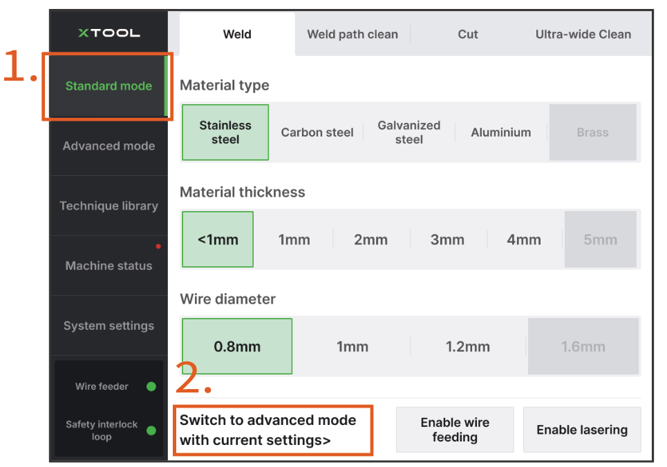
Tips: By switching to advanced mode from standard mode, the system will display the recommended parameter settings based on your selections under standard mode. You can fine-tune the recommended settings instead of performing testing from scratch. |
Note: For more information about each processing mode, see Processing Modes Explained. For more information about each processing mode, see How to Choose Welding Parameters? |
Professional mode
In this mode, you can have full control over all processing parameters.
To enter the professional mode, enter Advanced mode first. Then, in the bottom left corner, turn on Professional.
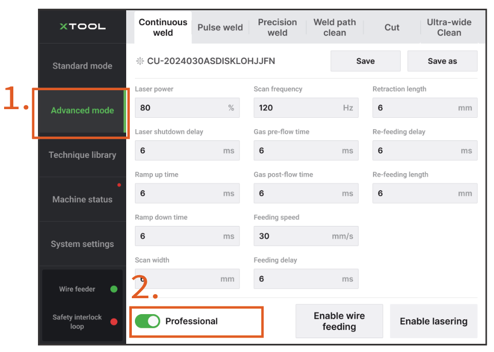
Note: For more information about each processing mode, see Processing Modes Explained. For more information about each processing mode, see How to Choose Welding Parameters? |
Save settings to Technique library
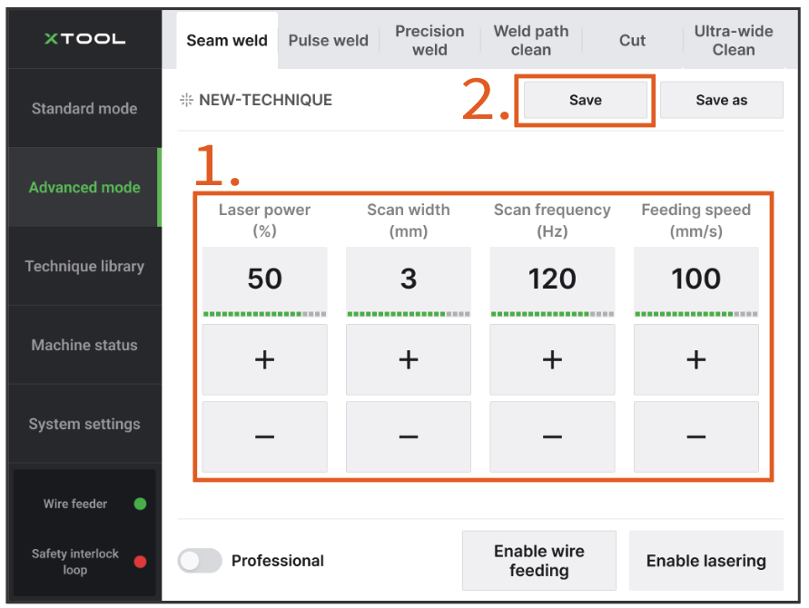
Save parameter settings
In Advanced mode (or Professional mode), set a proper value for each parameter. Then, tap Save as > input a name for the new technique > tap Confirm.
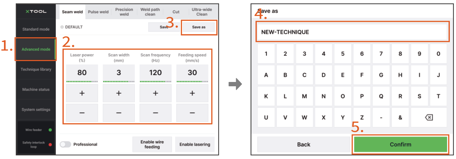
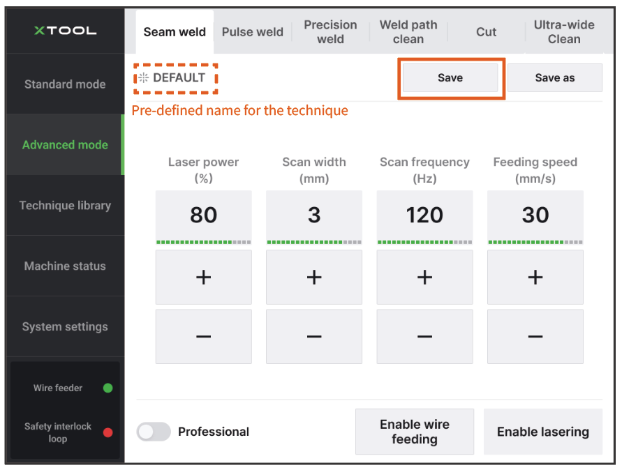
Note: You can also tap Save to save the current settings with the predefined name.
|
Apply saved settings
In Technique library, select the processing mode, tap the technique name, and then tap Apply. The system will switch to the Advanced mode with the technique settings.
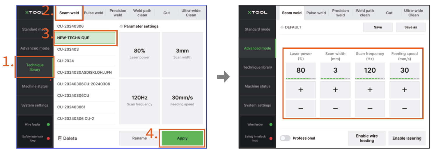
Modify settings for a technique
(1) In Technique library, select the technique you want to edit, and then tap Apply. The system will switch to the Advanced mode with the technique settings.
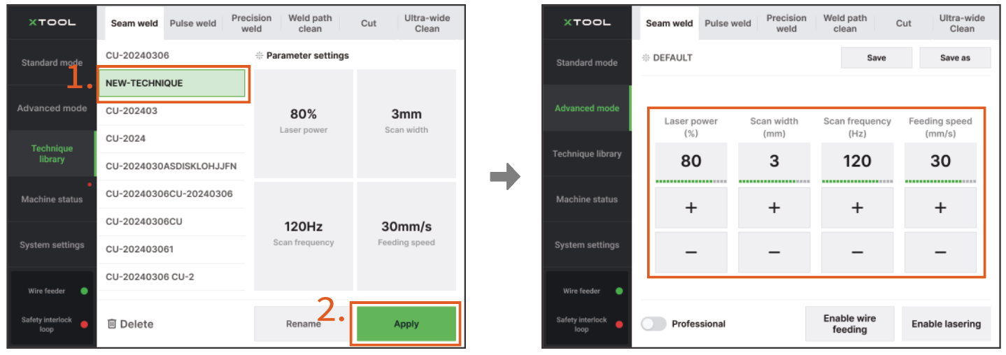
(2) Modify the parameter settings, and then tap Save. The new settings will be updated to the technique.
Machine status
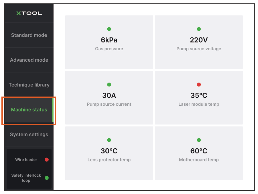
- Gas pressure: The pressure of the supplied shielding gas.
Note:
|
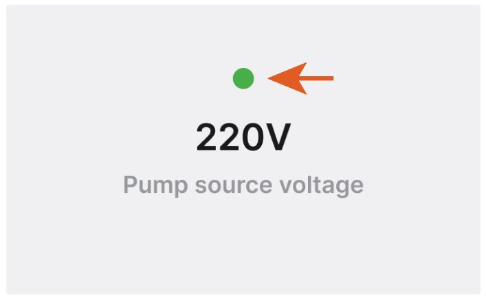
- Pump source voltage: The voltage supplied to the laser pump.
- Pump source current: The current supplied to the laser pump.
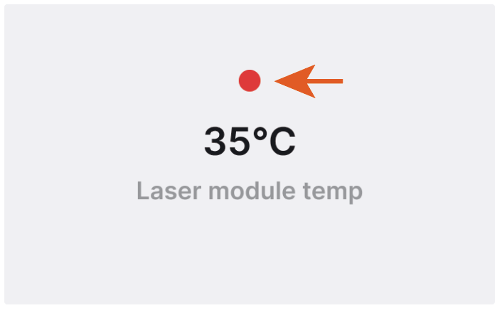
- Laser module temp: The temperature of the laser module (which is inside the main unit).
- Lens protector temp: The temperature of the laser lens protector (which is inside the welding head).
- Motherboard temp: The temperature of the motherboard, the central circuit board in the device.
Note:
|
System settings
Machine information
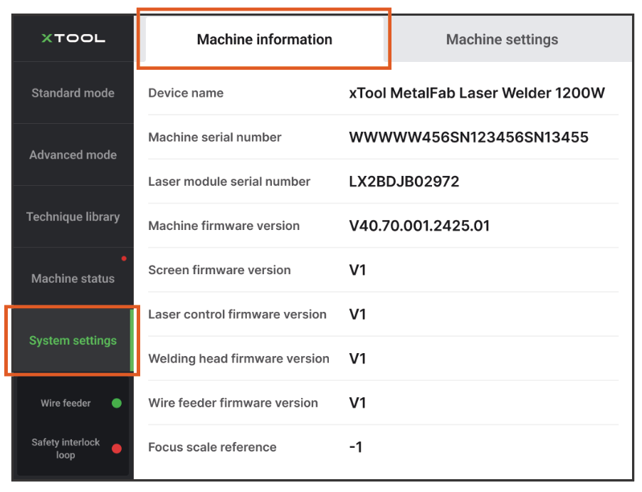
In Machine information, you can view the following information:
- Device name
- Machine serial number
- Laser module serial number
- Machine firmware version
- Screen firmware version
- Laser control firmware version
- Welding head firmware version
- Wire feeder firmware version
- Focus scale reference
Note: Ensure that the scale of the graduated tube on the welding head matches the Focus scale reference displayed on the touchscreen. |
Machine settings
In Machine settings, you can select a language and unit for the system.
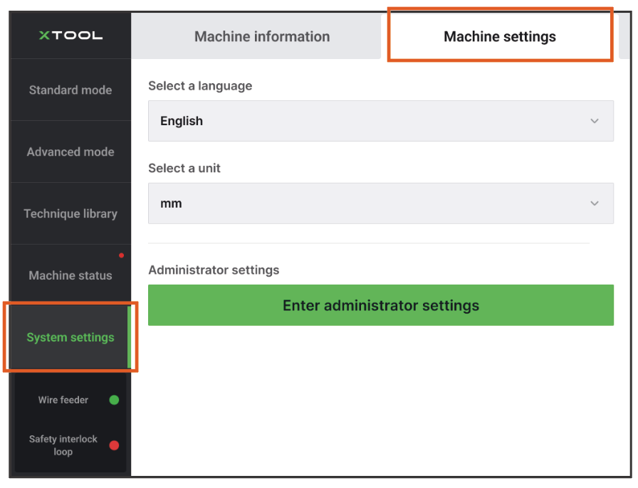
Caution: Administrator settings should be modified ONLY under the instruction of xTool technical support. Improper modification may lead to machine damage. |
Wire feeder (For 1200W)
Check the connection status of the wire feeder at the bottom left corner of the screen.
A green dot indicates that the wire feeder is properly connected.

A red dot indicates that the wire feeder is disconnected.

Note: For more information on how to install and connect the wire feeder, see How to Install and Set the Wire Feeder? |
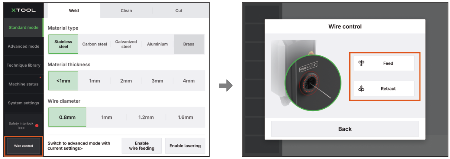
Wire control (For 800W)
Control the wire feeding system to feed or retract wire.
In the bottom left corner of the screen, tap Wire control. Then, use the Feed and Retract buttons to move the wire.
Safety interlock loop
Check the connection status of the safety interlock loop at the bottom left corner of the screen.
A green dot indicates that the safety interlock loop is closed.

A red dot indicates that the safety interlock loop is not closed.

Note: A safety interlock loop exists between the welding head, the workpiece, and the main unit of the machine. When the workpiece sensing cable connects the main unit with the workpiece and the welding head is in contact with the workpiece, the safety interlock loop is closed. |
