Issue description
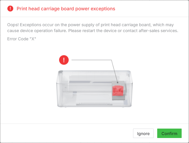
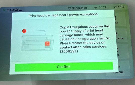
While you are using your xTool Apparel Printer, an error message may appear in xTool Studio, xTool Creative Space (XCS) software, or on the printer's LCD control panel stating "print head carriage board power exceptions".
- Please refer to this content for troubleshooting.
Note: The error code displayed with this message will be a string of numbers (e.g., "2047987") rather than the letter "X" shown in this reference image.
Potential causes
- The printer's power cord was plugged in and out too quickly.
- The print head is malfunctioning.
- The carriage controller board is malfunctioning.
- A power supply cable is not connected properly.
Troubleshooting procedures
Step 1: Power cycle the printer
Environmental factors can sometimes cause temporary communication glitches. A full power cycle can often resolve these problems.
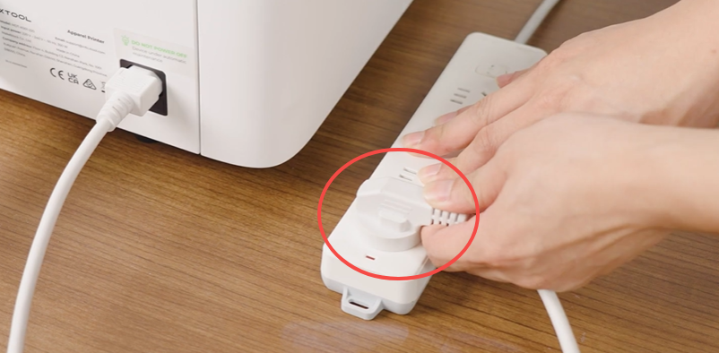
- Power cycle the printer:
- Unplug the power cord from the wall outlet (not from the machine).
- Wait for at least 1 minute before reconnecting.
- Plug the power cord back into the outlet and power on the machine.
- Test the connection:
- If the error persists, proceed to Step 2.
Step 2: Check for print head short circuits (Optional advanced diagnostic)
💡 If you do not have a multimeter or are unfamiliar with electrical testing, skip to Step 3.
This step checks if the White or CMYK print heads have an internal short circuit using a multimeter.
🛠️ Tools Required:
- Digital multimeter with continuity (buzzer) or resistance measurement function
Position the Print Carriage Manually:
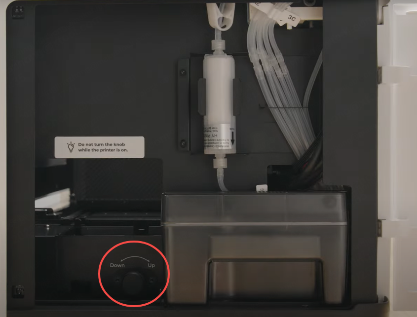
- Power Down: Turn off the printer and unplug the power cord.
- Unlock the Carriage: Open the printer's right-side panel. Rotate the ink stack knob in the "down" direction until you feel resistance. Then, rotate it in the "UP" direction for exactly 2 turns.
- Center the Carriage: Manually push the print carriage to the middle of the working area.
- Access the Board: Remove the front cover of the print carriage to expose the connections.
Measure with a Multimeter:
- Set your multimeter to Continuity (Buzzer) mode or Resistance (Ω) mode.
- Test the multimeter: Short the two probes by touching them together to ensure the multimeter is functioning properly (a beep sound indicates it is normal).
- Measurement: Place the Black probe on the GND pin and hold it steady. Use the Red probe to touch the VCOM, 42V, 5V, and 3.3V pins one by one. (Refer to the pinout diagram below)
Analyze Results:
- Continuity Mode: Check if touching any pin causes the buzzer to sound. If it beeps, it indicates a short circuit, meaning the print head is damaged.
- Resistance Mode: Check if the resistance reading on any pin is far below the normal value. If the reading is only a few kΩ or lower, it indicates a short circuit, meaning the print head is damaged.
Action:
- Document Findings: If a faulty print head is detected, please record a video or take photos of the measurement and contact xTool Customer Service.
- If you do not have a multimeter or if no issue is detected, proceed to Step 3.
Step 3: Perform a diagnostic cable swap
💡 Important: The primary purpose of this step is to gather diagnostic information for xTool technical engineers.
By swapping the print head cables, you will force the machine to generate a new error code. Comparing the "Before" and "After" codes helps engineers determine if the issue lies with the print head or the carriage controller board.
- Before You Begin: Record Initial Data
- Record Error: Note down the current error code (the number string) and take a screenshot.
- Export Log: Export the device log from xTool Studio or XCS (Instructions in the "Required Information" section below).
- Prepare the Printer
- Open the right-side panel. Rotate the ink stack knob DOWN until you feel resistance. Rotate it back UP for 1-2 turns.
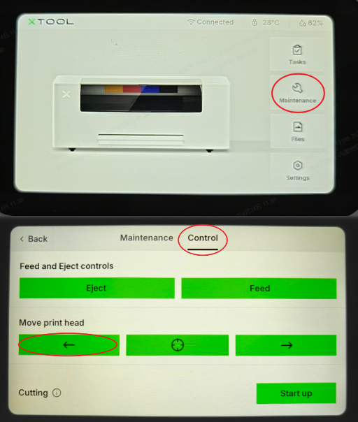
- On the printer's LCD control panel, navigate to: Maintenance > Control.
- In the "Move print head" section, tap the "Left icon" button repeatedly until the print carriage is positioned in the middle of the printer.
- Open the right-side panel. Rotate the ink stack knob DOWN until you feel resistance. Rotate it back UP for 1-2 turns.
- Swap the Cables
⚠️ CRITICAL SAFETY WARNING:
- Power off the printer completely.
- Unplug the power cord from the wall socket.
- Do not proceed until power is completely disconnected.
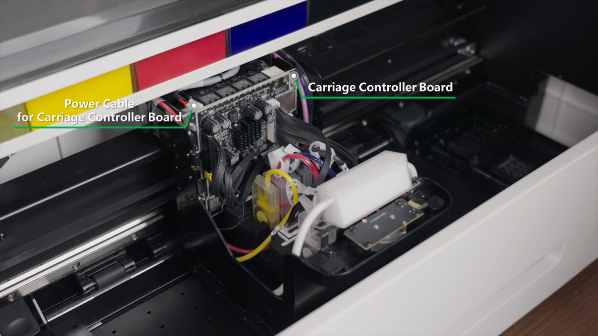
- Carefully swap the positions of the two print head connection cables on the carriage controller board.
- After Swapping: Record New Data
- Plug in and power on the printer.
- Observe: A new error message/code will likely appear. Record this new code and take a photo.
- Power Cycle Sequence: Perform 2-3 power cycles.
- Instruction: Unplug power > Wait 15 seconds > Plug in > Power on. Repeat.
- Export Log: Export the device log again (label it "After Swap").
- Restore Original Connections
- CRITICAL: Once you have collected the "after" data, power off the printer and unplug it again.
- Swap the two print head connection cables back to their original positions.
- After restoring the original connections, proceed to Step 4.
Step 4: Check the power supply to the carriage controller board
⚠️ DANGER: Electrical Safety Warning
Exercise extreme caution when working with electrical components.
This step involves checking electrical components. If you are not qualified to use a multimeter, please skip to Step 5.
- Visually Inspect the Power Cable:
- With the printer powered off and unplugged, detach the print carriage top cover and visually inspect the power supply cable connected to the carriage controller board to ensure it is securely connected.
- Test Voltage (Optional for Advanced Users Only):
- If you have a multimeter and are qualified to use it, you can test the output voltage of the power supply line at the carriage controller board end. The normal voltage should be 42V DC.
- If the voltage is abnormal or absent, there may be an issue with the main switched-mode power supply or its connection. This requires disassembling the printer casing to inspect.
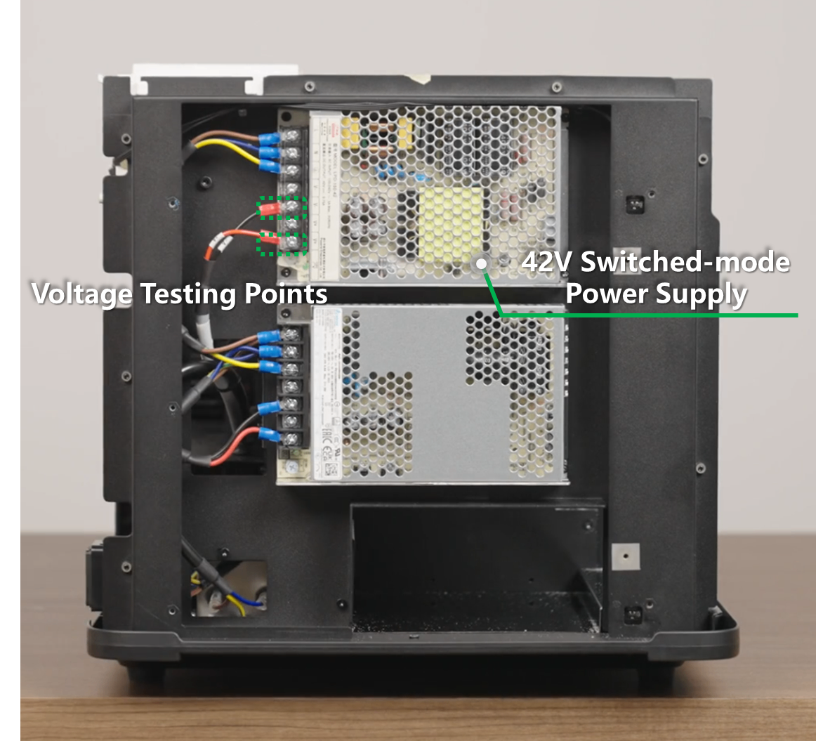
- Test Switched-Mode Power Supply:
- Check if the power supply cables are properly connected.
- Use a multimeter (DC 100V setting) to measure output voltage with the printer powered on.
- Expected output: 42V DC.
- Video Guide for reference: Replace the Switched-Mode Power Supply for xTool Apparel Printer
- ⚠️ Electrical Safety Warning: DO NOT touch any AC power lines. Perform measurements under technical supervision ONLY.
- If the power supply appears normal, proceed to the next step.
Step 5: Replace component(s)
The final step is to have the diagnostic data you collected analyzed by the xTool technical engineers.
- Please contact xTool Customer Service by submitting a ticket via the "Submit a Ticket" button in the "Help Ticket" section below.
- Provide them with all the information you have gathered:
- The original error code screenshot and log file.
- The new error code screenshot and log file (from after the cable swap).
- Any photos or videos you took during the process.
- Based on their analysis of the change in error codes, they will determine if the print head or the carriage controller board is malfunctioning and guide you on the next steps, which may include replacing the appropriate part.
- Relevant Replacement Tutorials:
If the problem persists
Should the issue persist after completing the preceding steps, please submit a ticket via the "Submit a Ticket" button in the "Help Ticket" section below. The standard response time is one business day.
Please include the following details to facilitate a quick diagnosis:
1 Work Log Files
Please export the logs twice (Before and After the cable swap in Step 3).
- Method A: Via xTool Creative Space (XCS)
Settings (gear icon) > Basic info > Export log.- Compress the folder into a .zip file.
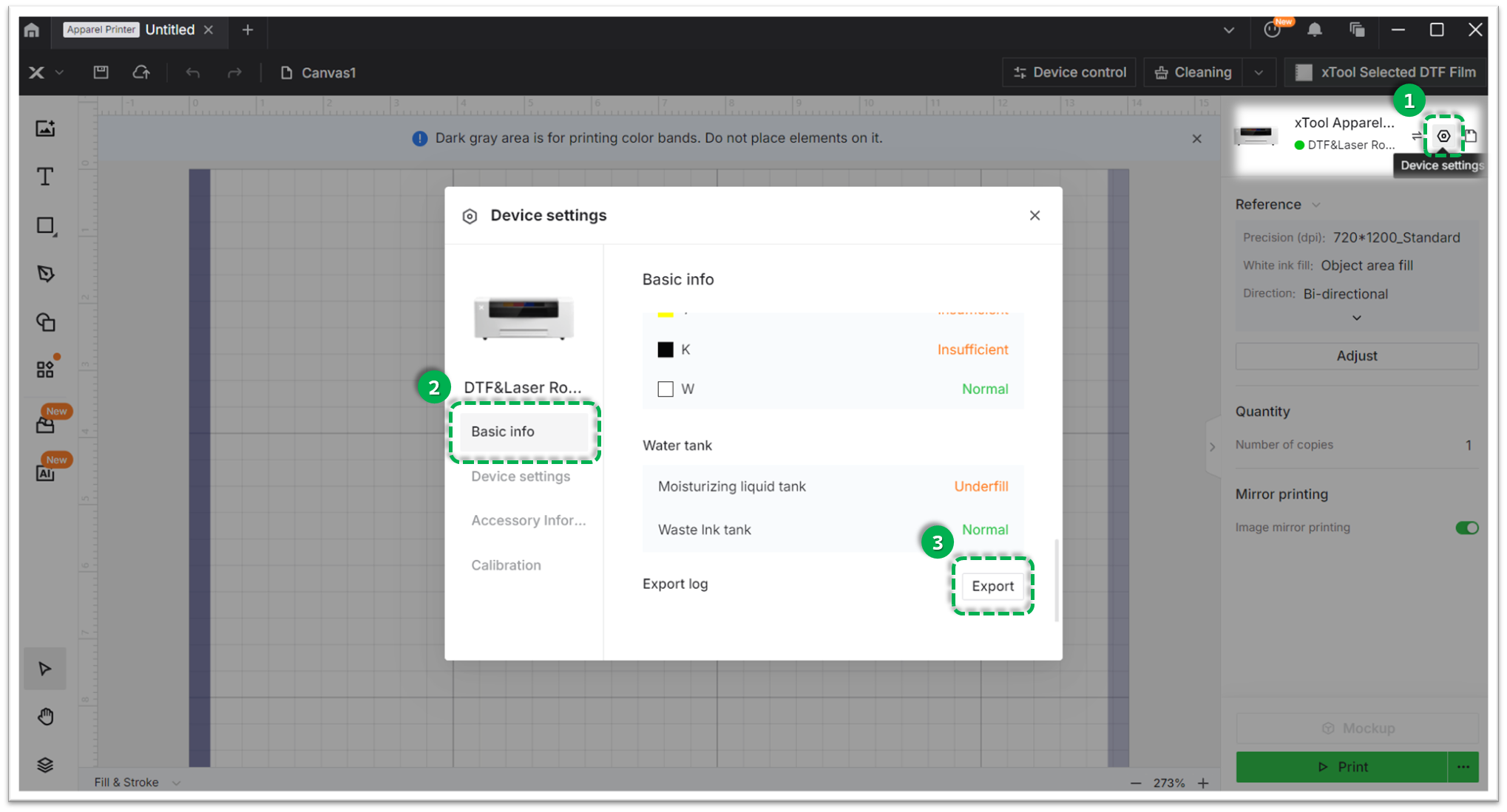
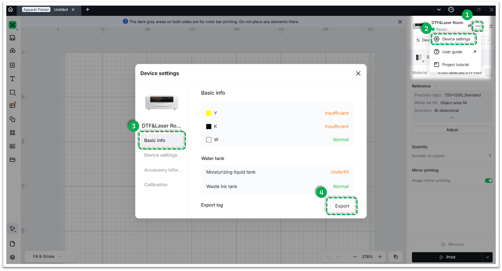
- Method B: Via xTool Studio
Three dots icon > Device Settings > Basic info > Export log.- Compress the folder into a .zip file.
2 Error Code Photos
Provide clear photos of the error messages:
- Original Error Code (Before cable swap).
- New Error Code (After cable swap).
3 Multimeter Test Results (If available)
If you performed Step 2 or Step 4, please provide the results (photos or description) of the resistance/voltage measurements.
4 Device Information
- Serial Number (SN): Located on the rear panel label.
- Firmware Version: Located in
Settings > Generalon the LCD screen.
Documentation feedback
Help improve this content by providing feedback. If this content did not meet your requirements, select "No" in the "Was this page helpful?" section below. Include specific details about what was unclear or missing in the pop-up suggestion box. Feedback submissions are reviewed by xTool technical writers to enhance future documentation.
Services & Help
Learn & Education

Copyright © 2025 xTool All Rights Reserved.