xTool F2 Ultra Conveyor Calibrations and Belt Replacement
Updated Jul 10,2025
Updated Jul 10,2025
Calibrate the conveyor
There are three types of calibration for the conveyor: belt installation calibration, angle calibration, and x-axis calibration.
Belt installation calibration is to mechanically calibrate the position and tension of the belt so as to ensure proper movement of the belt. If the belt is moving properly, you do not need to perform this calibration. After calibrating the belt, you must perform angle and x-axis calibrations in sequence to ensure motion accuracy.
If the belt of the conveyor moves properly, but the moving direction and distance are not accurate, you need to perform angle and x-axis calibration in sequence.
Calibration type
Scenario
Belt installation calibration
The belt not moving properly (For example, the belt gets stuck, lags, produces noises, or deviates from the expected direction)
Angle calibration
Moved for a large distance
Conveyed a heavy material (> 1 kg)
Belt replaced
X-axis calibration
Moved for a large distance
Conveyed a heavy material (> 1 kg)
Belt replaced
Belt installation calibration
If the belt does not move properly, for example, it gets stuck, lags, produces noise, or deviates from the expected direction, it may be that the belt is not properly installed. You need to adjust and calibrate the belt for better installation.
Tools needed:
2.5 mm screwdriver (delivered with the belt)
Pry bar (optional)
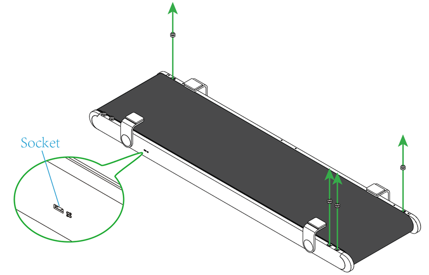
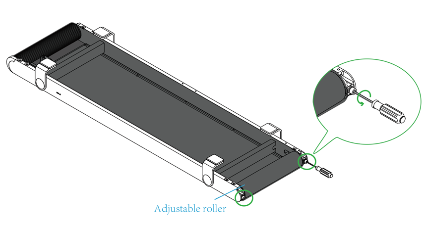
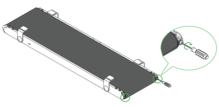
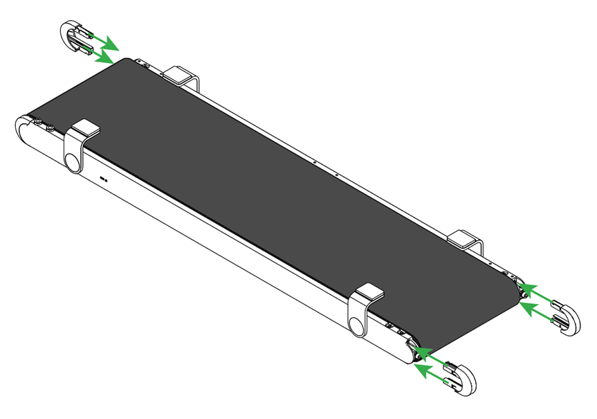
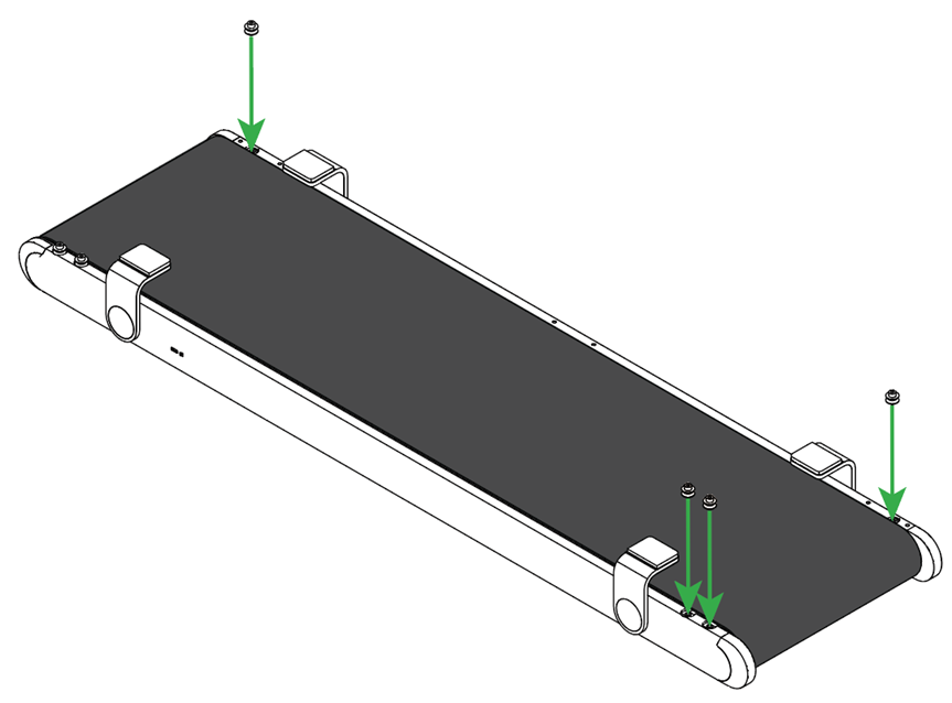
(1) Turn the conveyor over. Use the screwdriver supplied with the conveyor belt to remove the screws and V groove bearings in the three corners except for the corner where the socket is located.
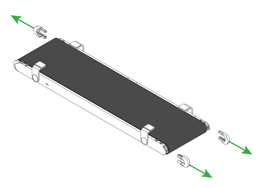
(2) Remove the covers from the three corners.
Note: If the cover is difficult to remove, use a tool such as a pry bar to pry it out.
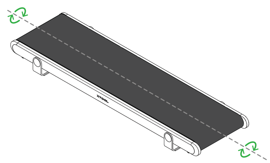
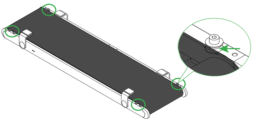
(3) Use the screwdriver to slightly loosen the two screws near the adjustable roller.
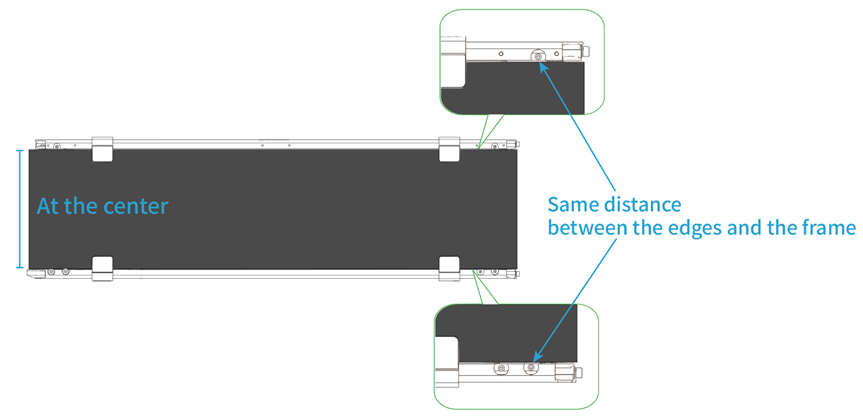
(4) Adjust the position of the belt to center it. Ensure that the two sides of the belt do not touch the bracket, and the distance between the edges and the frame are all the same.
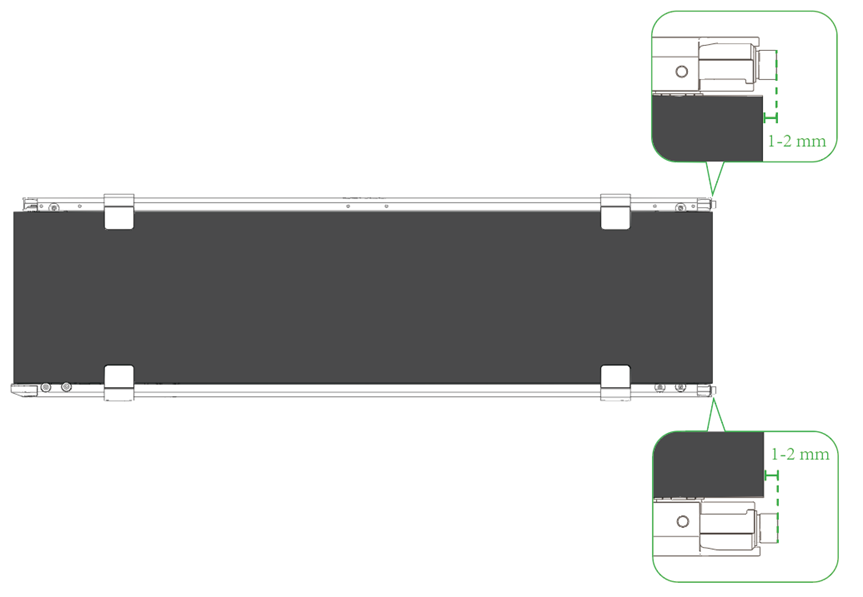
(5) Slowly tighten the two screws near the adjustable roller, keeping the belt centered and the same tension on both sides. When the belt is taut and 1-2 mm away from the screw heads, stop tightening the screws.
(6) Insert the cover back into each corner, then install the V groove bearings and screws back, and finally tuck the belt edges into all the V groove bearings.
(7) Reconnect the conveyor with xTool F2 Ultra and connect xTool F2 Ultra to XCS. In the upper right corner of the XCS, click the setting icon > Parameter settings > Conveyor test before calibration > Start calibration > Conveyor test. When the conveyor is moving, check if it moves properly.
If the conveyor moves properly, the calibration is successful.
If the conveyor does not move properly, follow the same steps to calibrate the belt again.
Angle calibration
The following situations may cause an angular shift to the conveyor belt and require angle calibration:
Moved for a large distance
Conveyed a heavy material (> 1 kg)
Belt replaced
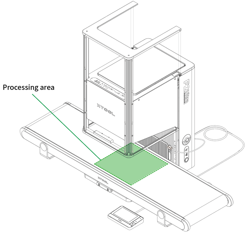
(1) Paste a piece of scratch paper (220 mm × 220 mm) in the processing area on the belt.
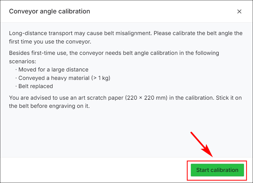
(2) Connect xTool F2 Ultra to XCS. In the upper right corner of the XCS, click the setting icon > Parameter settings > Conveyor angle calibration > Start calibration.
(3) In the displayed dialog box, click Start calibration.
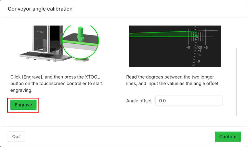
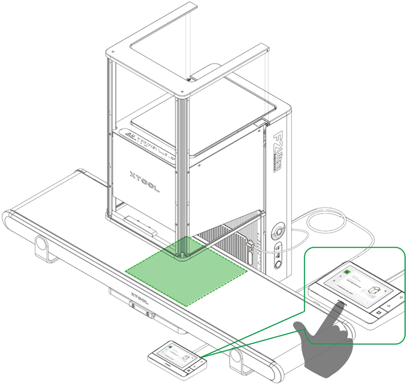
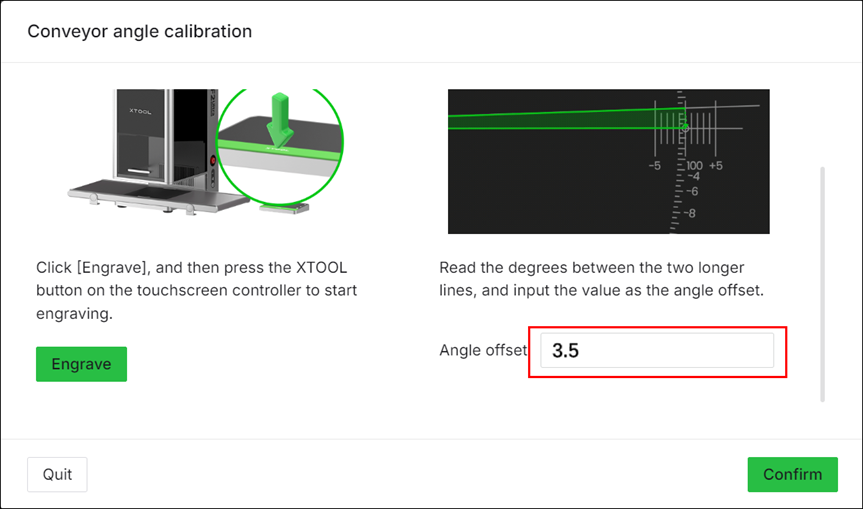
(4) Click Engrave. Put on a pair of laser safety goggles. Press the XTOOL Start/Stop button on the touchscreen controller to start engraving on the scratch paper.
Note: When xTool F2 Ultra is used with a conveyor, its protective enclosure cannot be fully closed. For your safety, it is recommended that you wear laser safety goggles that can shield laser beams of 445 nm ± 15 nm and 1064 nm ± 5 nmwavelengths during processing.
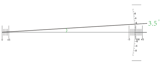
(5) After engraving, take out the scratch paper and check the engraving pattern. Read the angle between the two longer lines, and enter the value into XCS.
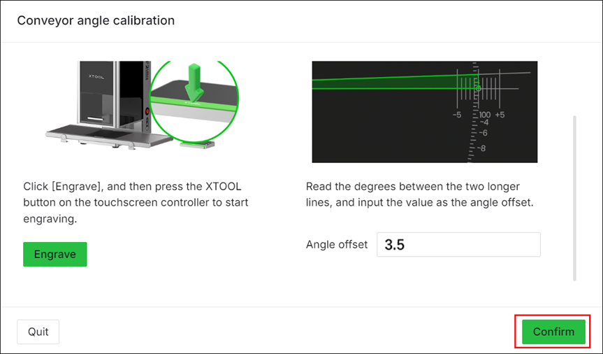
(6) Click Confirm to save the calibration result.
X-axis calibration
The following situations may cause a distance error in belt movement and require x-axis calibration:
Moved for a large distance
Conveyed a heavy material (> 1 kg)
Belt replaced
Note: Ensure that you have completed angle calibration before x-axis calibration.
(1) Paste a piece of scratch paper (220 mm × 220 mm) in the processing area on the belt.
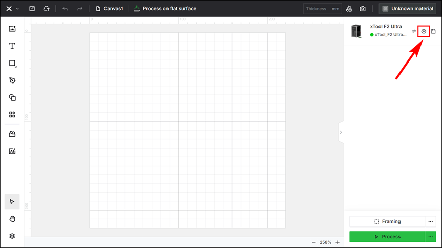
(2) Connect xTool F2 Ultra to XCS. In the upper right corner of the XCS, click the setting icon > Parameter settings > Conveyor x-axis calibration > Start calibration.
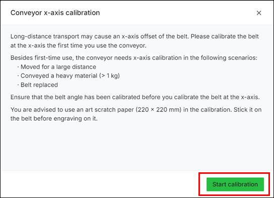
(3) In the displayed dialog box, click Start calibration.
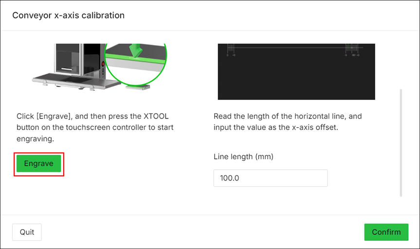
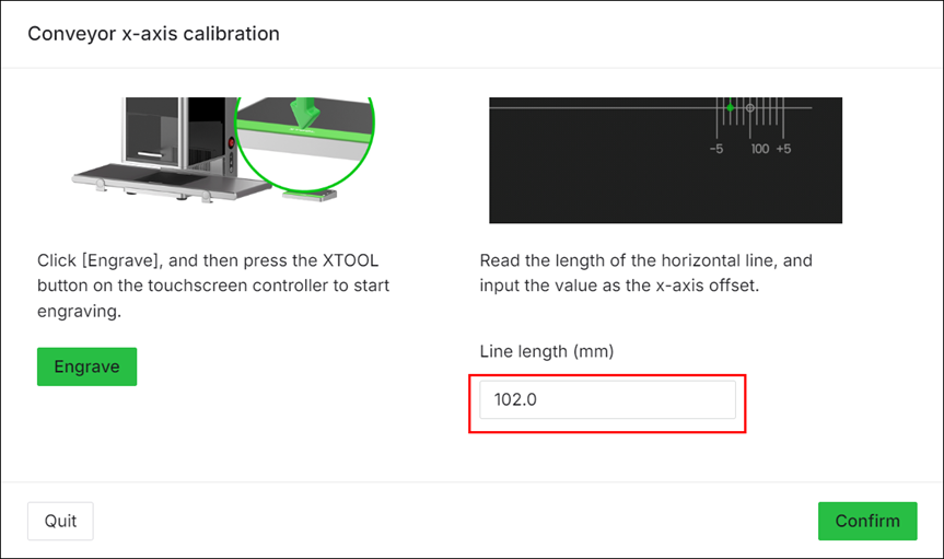
(4) Click Engrave. Put on a pair of laser safety goggles. Press the XTOOL Start/Stop button on the touchscreen controller to start engraving on the scratch paper.
Note: When xTool F2 Ultra is used with a conveyor, its protective enclosure cannot be fully closed. For your safety, it is recommended that you wear laser safety goggles that can shield laser beams of 445 nm ± 15 nm and 1064 nm ± 5 nm wavelengths during processing.
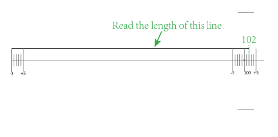
(5) After engraving, take out the scratch paper and check the engraved pattern. Read the length of the line over the scale, and enter the value into XCS.
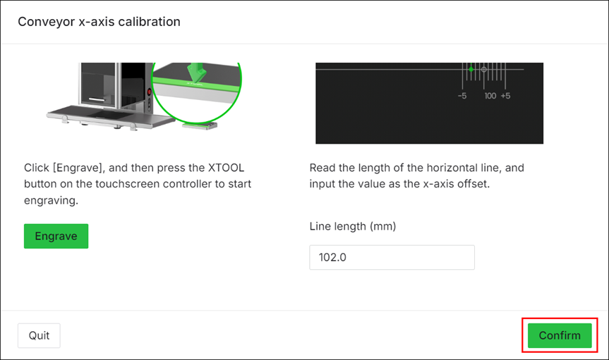
(6) Click Confirm to save the calibration result.
Replace the belt
If the belt of the conveyor is damaged, please replace the belt.
Tools needed:
2.5 mm screwdriver (delivered with the belt)
Pry bar (optional)
(1) Turn the conveyor over. Using the screwdriver supplied with the conveyor belt, remove the screws and V groove bearings in the three corners except for the corner where the socket is located.
(2) Remove the covers from the three corners except the corner where the socket is located.
Note: If the cover is difficult to remove, use a tool such as a pry bar to pry it out.
(3) Use the screwdriver to loosen the two screws near the adjustable roller. When you loosen the screws, the adjustable roller moves inward and the belt becomes slack.
Demonstration:
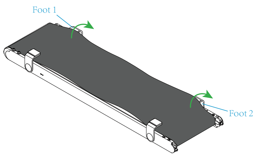
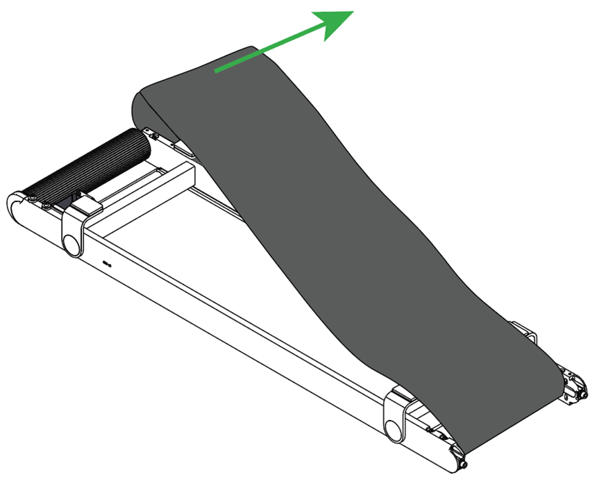
(4) When the belt is loose enough, pull out the edge of the belt from Foot 1 and Foot 2, then take off one end of the belt from the side near Foot 1, and finally remove the whole belt.
Demonstration:
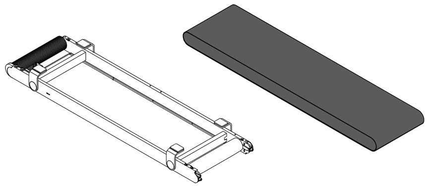
(5) Install one end of the new belt to the adjustable roller first, and then slide the other end onto the other roller.
Demonstration:
(6) Push the edges of the belt into the inner side of the conveyor feet. Slowly tighten the two screws near the adjustable roller, keeping the belt centered and the same tension on both sides. When the belt is taut and 1-2 mm away from the screw heads, stop tightening the screws.
(7) Insert the cover back into each corner, then install the V groove bearings and screws back, and finally tuck the belt edges into all the V groove bearings.
Note: After belt replacement, test the belt to see if it moves properly. If the conveyor belt moves properly, perform angle and x-axis calibrations in sequence to ensure motion accuracy.
Preview
Was this page helpful?
0 out of 0 found this helpful
Help Ticket
Use this help ticket to submit your issue. We will respond within 1 business day


 > Parameter settings > Conveyor test before calibration > Start calibration > Conveyor test. When the conveyor is moving, check if it moves properly.


 > Parameter settings > Conveyor x-axis calibration > Start calibration.