Applying Built-in Parameters
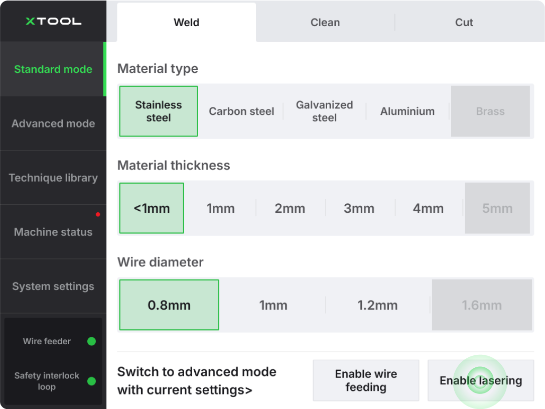
If high strength is required for the welding effect, you can choose the welding parameters in standard mode.
For example, when welding 2mm stainless steel with a wire diameter of 1.0mm, select the parameters in Lite mode as follows: Material: stainless steel, Thickness: 2mm, Wire diameter: 1.0mm.
- This method provides a completely penetrated weld, with strength higher than that of the base material.
- However, the weld may not be very bright for thicker metal. If aesthetic appearance is prioritized over strength, adjustments to the parameters are necessary.
Self-adjust Parameters
- If the requirement for sturdiness is not very high and a brighter weld is preferred, you can select parameters in standard mode that are 1mm-2mm thinner than the plate thickness.
- For example, when welding 2mm stainless steel with a wire diameter of 1.0mm, choose the process parameters as follows: Material: stainless steel, Thickness: 1mm, Wire diameter: 1.0mm.
- For more detailed parameters for different materials and processing modes, please refer to the link: https://docs.google.com/spreadsheets/d/1LQPFes92KJBtgYeAIbfB6RnNmIKU1fseTXf7GruNSKY
Impacts of Different Parameters
Different parameters have varying impacts on welding effects.
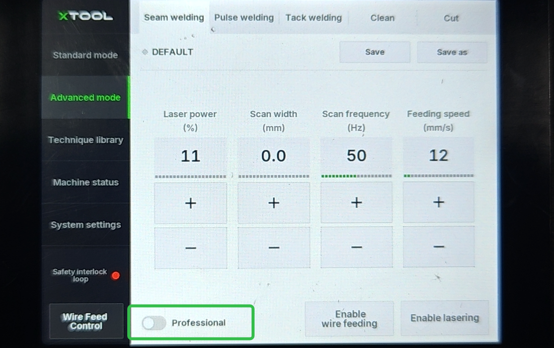
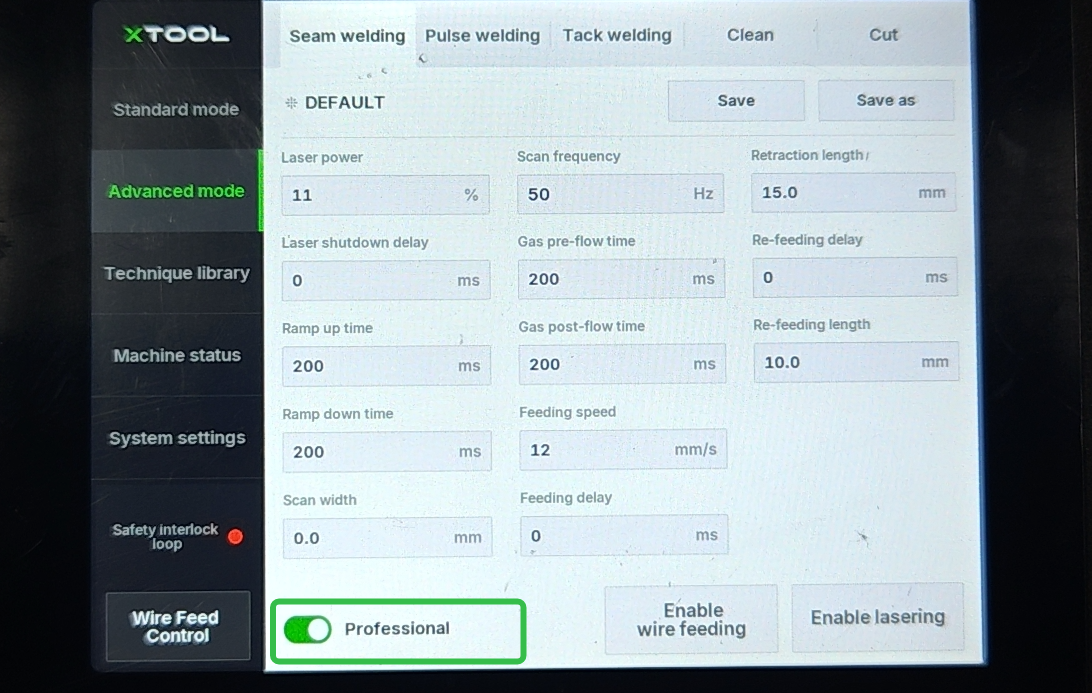
- In advanced or professional mode (Turn on professional button), you can view the values of each parameter and adjust them flexibly based on the desired outcome.
- Generally speaking, the most commonly used parameters are laser power, wire feed speed, scan frequency, scan width, and airflow rate.
|
|
Parameter | Definition | Range | Test Steps | Rule | Effects | |
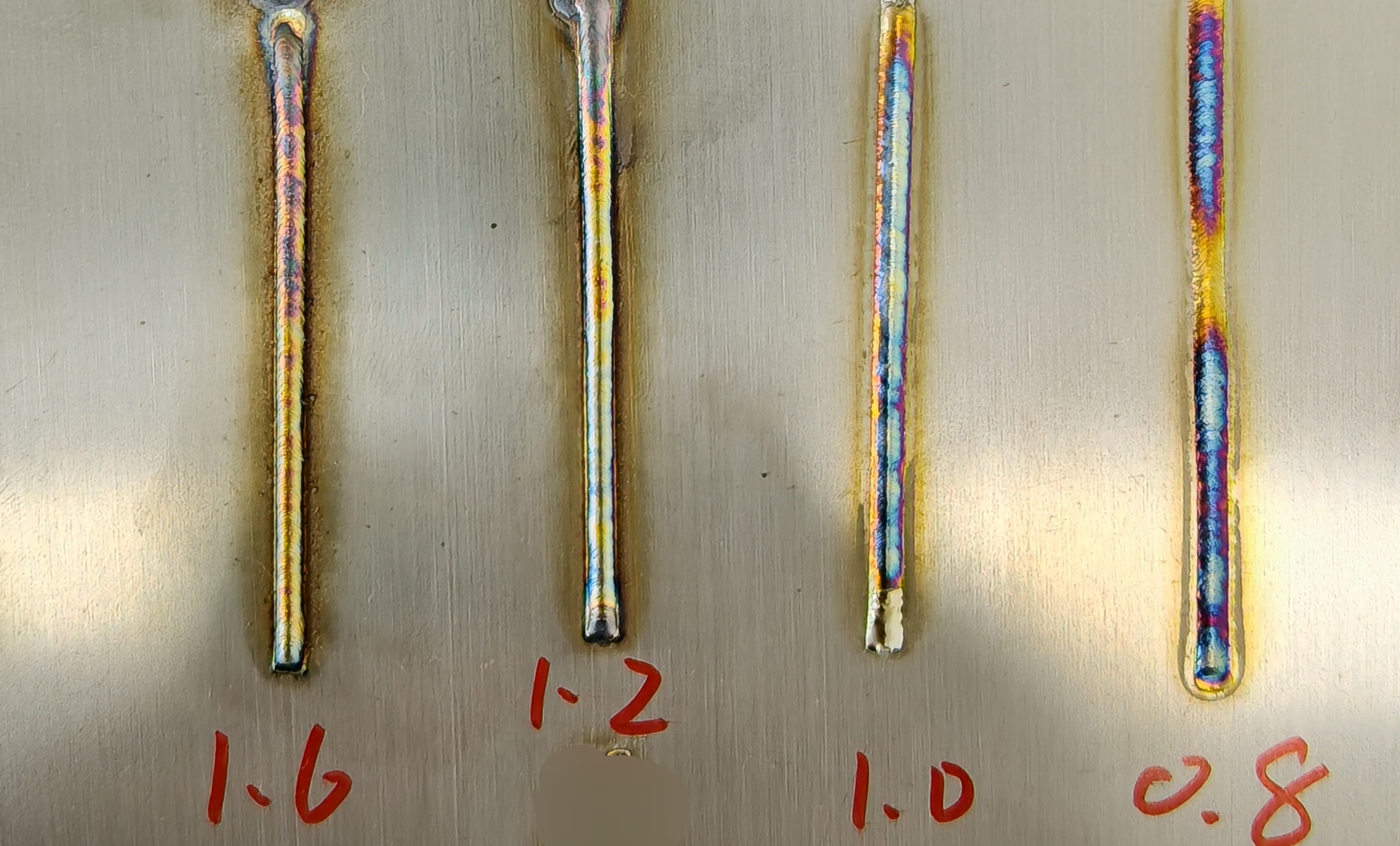
Wire Diameter (mm) | Diameter of the filler wire for laser filling welding | 0.8-1.6 mm | 0.8-1.0-1.2-1.6 | If the weld seam is constant, a larger wire diameter results in poor cladding, excessive buildup, and un-melted wire. A smaller diameter may lead to insufficient filling. |
| |
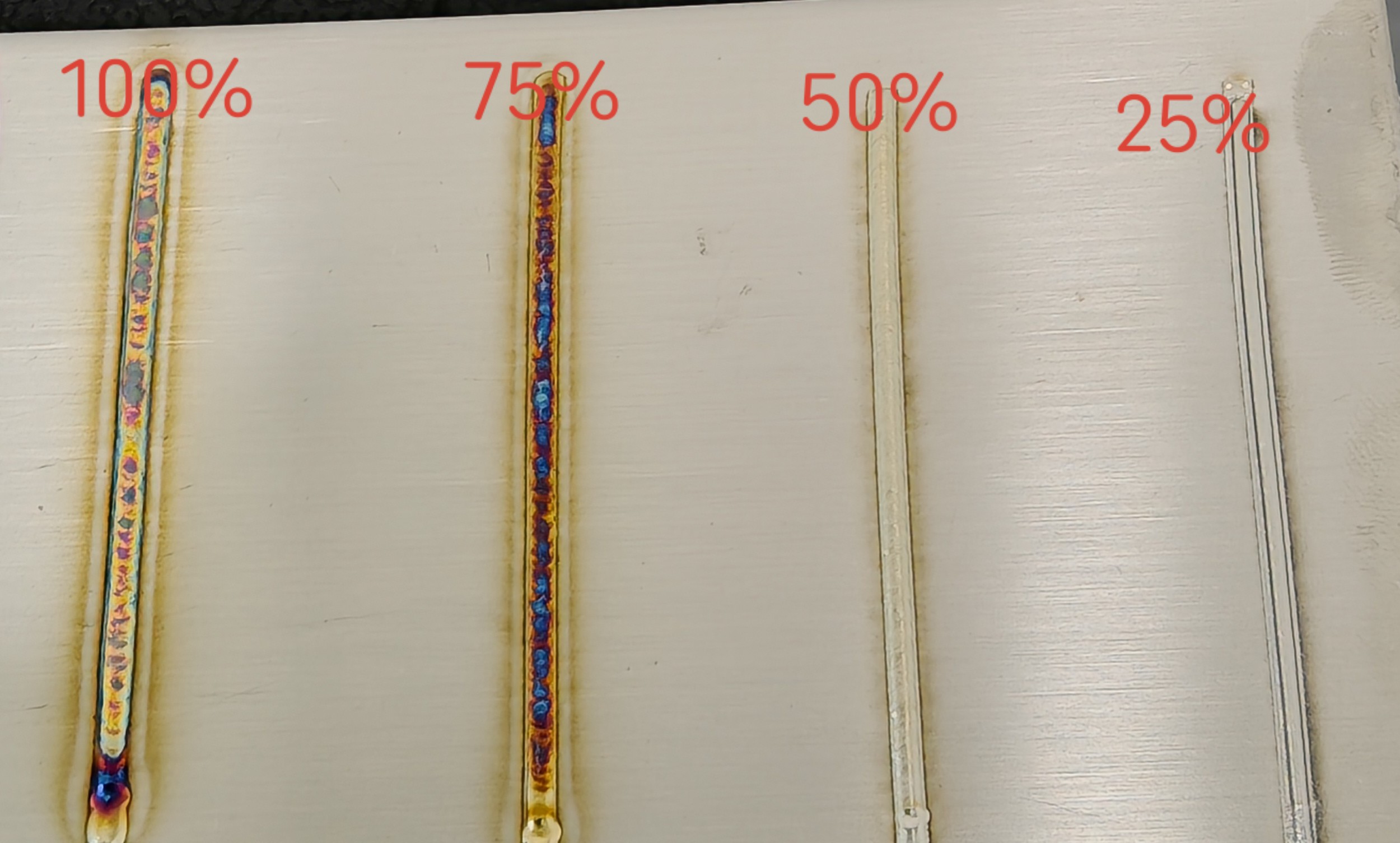
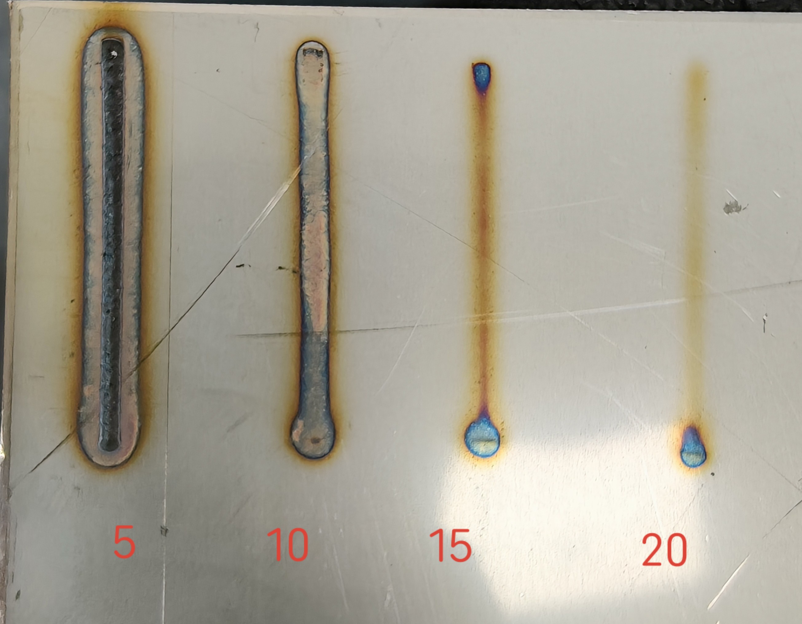
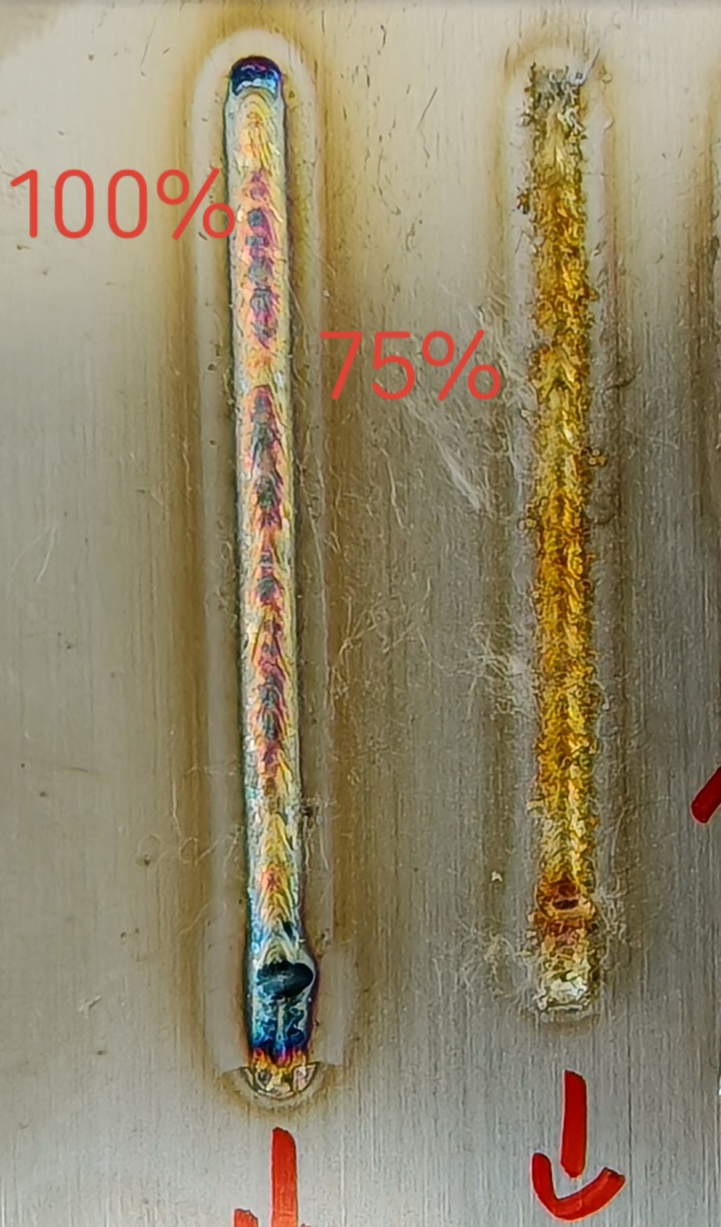
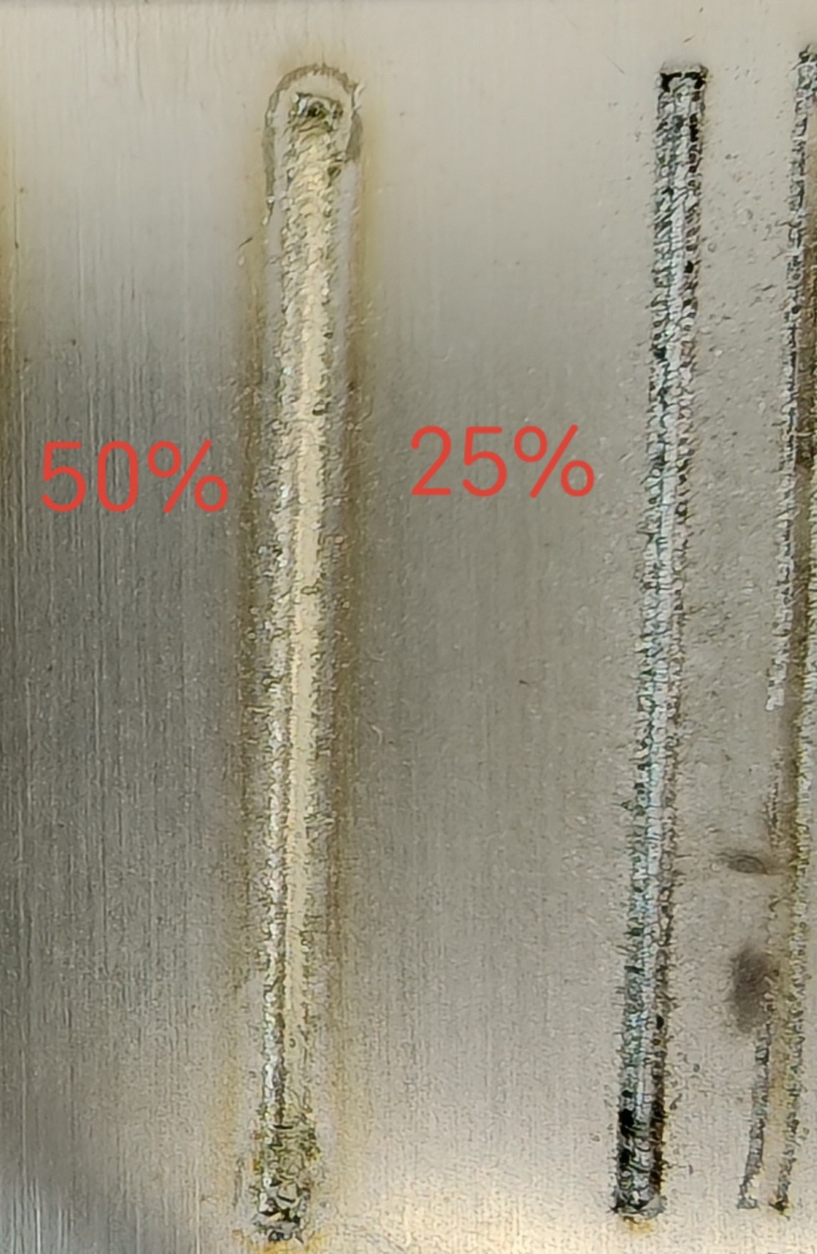
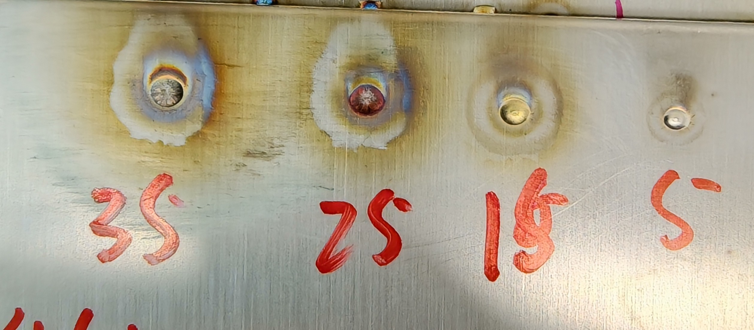
Laser Power (%) | Controls the size of laser energy during welding; adjust based on target | 10-100% | 25-50-75-100 | Higher power increases weld penetration depth, darkens the weld color, and enlarges the heat-affected zone. |
|
|
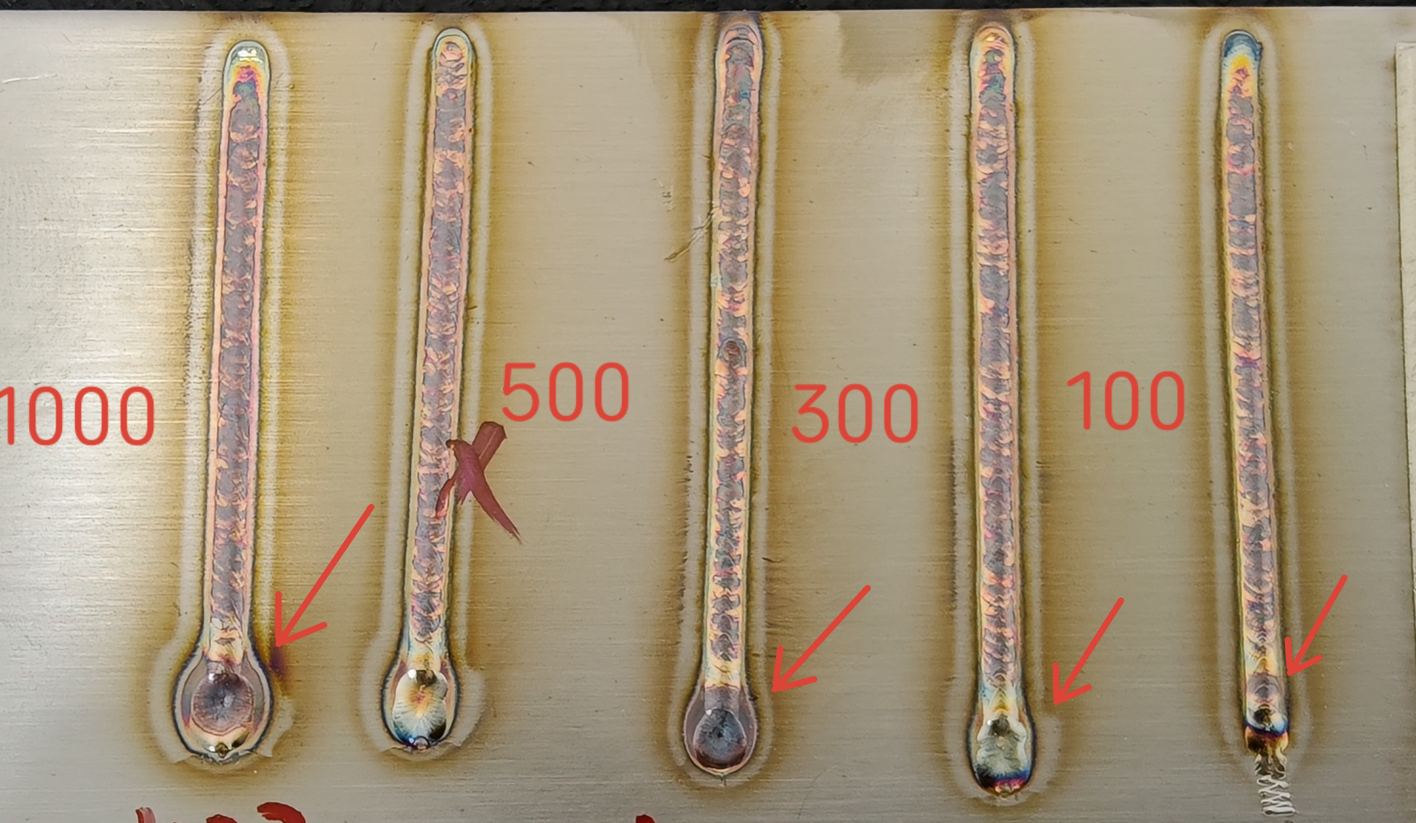
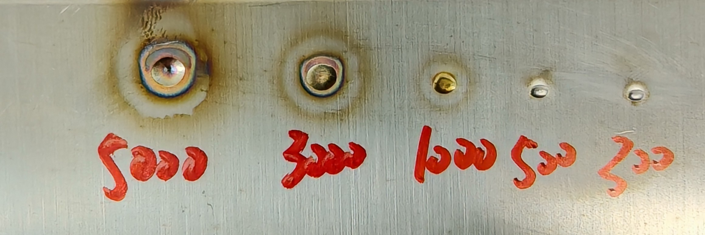
Off Light Delay (ms) | Time from the welding gun switch off to complete laser shutdown | 0-10000 ms | 100-300-500-1000 | Longer off light delay results in larger craters at the end of welding and increases wire breakage risk. |
| |
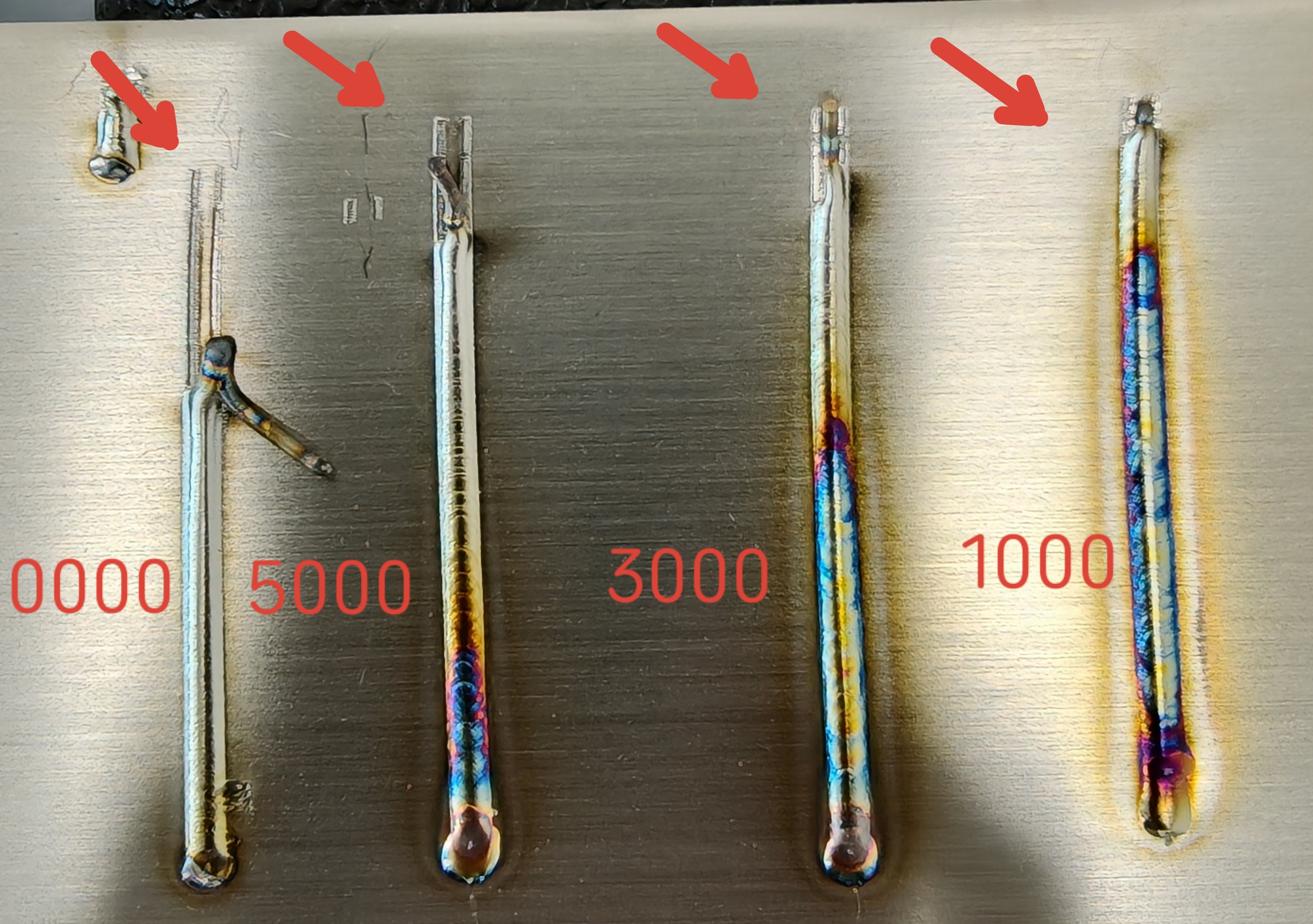
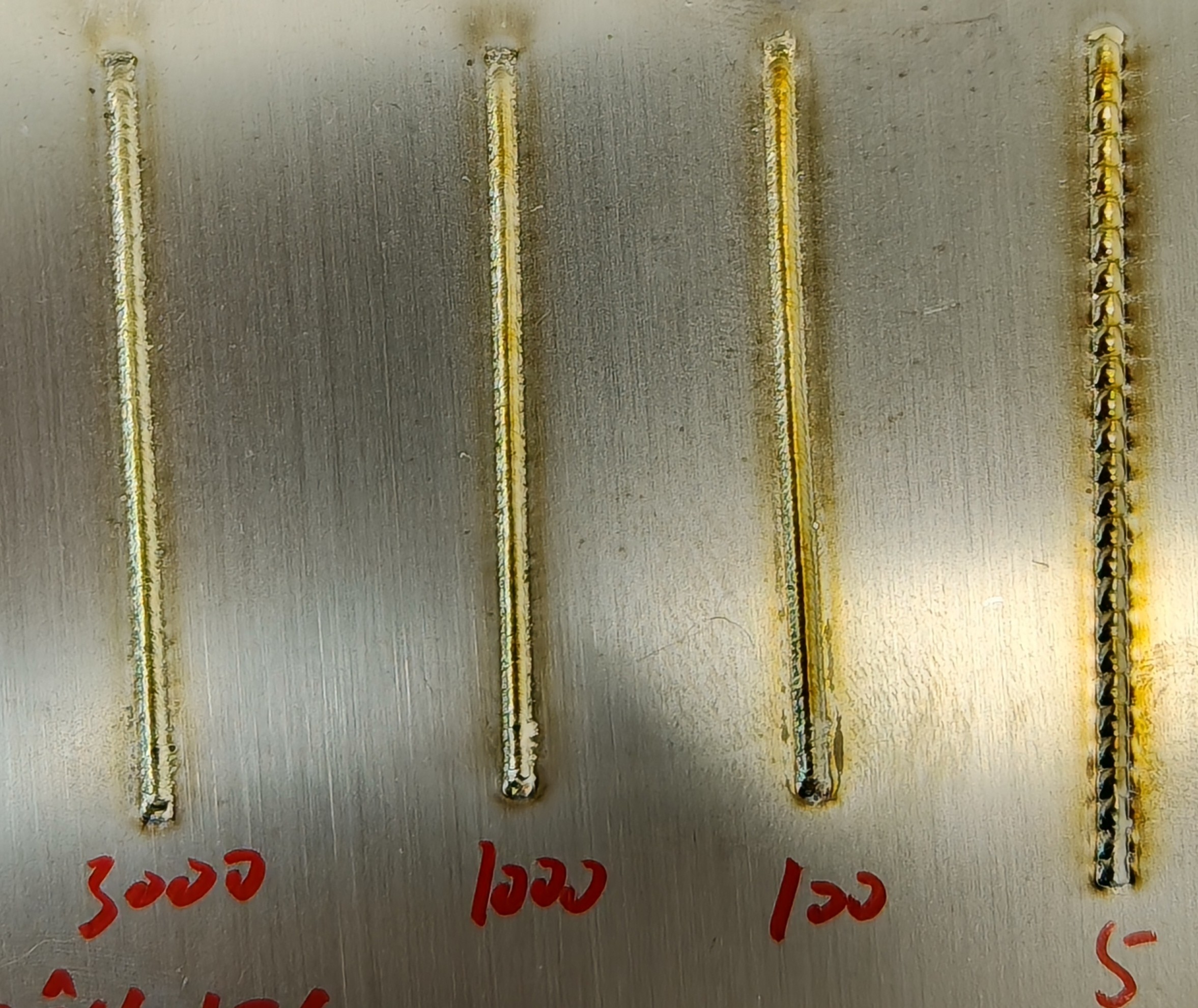
Ramp-Up Duration (ms) | Time for laser power to reach the set value after the gun is activated | 200-10000 ms | 1000-3000-5000-10000 | Longer ramp-up duration increases un-melted wire at the start of the weld. |
| |
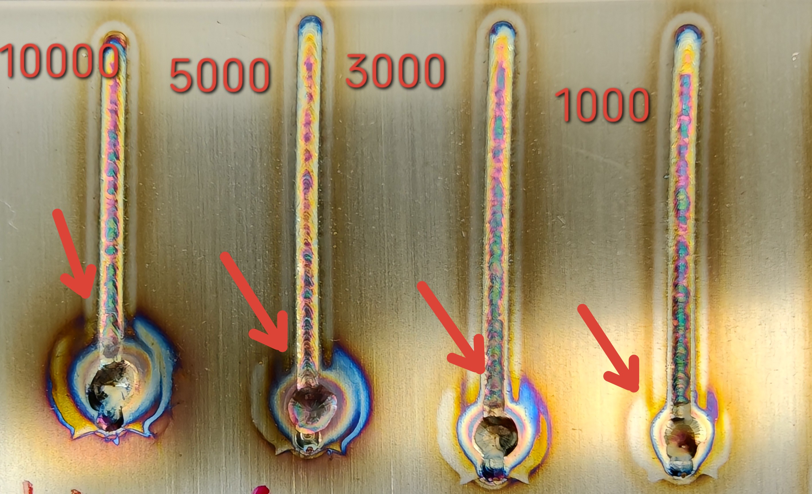
Ramp-Down Duration (ms) | Time for laser power to decrease to zero after the gun is turned off | 200-10000 ms | 1000-3000-5000-10000 | Longer ramp-down duration results in larger craters at the end of welding, leading to poor finish at the weld's end. |
| |
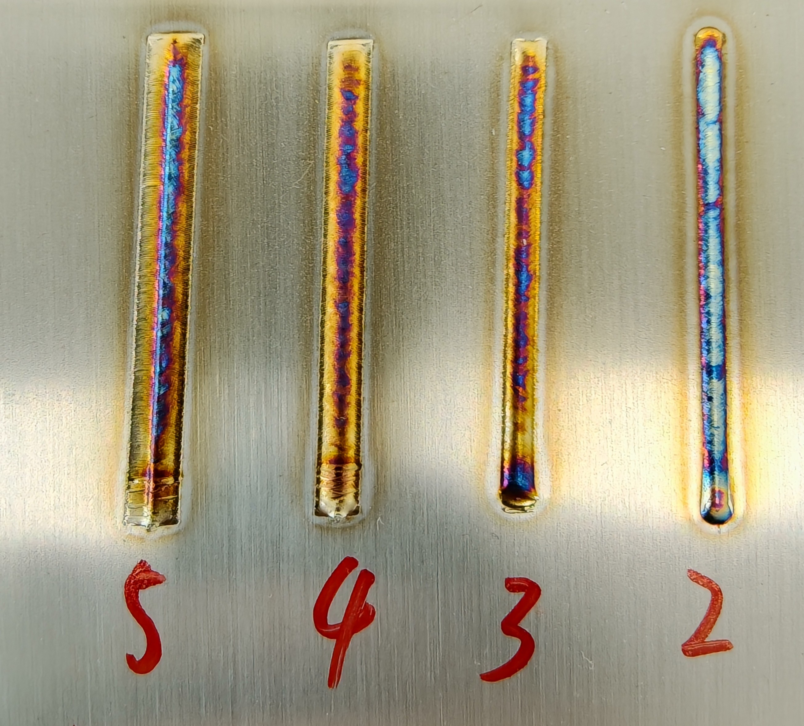
Scanning Amplitude (mm) | Range of lateral movement of the laser at the focal point | 0-5 (10) mm | 2-3-4-5 | With a fixed wire diameter, larger scanning amplitude results in inadequate melting of the wire. |
| |
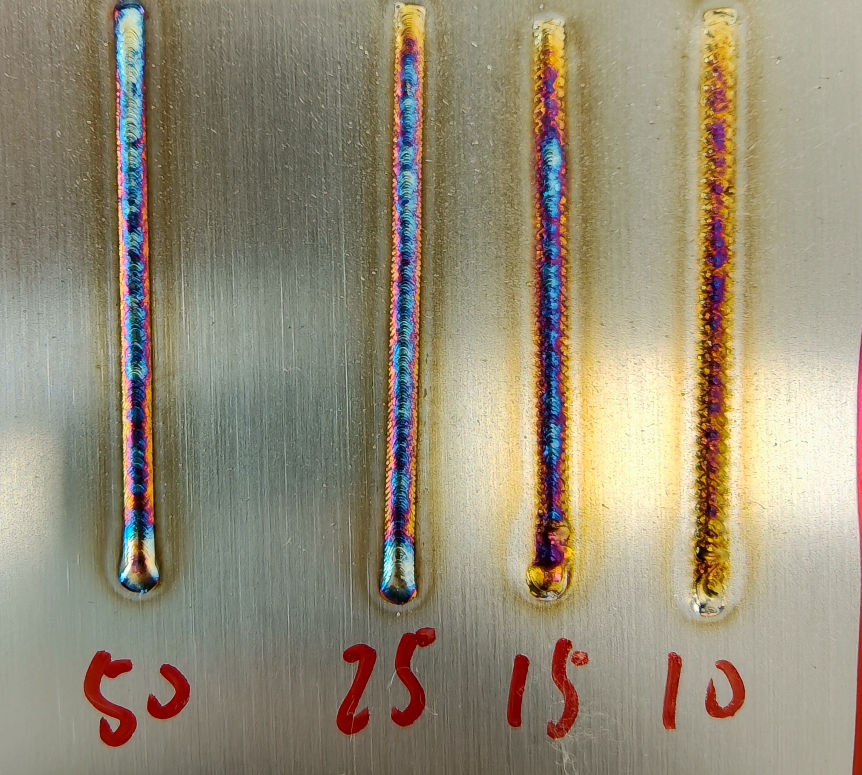
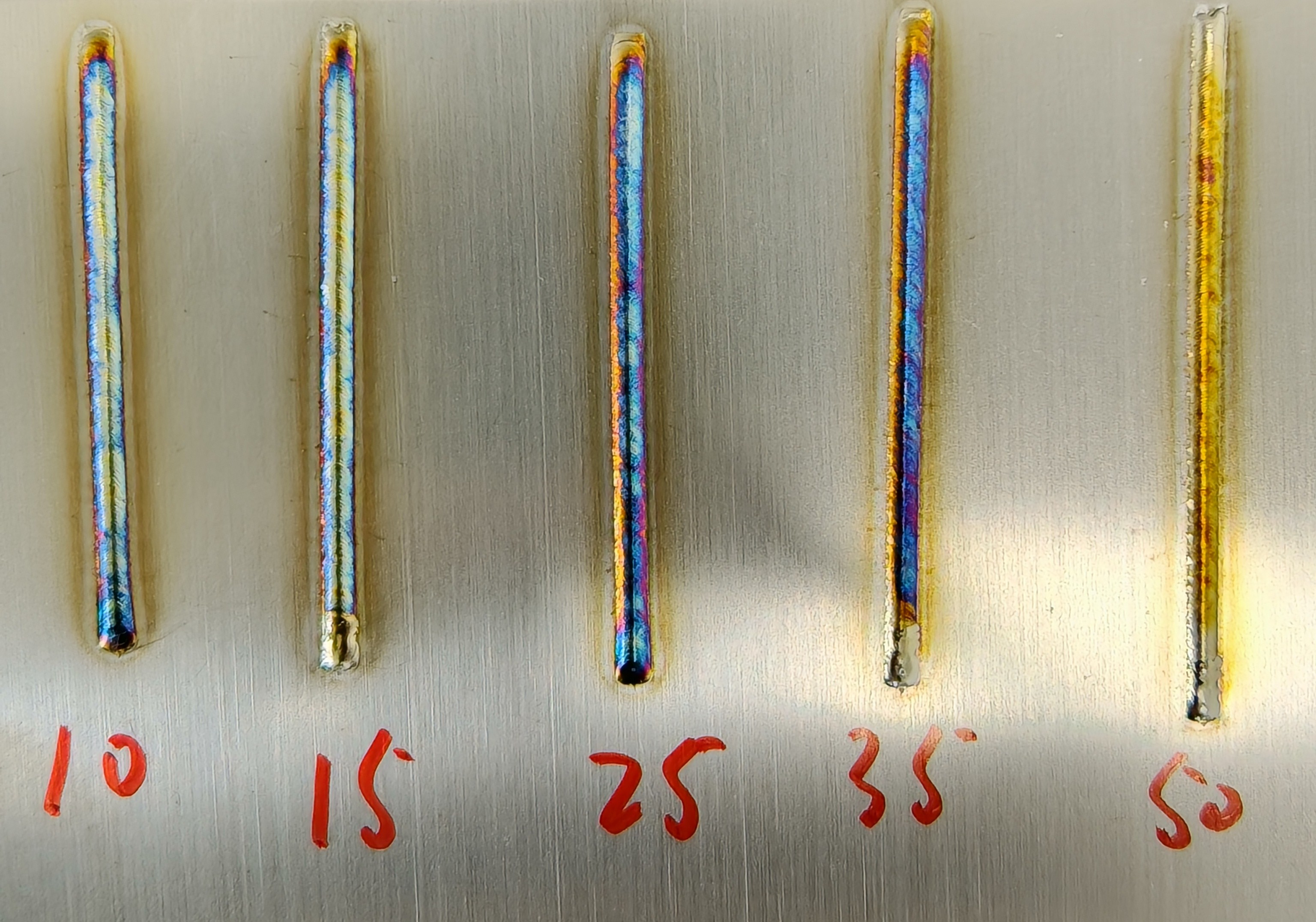
Scanning Frequency (Hz) | Number of back-and-forth movements of the laser per second | 1-100 (150) Hz | 10-15-25-50 | Smaller frequency results in jagged weld edges; larger frequency increases spatter during welding. |
| |
Gas Blow Delay (ms) | Time from activation of protective gas pressure to laser emission | 0-10000 ms | 0-1000-3000-5000 | Pre-blowing gas effectively avoids spatter at the start of welding, extending the lifespan of the protective lens, but excessive time wastes gas and increases costs. | ||
Gas Cut Delay (ms) | Time from gun switch off to reduction in protective gas pressure | 0-10000 ms | 0-1000-3000-5000 | Longer gas cut delay improves protection at the end of welding, but excessive time wastes gas and raises costs. |
| |
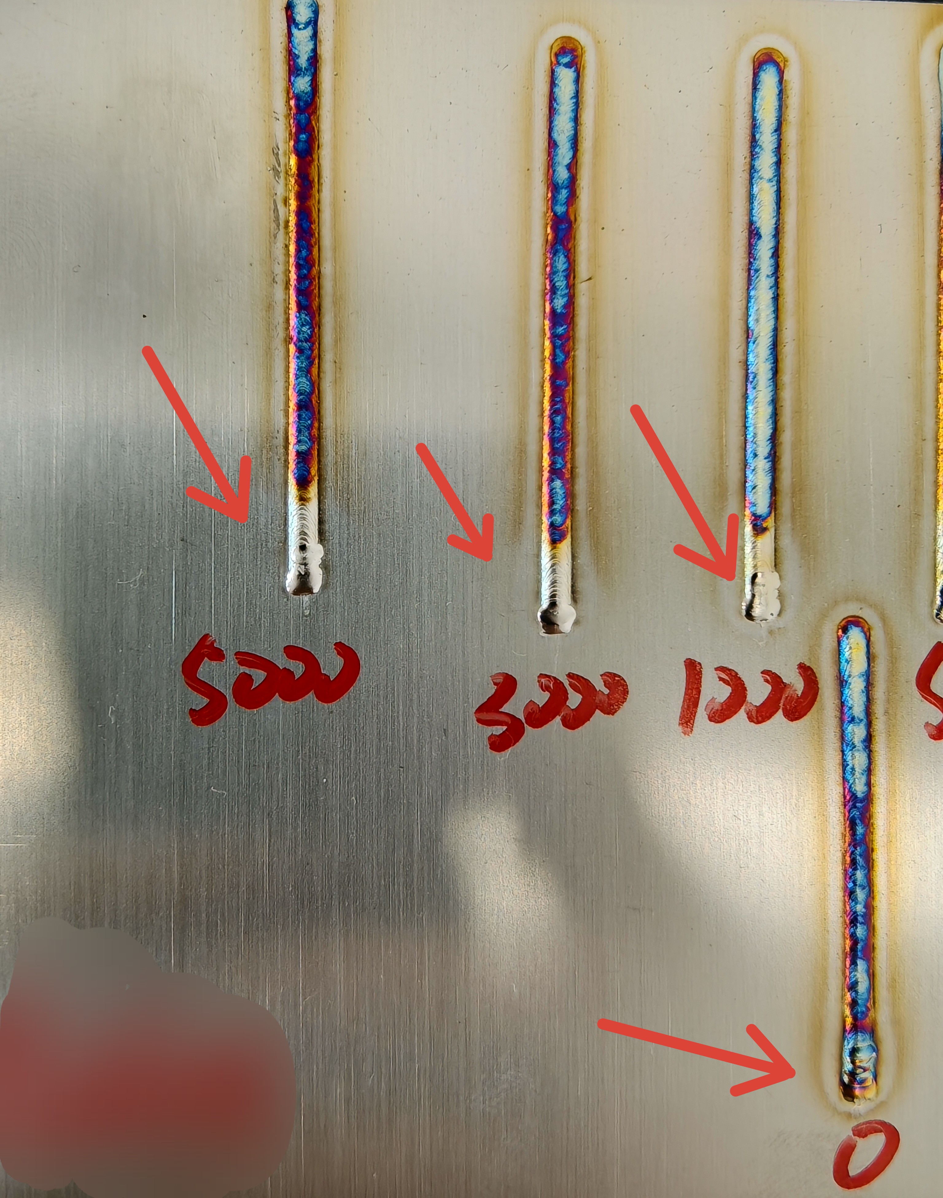
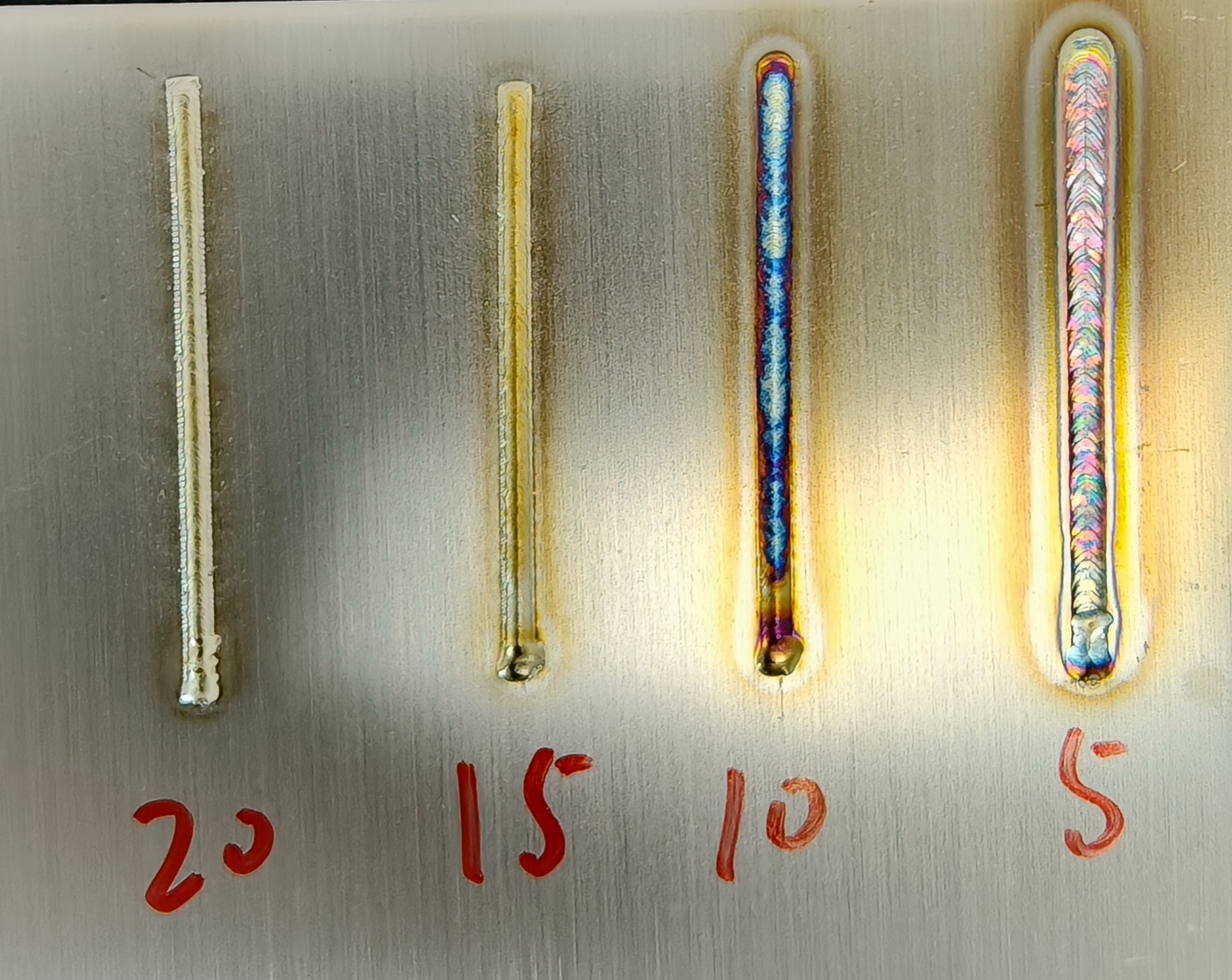
Wire Feed Speed (mm/s) | Controls the speed of wire feeding during welding | 2-100 mm/s | 5-10-15-20 | Slower feed speed increases penetration depth and heat-affected zone; faster feed speed decreases both. |
|
|
Wire Feed Delay (ms) | Delay time before wire feeding starts after triggering the gun | 0-2000 mm/s | 100-300-500-1000 | Longer delay increases the heat-affected zone at the weld start and creates larger craters. |
| |
Retract Length (mm) | Length of excess wire retracted after welding to facilitate automatic cutoff | 0-50 mm | 5-15-25-35 | Must coordinate with compensation length; excessive retraction can cause jams, while insufficient retraction fails to achieve automatic cutoff. | ||
Compensation Delay (ms) | Delay between retracted wire and compensation feed during wire break | 0-2000 ms | 100-300-500-1000 | Excessive delay affects welding efficiency and operation. | ||
Compensation Length (mm) | Length of wire fed after retraction during a break to maintain joint consistency | 0-50 mm | 5-15-25-35 | Must coordinate with retract length; excessive length may leave un-melted wire at the start of the weld, while insufficient length affects operation. | ||
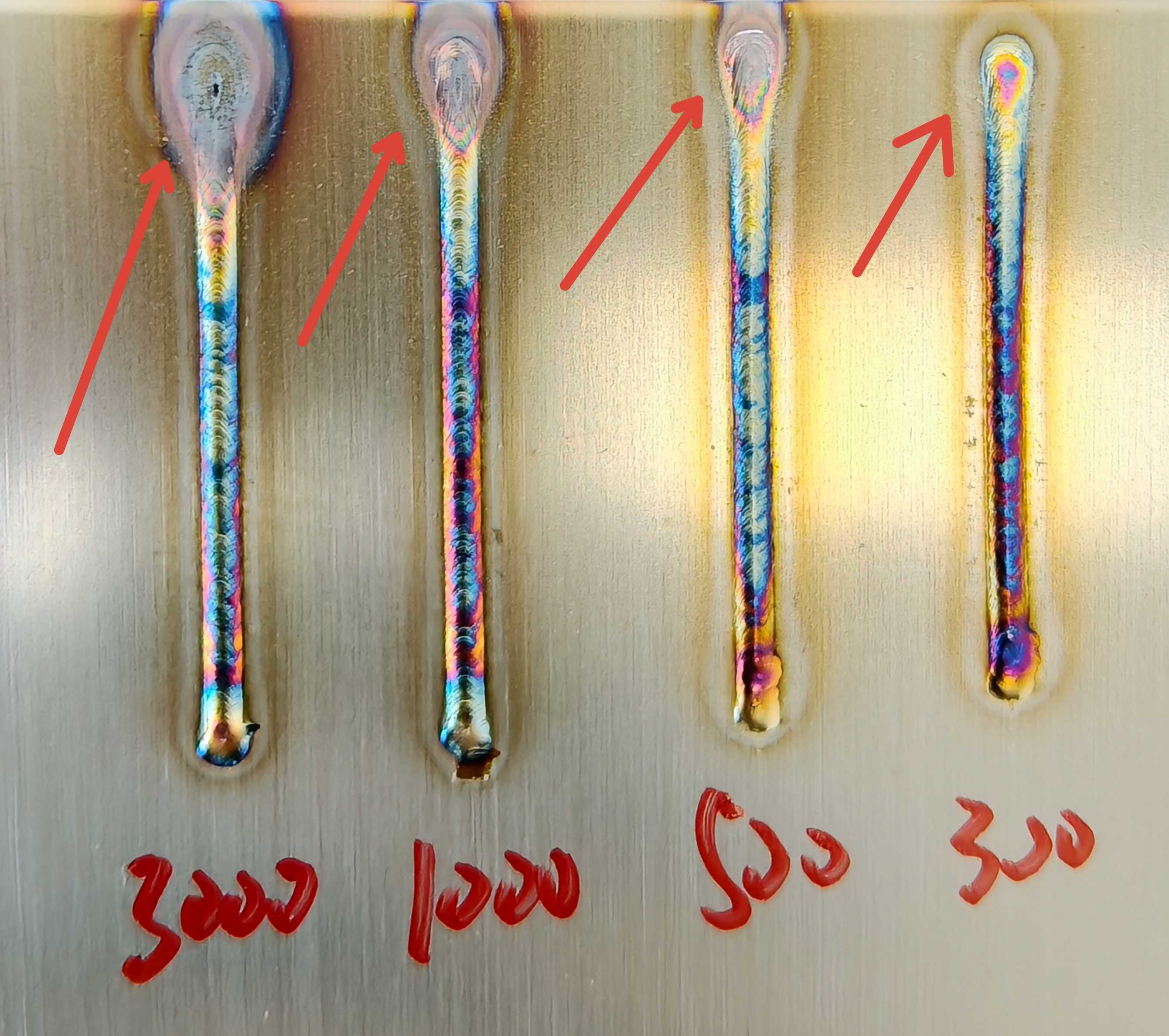
Laser Frequency (Hz) | Repetition frequency of laser waves per unit time | 0-5000 Hz | 5-100-1000-3000 | Smaller frequency results in jagged weld edges; larger frequency increases spatter during welding. |
| |
Duty Cycle (%) | Ratio of actual working time to total time within a cycle | 0-100% | 25-50-75-100 | Smaller duty cycle results in lower laser energy; larger cycle increases energy. |
|
|
Spot Duration (ms) | Duration of single spot emission | 0-10000 ms | 300-500-1000-3000-5000 | Longer duration increases energy applied to the object. |
| |
Spot Interval (ms) | Time interval between two spot emissions | 0-10000 ms | 100-300-500-1000 | Longer intervals reduce welding efficiency and operation. |
| |
Number of Spots | Number of emitted spots during a sequence | 1-1000 | 5-15-25-35 | More spots increase the energy applied to the object. |
| |
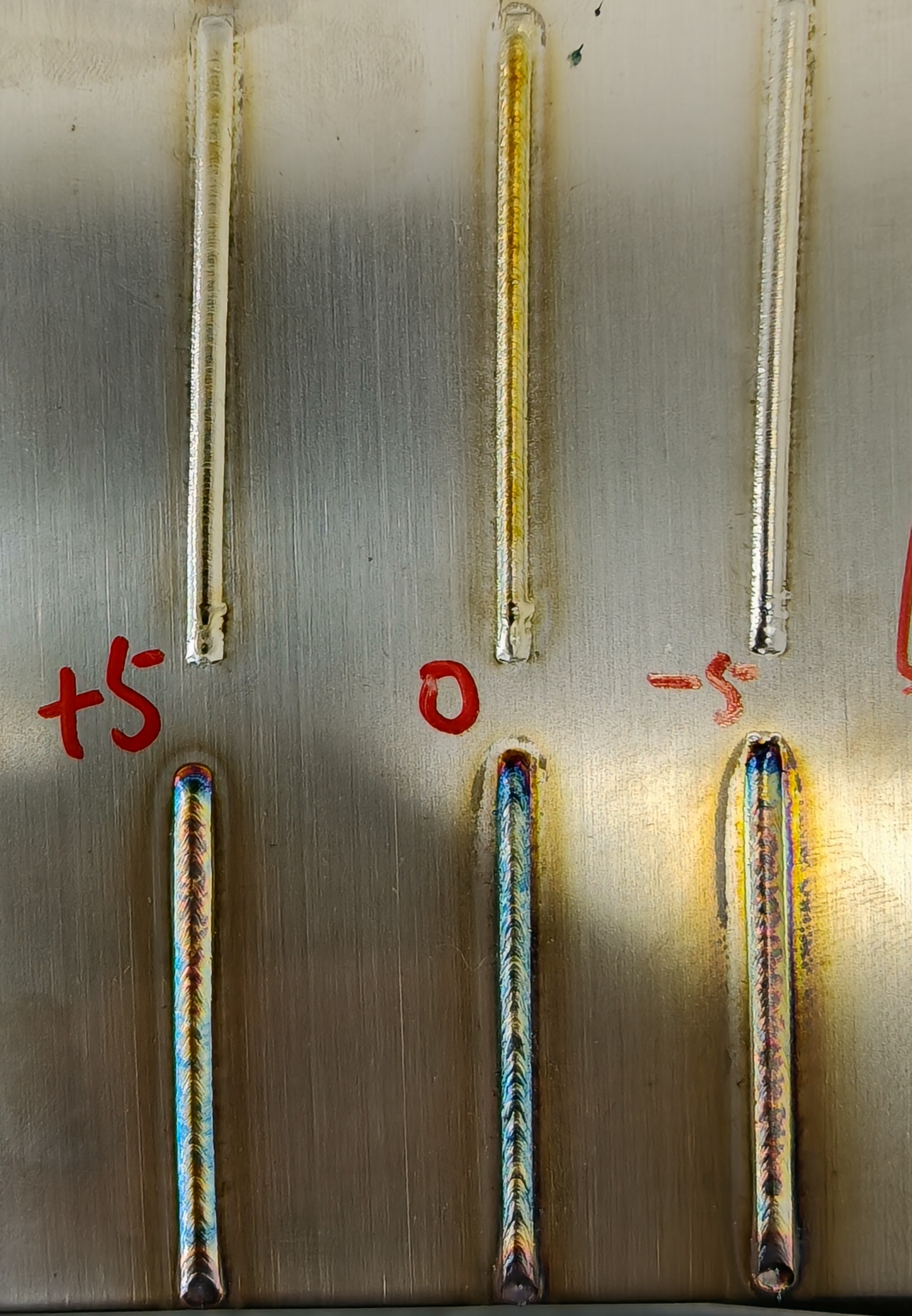
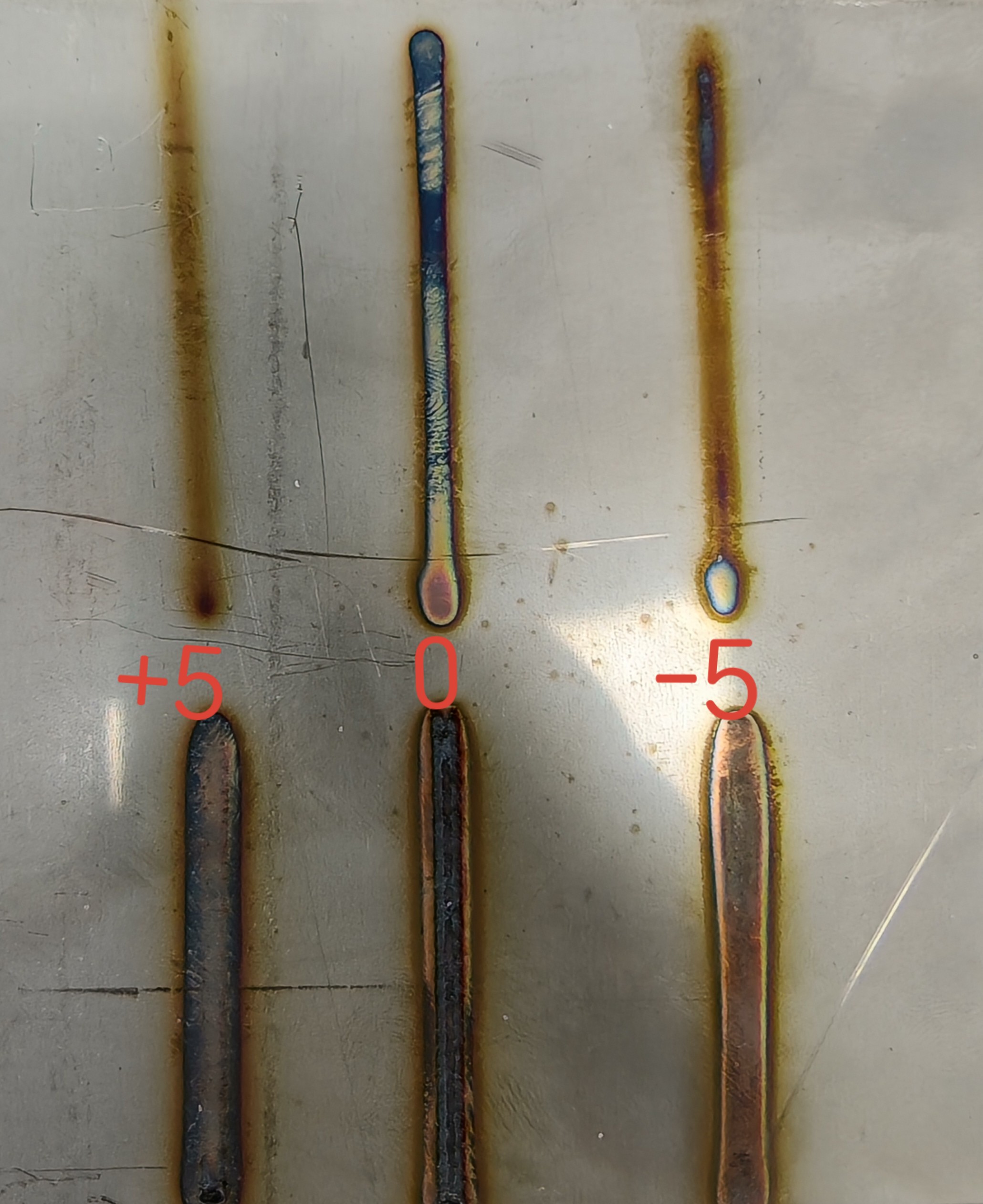
Defocus Amount (mm) | Distance from the laser focus to the surface of the workpiece | -5 to +5 mm | -5-0-+5 | Closer to the focus increases energy and penetration depth. |
|
|
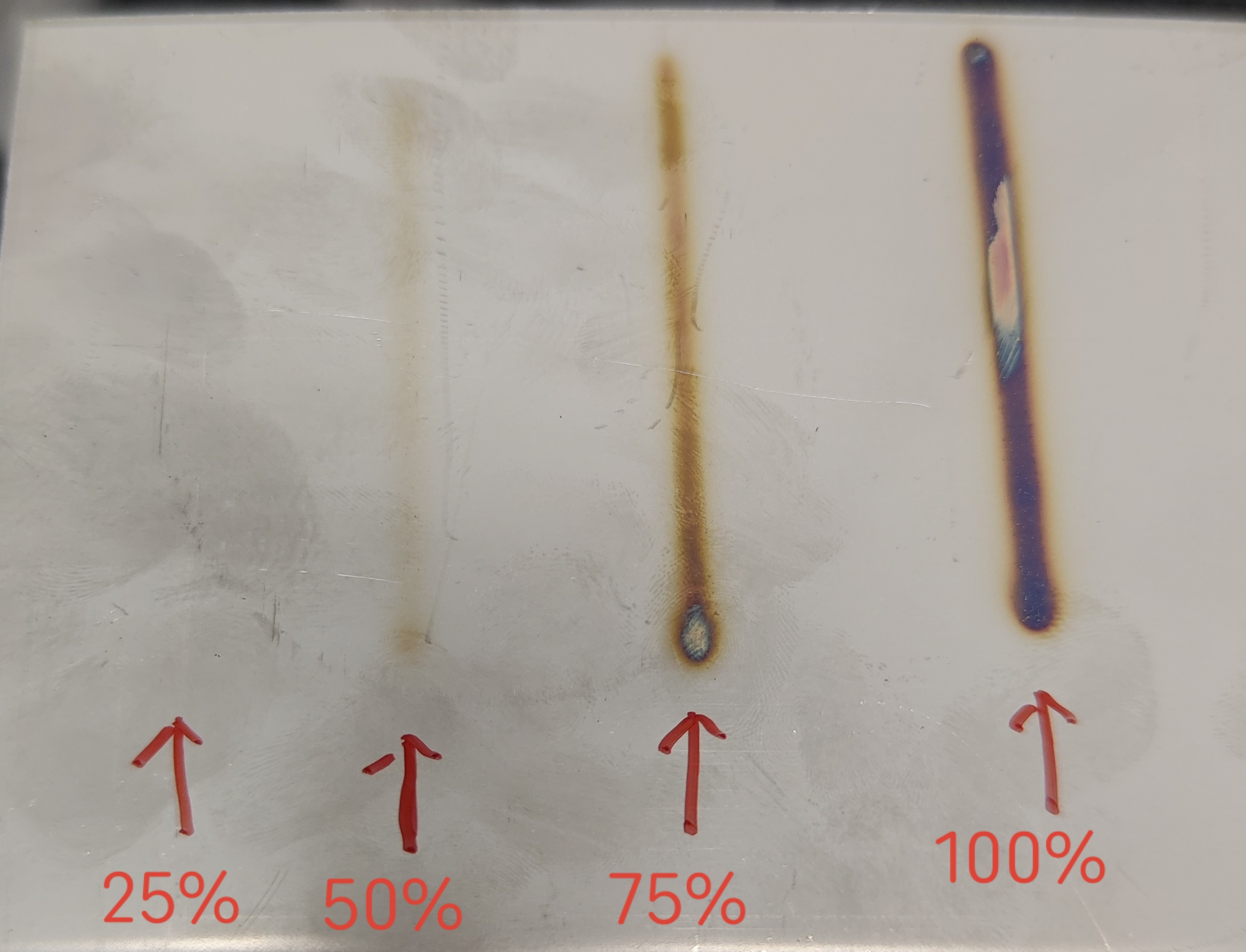
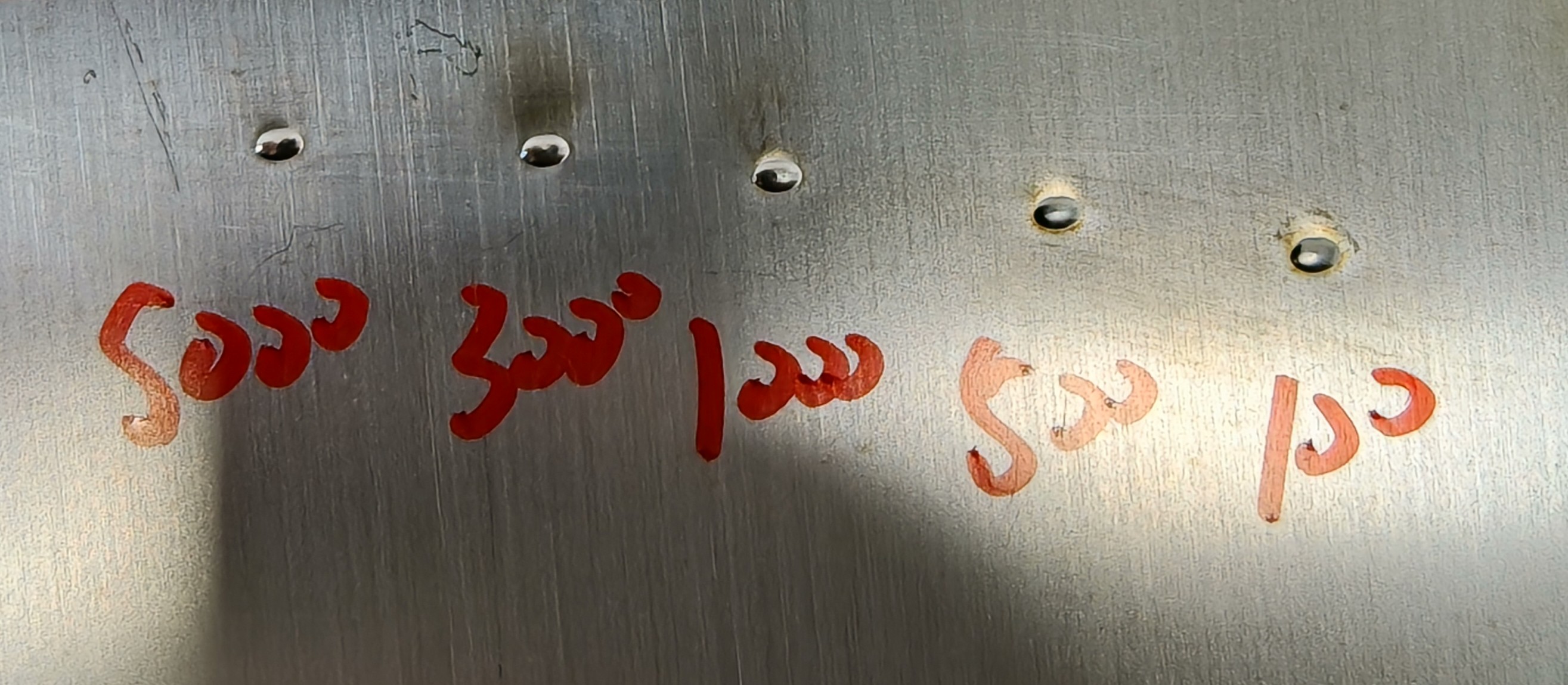
Gas Flow Rate (L/min) | Flow rate of protective gas, indicating its blowing force | 15-50 L/min | 15-25-35-50 | Smaller flow rates result in poor protection, causing blue or black weld seams. |
| |