Download PDF files (multi-language)
xTool Rotary Attachment 3 (RA3) Quick Start Guide
xTool Rotary Attachment 3 for xTool P2 and xTool P2S (Installation Guide)
xTool Rotary Attachment 3 unboxing and first use
Safety first (important)
Read and get familiar with all safety precautions and procedures before using the product. Strictly follow all safety precautions.
- Due to the size of the product, when the product is used with some xTool laser machines, it may prevent the laser machines from being properly closed. Diffused laser beams may leak out from the openings, and you may be exposed to Class 4 laser radiation. When working with the product, such laser machines should be classified as Class 4 laser machines, and ONLY professionally trained personnel are allowed to use them. When the lid is lifted during processing, strictly follow all safety precautions of the laser machine, set up a safety-controlled area under the guidance of a laser safety officer, and take adequate personal protective measures (such as wearing safety goggles) to avoid laser safety risks.
- The product features a magnetic quick-release design. Do not put your hand between magnetic parts during use to avoid pinching yourself. There is also a risk of pinching when assembling different modules, rotating the jaw chuck, and adjusting the power module and the support module.
- Keep the product away from children.
Note: Click here for multi-language safety instructions.
List of items
Unbox xTool Rotary Attachment 3 and check the items inside the pack. If you find items missing or broken, please contact us for after-sales support.
Part name | Image |
|---|---|
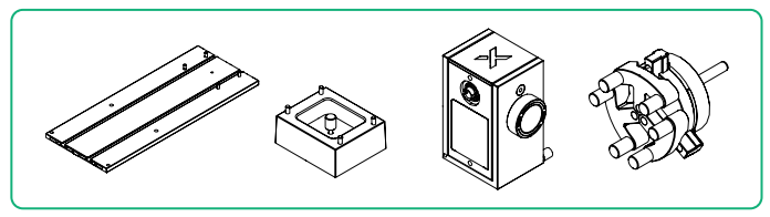
Jaw chuck |
|
Cylindrical jaw |
|
T-shaped jaw |
|
Power module |
|
Main baseplate |
|
Height-extension module |
|
Roller components |
|
Holder for roller components |
|
Roller transmission module |
|
Support module |
|
Stud components |
|
Mini level |
|
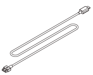
Connection cable |
|
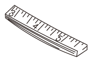
Tape measure |
|
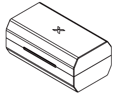
Storage box |
|
Safety Instructions |
|
Quick Start Guide |
|
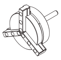
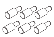
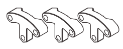
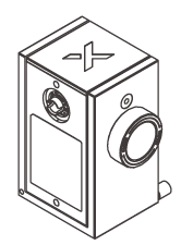
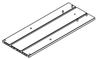
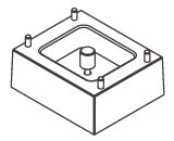
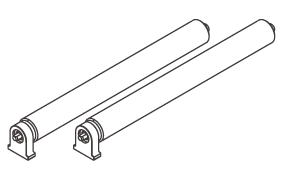
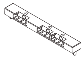
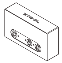
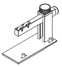
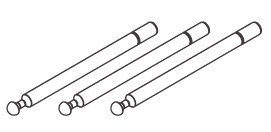
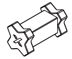
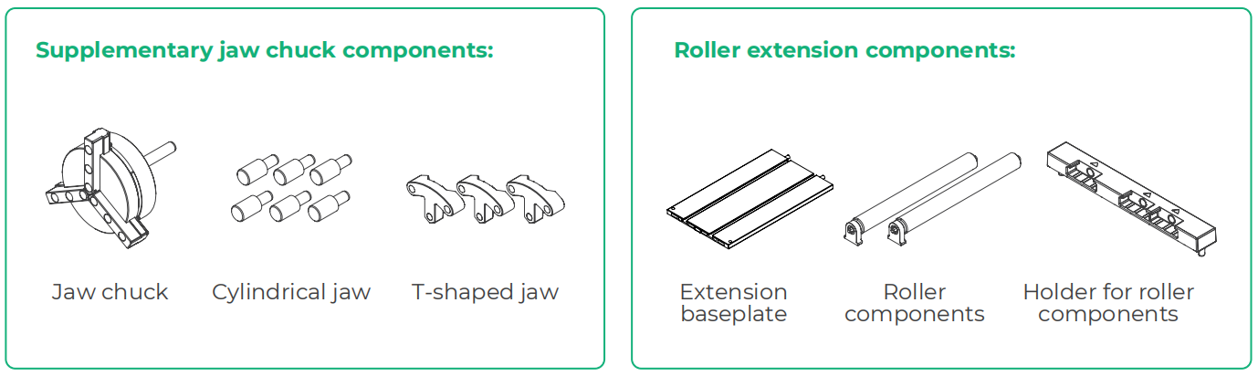
To process workpieces in batches, the following materials can be purchased separately.
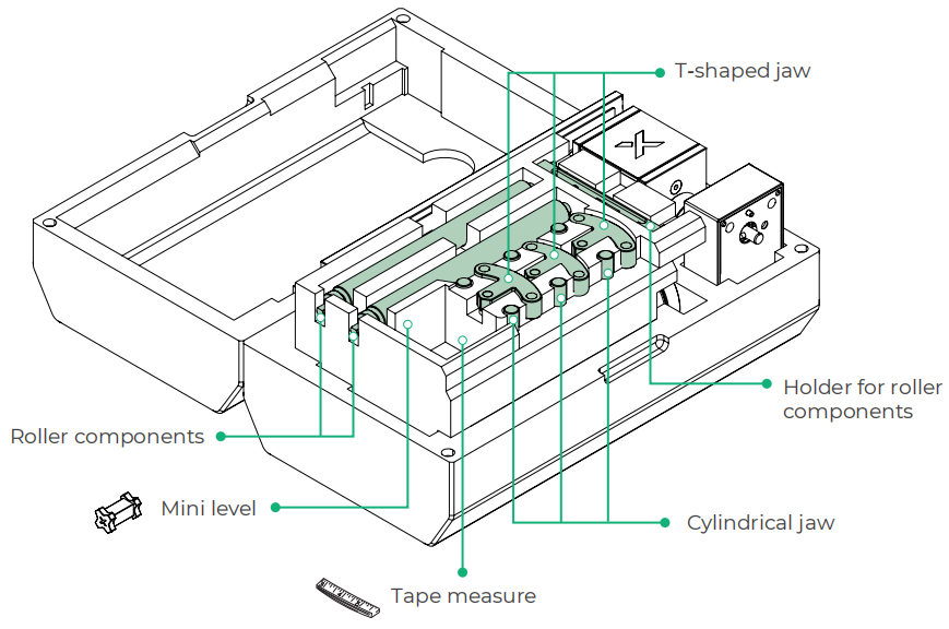
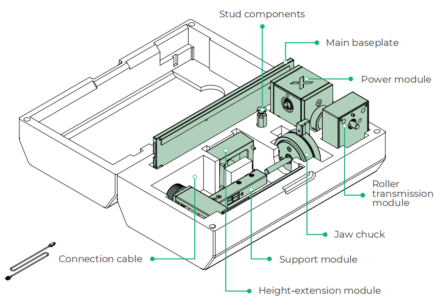
Storage box layout
Top layer
Bottom layer
Use xTool Rotary Attachment 3
Introduction to processing modes
Processing mode | Object to be processed | Assembly form | |
|---|---|---|---|
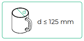
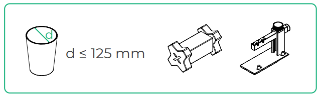
Jaw chuck mode (Suitable for processing cylindrical objects, spherical objects, and rings) | Cylindrical objects (5 mm ≤ d ≤ 95 mm, "d" stands for diameter) | Hold the workpiece using cylindrical jaws |
|
Large or smooth-surfaced cylindrical objects (55 mm ≤ d ≤ 125 mm) | Hold the workpiece using T-shaped and cylindrical jaws |
| |
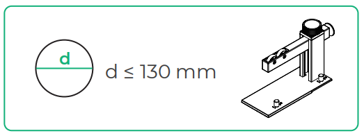
Large-volume cylindrical objects (55 mm ≤ d ≤ 130 mm), such as tumblers | Use the height-extension module |
| |
Cylindrical and spherical objects | Maintain the workpiece's position using the support module |
| |
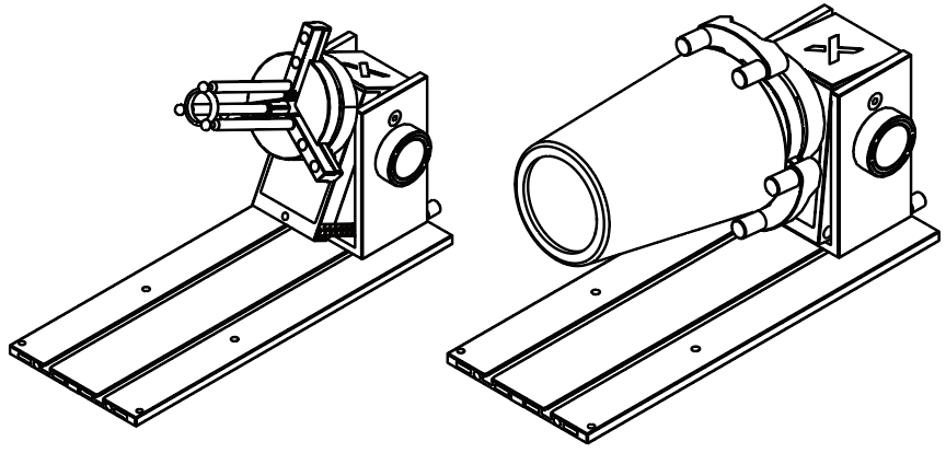
Rings and conical cups | Process the workpiece at an angle |
| |
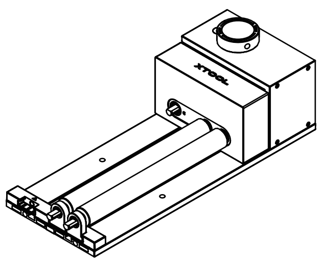
Roller mode (Suitable for processing cylindrical objects) | Cylindrical objects (5 mm ≤ d ≤ 45 mm) | Level S |
|
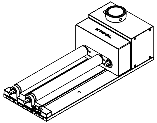
Cylindrical objects (40 mm ≤ d ≤ 70 mm) | Level M |
| |
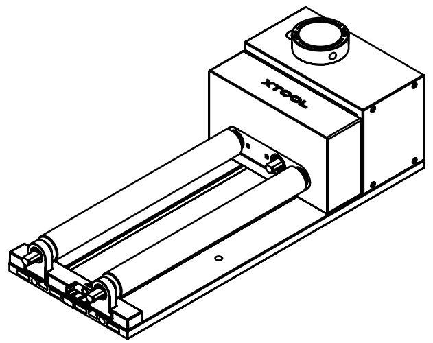
Cylindrical objects (60 mm ≤ d ≤ 100 mm) | Level L |
| |
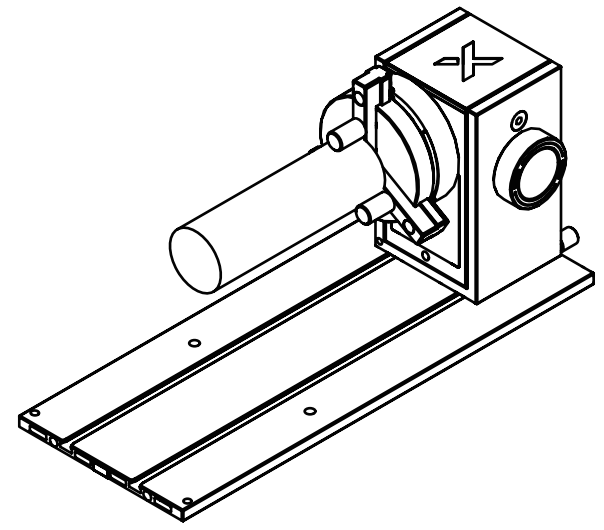
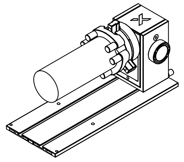
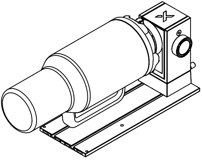
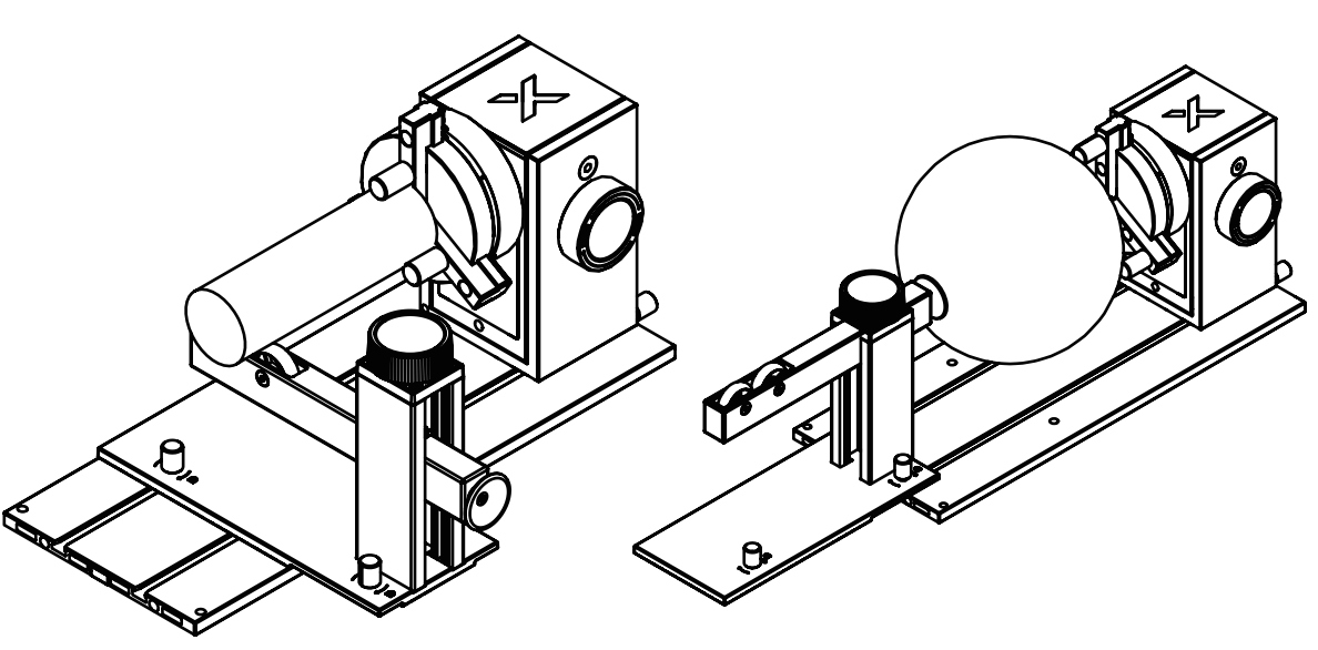
Jaw chuck mode
Preparations
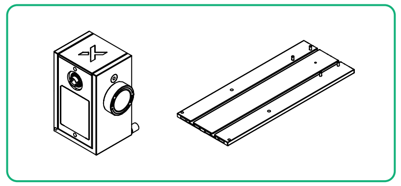
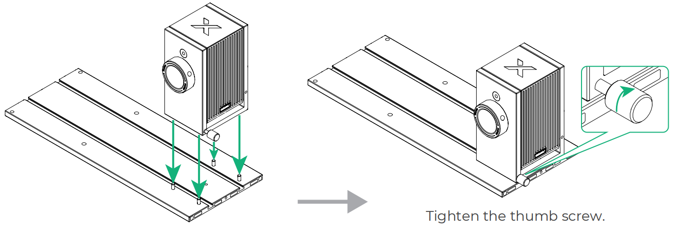
1. Fix the power module on the main baseplate.
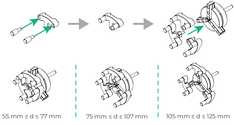
2. Assemble the jaw chuck components.
Method 1: Suitable for processing common cylindrical objects

Method 2: Suitable for processing large or smooth-surfaced cylindrical objects
Process cylindrical objects
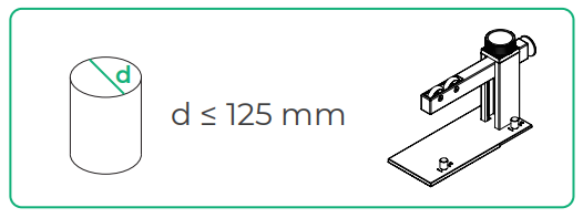
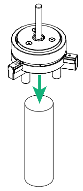
1. Put the workpiece on a table. Place the jaw chuck against the workpiece as illustrated, with its jaws surrounding the outside of the workpiece.
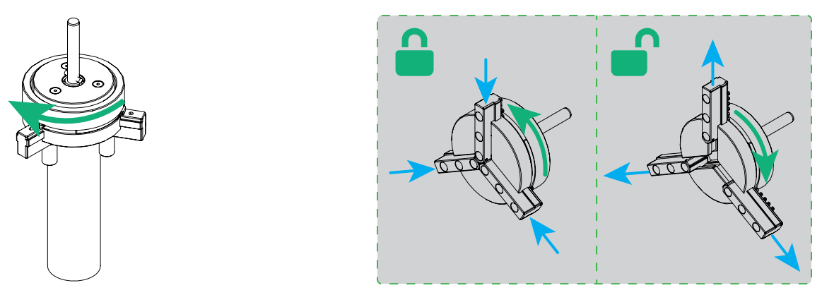
2. Rotate the knob to secure the workpiece.
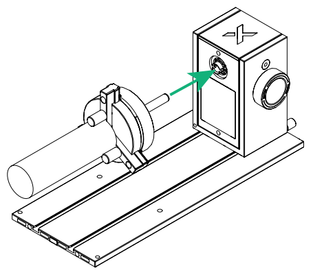
3. Insert the jaw chuck components into the power module.
4. Rotate the jaw chuck components until you hear a click.
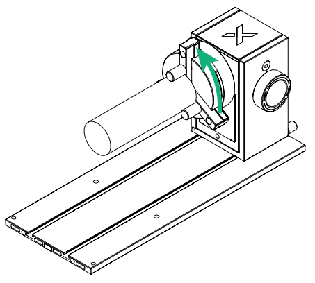
Note: To remove the jaw chuck from the power module, hold the jaw chuck firmly and pull it straight out.
5. Slide the support module into the main baseplate.
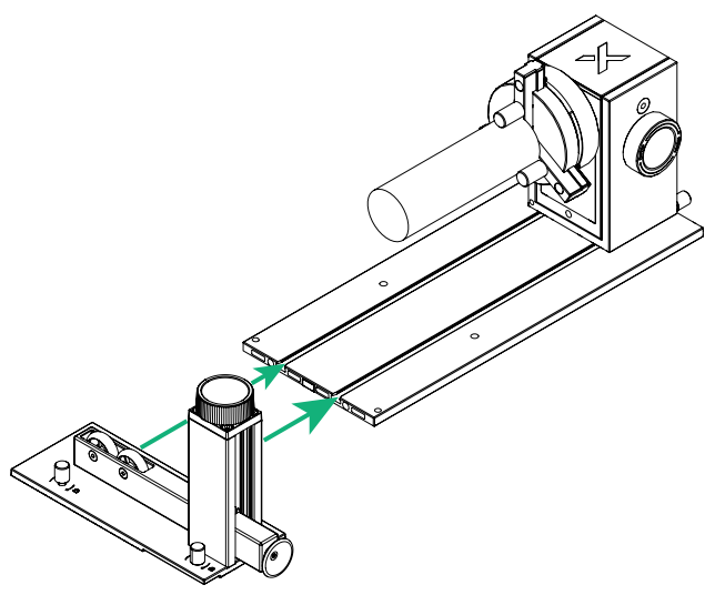
6. Rotate the knob clockwise to hold the support module in position.
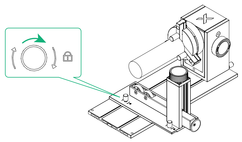
7. Rotate the knob to adjust the height of the two wheels on the support module until they touch the workpiece.
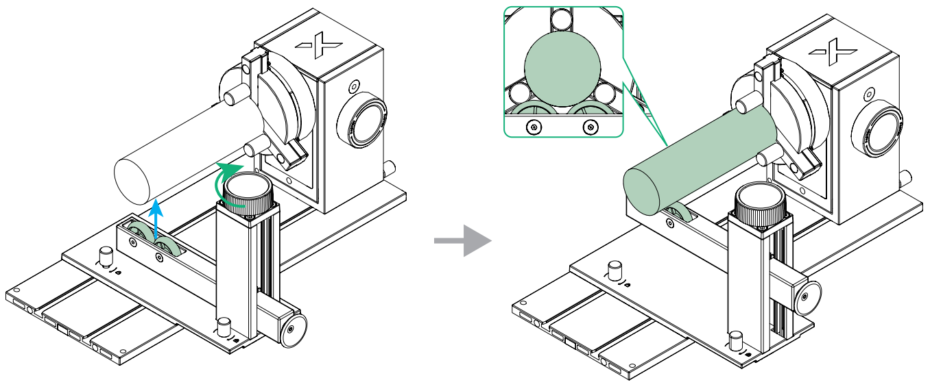
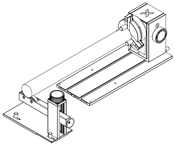
If the workpiece is long, there are two methods to use the support module.
Method 1: Slide the support module into the main baseplate and hold it in position
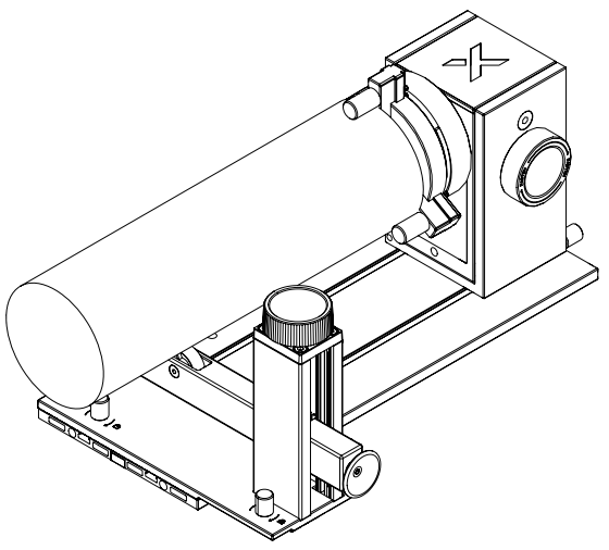
Method 2: Place the support module outside the main baseplate
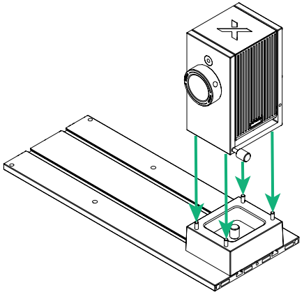
If the workpiece is large in volume, such as mugs and tumblers, you can use the height-extension module.
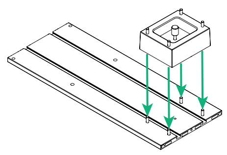
1. Install the height-extension module onto the main baseplate.
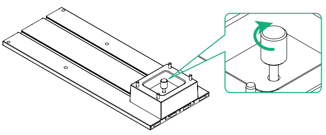
2. Tighten the thumb screw on the height-extension module.
3. Install the power module onto the height-extension module.
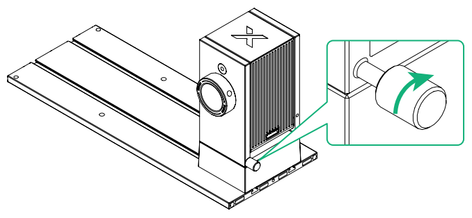
4. Tighten the thumb screw on the power module.
Process mugs
Before processing, ensure that the mug's handle does not touch the laser module when it rotates during processing. It is recommended that you place the mug with its handle facing downward.
1. Place the mug on a level table, and place the jaw chuck against the mug with the cylindrical jaws outside the mug. This external clamping method is suitable for processing cups with slippery outer walls and heavy weight, or inclined inner walls, such as mugs.
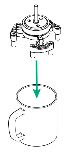
2. Rotate the knob on the jaw chuck to secure the mug.
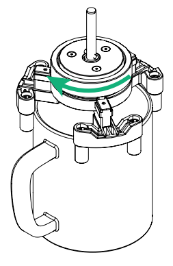
3. Insert the jaw chuck components into the power module.
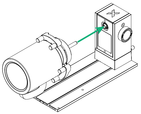
4. Rotate the jaw chuck components until you hear a click.
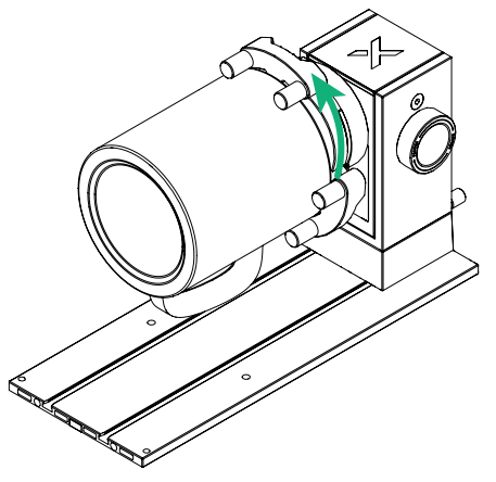
Note: To remove the jaw chuck from the power module, hold the jaw chuck firmly and pull it straight out.
Process tumblers
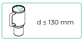
Before processing, ensure that the tumbler's handle does not touch the laser module when it rotates during processing. It is recommended that you place the tumbler with its handle facing downward.
1. Place the tumbler on a level table, and place the jaw chuck against the tumbler with the cylindrical jaws inside the tumbler. This internal clamping method is suitable for processing cups with rough outer walls, straight inner walls, and light weight, such as tumblers.
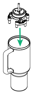
2. Rotate the knob on the jaw chuck to secure the tumbler.
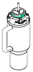
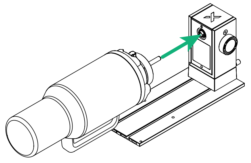
3. Insert the jaw chuck components into the power module.
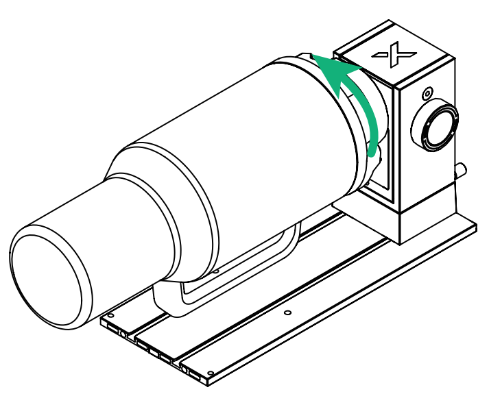
4. Rotate the jaw chuck components until you hear a click.
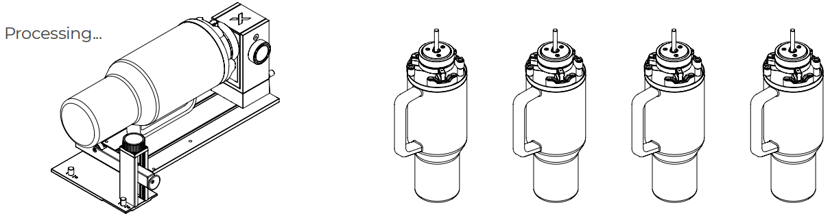
To process workpieces in batches, the supplementary jaw chuck components can be purchased separately.
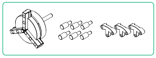
During processing, you may use the supplementary jaw chuck components (purchased separately) to prepare other workpieces for processing. After processing, remove the processed workpiece and jaw chuck components from the power module. Next, insert the jaw chuck components that are installed with a new workpiece into the power module. Rotate the jaw chuck components until you hear a click. You can now continue with the processing.
Note: To remove the jaw chuck from the power module, hold the jaw chuck firmly and pull it straight out.
Process spherical objects
1. Insert the assembled jaw chuck components into the power module.
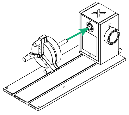
2. Rotate the jaw chuck components until you hear a click.
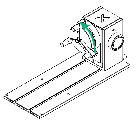
Note: To remove the jaw chuck from the power module, hold the jaw chuck firmly and pull it straight out.
3. Place one side of the workpiece against the jaws.
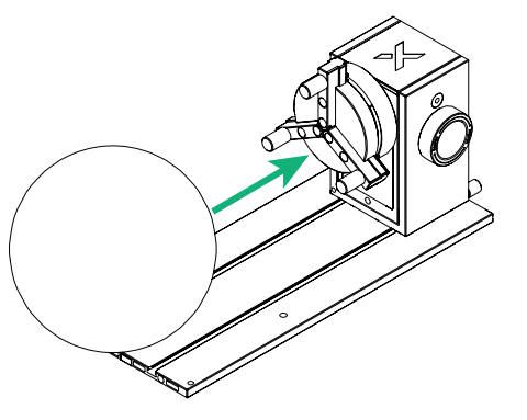
4. Slide the support module into the main baseplate, with its bell mouth against the other side of the workpiece.
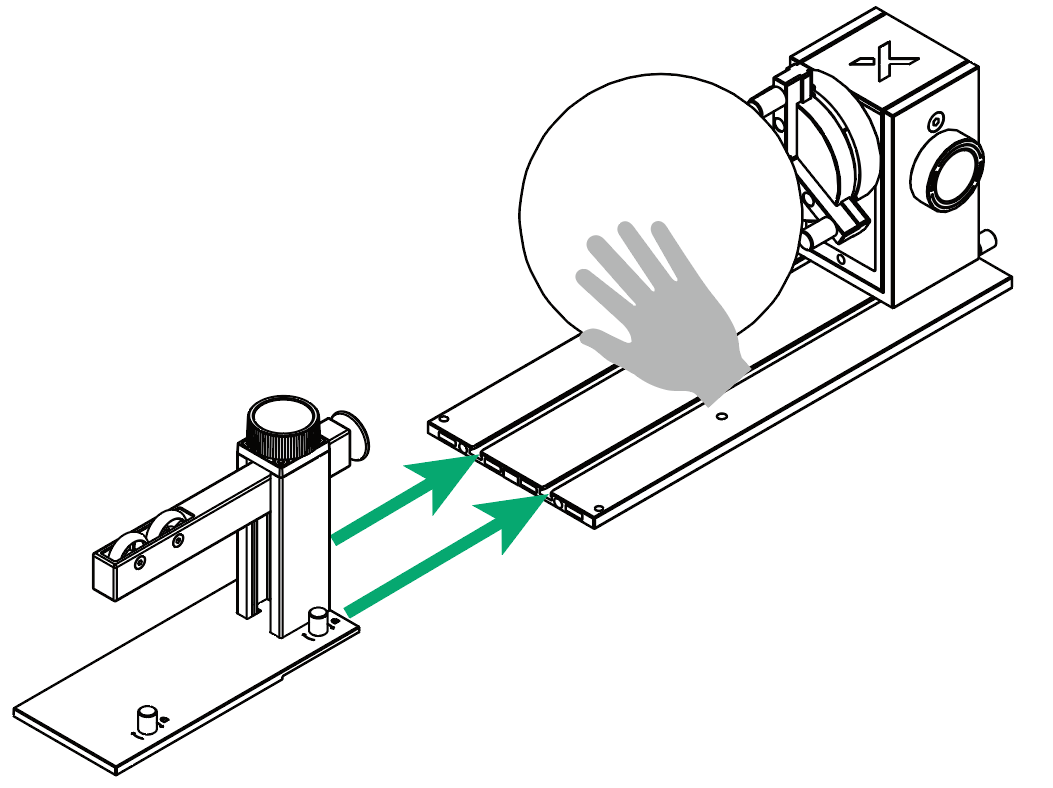
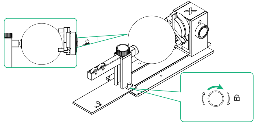
5. Rotate the knob clockwise to hold the support module in position.
Process rings
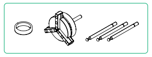
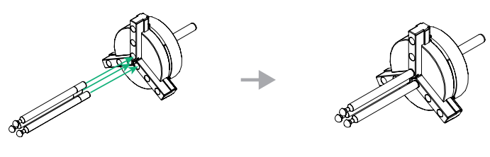
To process the outer surface of a ring, follow the steps below.
1. Place the ring onto the stud components.
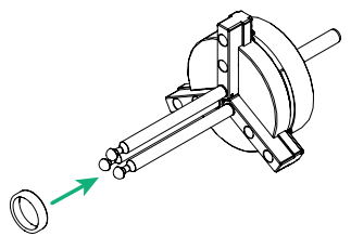
2. Rotate the knob to secure the ring.
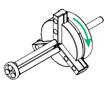
3. Insert the jaw chuck into the power module.
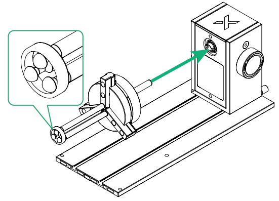
4. Rotate the jaw chuck until you hear a click.
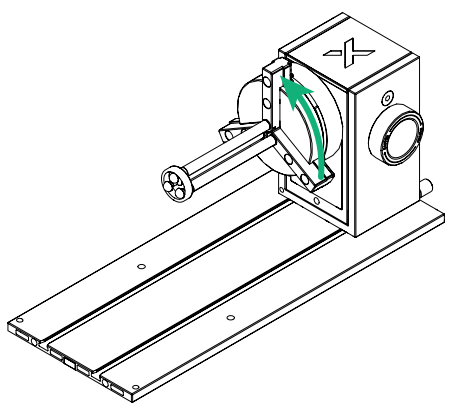
Note: To remove the jaw chuck from the power module, hold the jaw chuck firmly and pull it straight out.
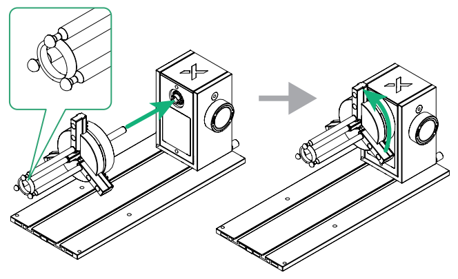
To process the inner surface of a ring, follow the steps below.
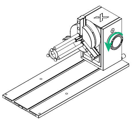
1. Rotate the knob on the jaw chuck.
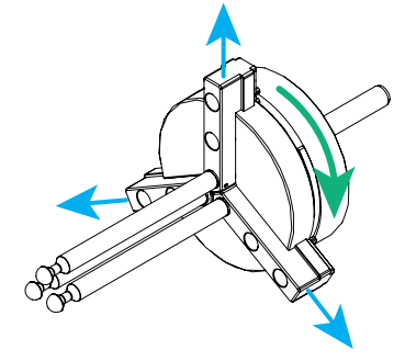
2. Hold the ring using the stud components, then rotate the knob to secure the ring.
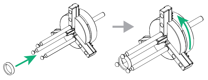
3. Insert the jaw chuck into the power module, then rotate the jaw chuck until you hear a click.
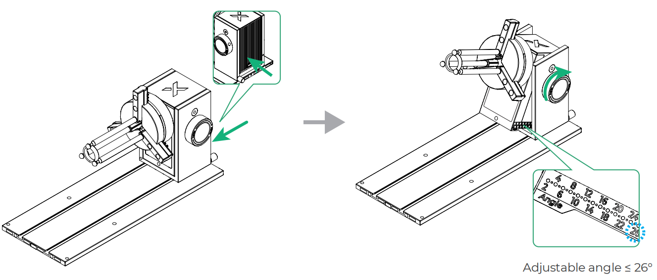
4. Rotate the side knob counterclockwise to unlock the angle adjustment function of the power module.
5. Adjust the angle of the power module to its maximum (26°), then rotate the knob clockwise to lock the angle.
Process other rotating objects
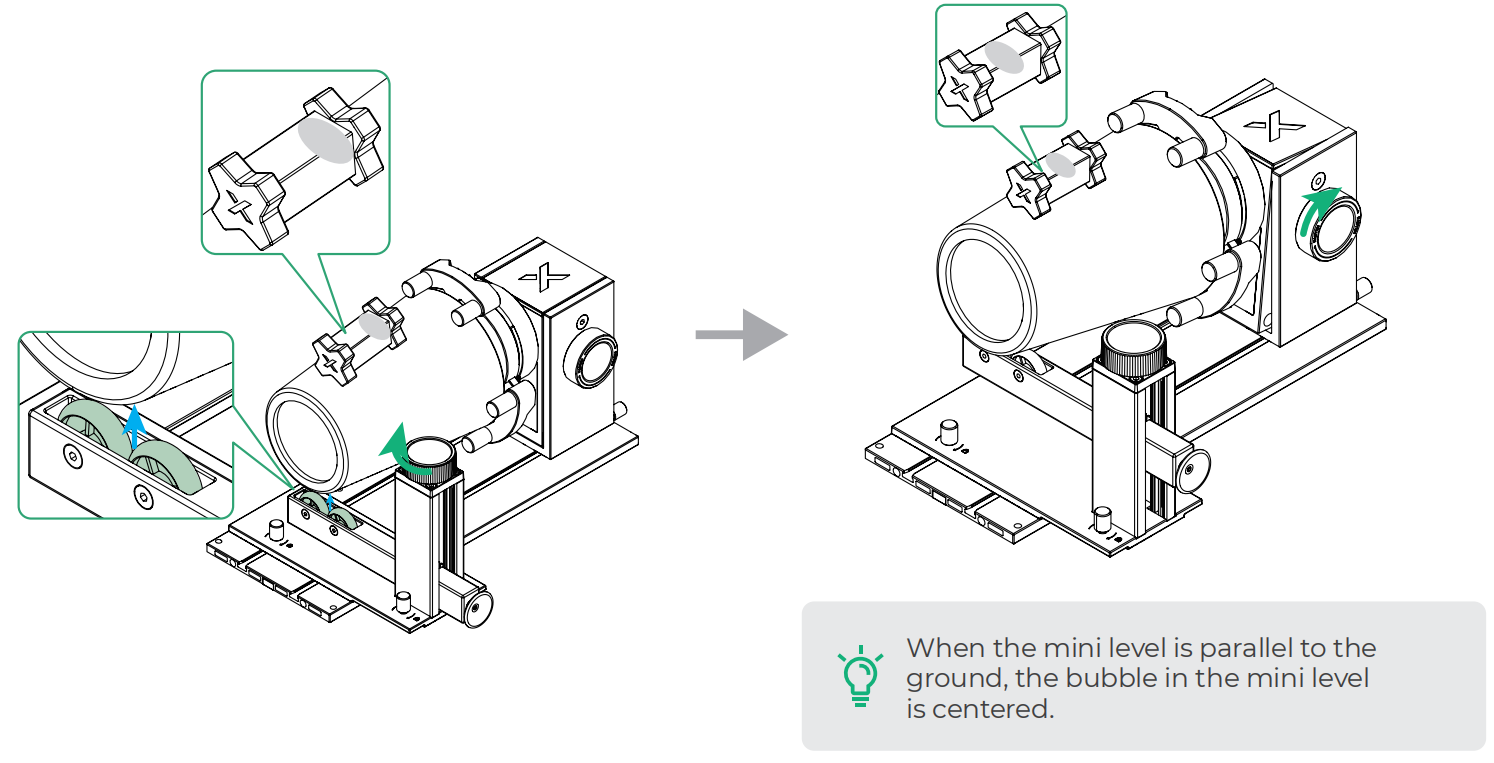
In manual mode, when dealing with a rotating object that has a regular inclined surface (such as a conical cup), you can use a mini level to ensure the surface to be processed is parallel to the ground before proceeding with the operation.
1. Place the conical cup inside the cylindrical jaws.
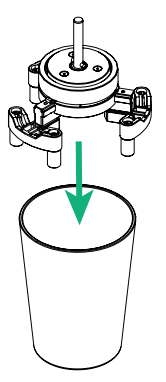
2. Rotate the knob on the jaw chuck to secure the conical cup.
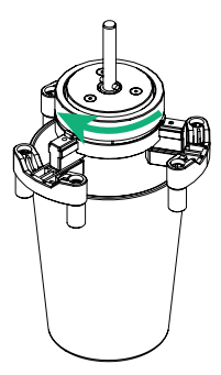
3. Insert the jaw chuck components into the power module.
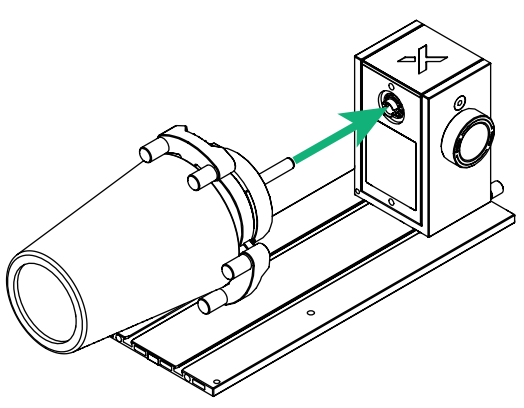
4. Rotate the jaw chuck components until you hear a click.
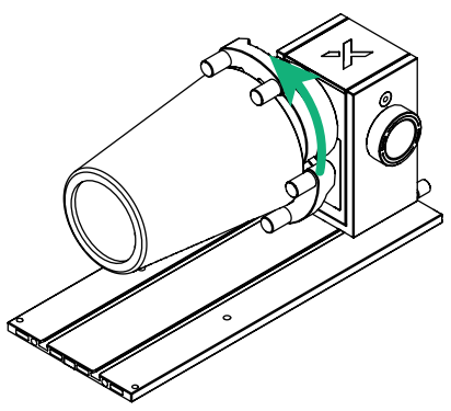
Note: To remove the jaw chuck from the power module, hold the jaw chuck firmly and pull it straight out.
5. Slide the support module into the main baseplate.
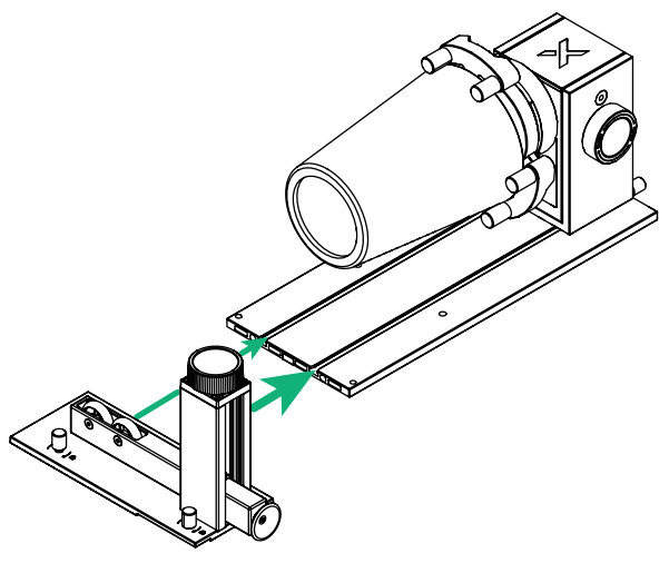
6. Rotate the knob clockwise to hold the support module in position.
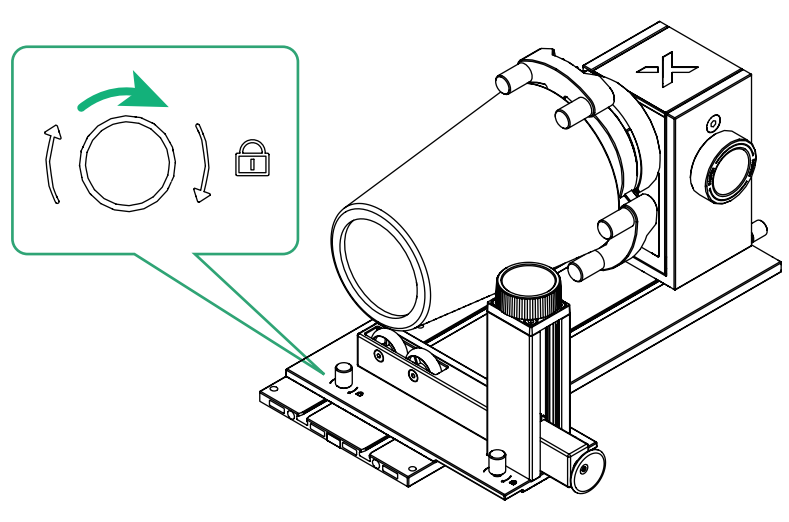
7. Place the mini level on the conical cup.
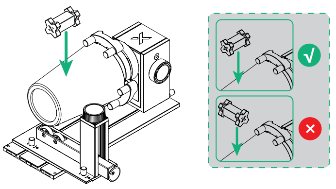
8. Rotate the side knob counterclockwise to unlock the angle adjustment function of the power module.
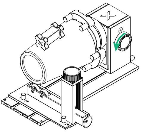
9. Rotate the knob to adjust the height of the two wheels on the support module until the mini level is parallel to the ground. Next, rotate the knob clockwise to lock the angle.
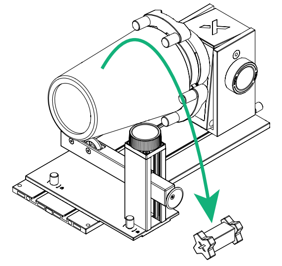
10. Remove the mini level from the conical cup.
Roller mode

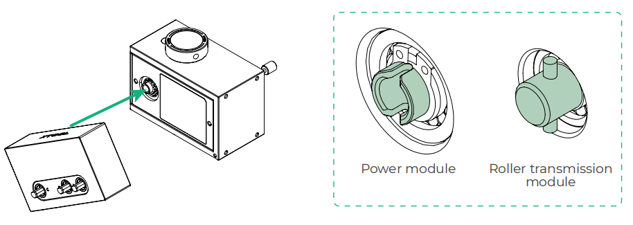
1. Insert the roller transmission module into the power module, aligning the highlighted parts.
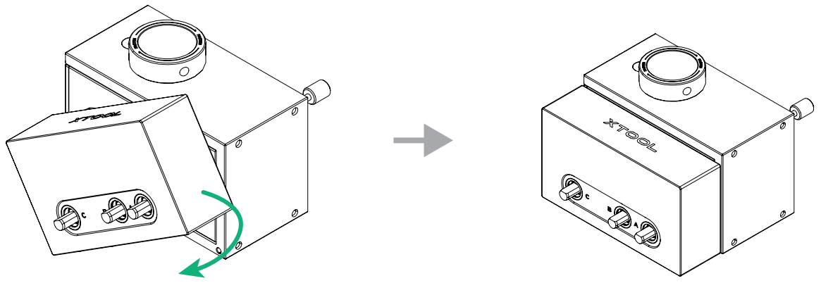
2. Rotate the roller transmission module until its bottom edge is parallel to the bottom edge of the power module.
3. Place the power module and the roller transmission module on the main baseplate.
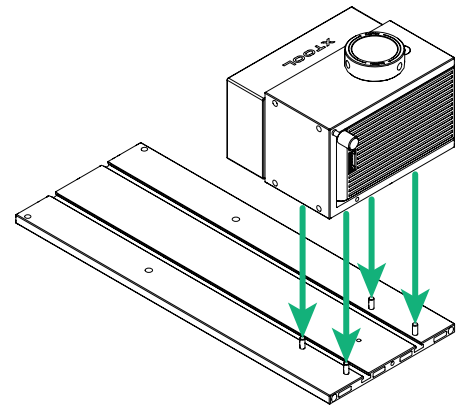
4. Unscrew the thumb screw.
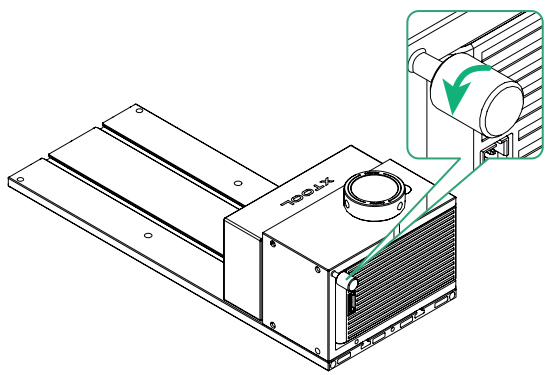
5. Screw the unscrewed thumb screw into another hole in the power module.
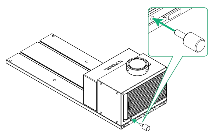
6. Tighten the thumb screw.
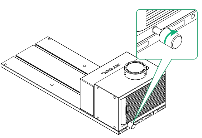
7. Place the holder for roller components on the main baseplate. Pay attention to the direction.
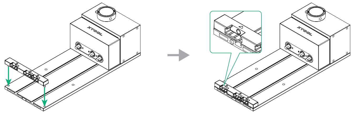
8. Install the roller components onto shaft A on the roller transmission module.
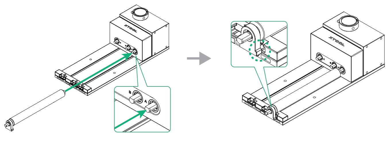
9. Rotate the roller until it is installed onto shaft A. Ensure that both ends of the roller components are properly installed.
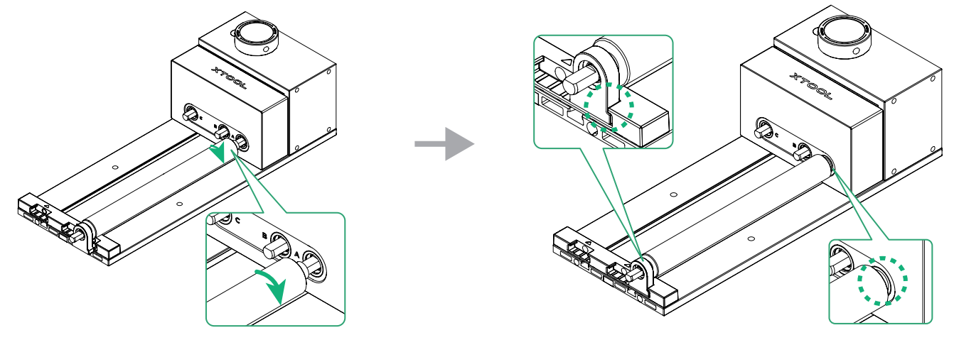
10. Install the other roller components in the same way. Here are three scenarios depending on the workpiece's diameter.
Scenario 1: Level S (roller components installed onto shaft A and shaft B) | Scenario 2: Level M (roller components installed onto shaft B and shaft C) | Scenario 3: Level L (roller components installed onto shaft A and shaft C) |
|---|---|---|
|
|
|
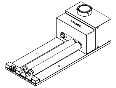
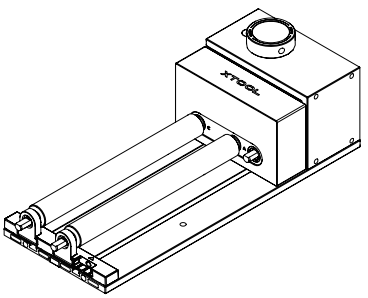
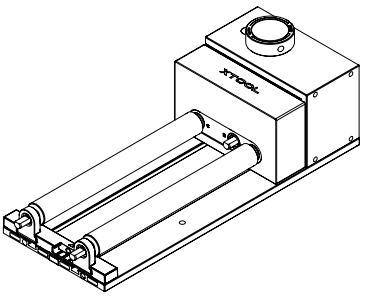
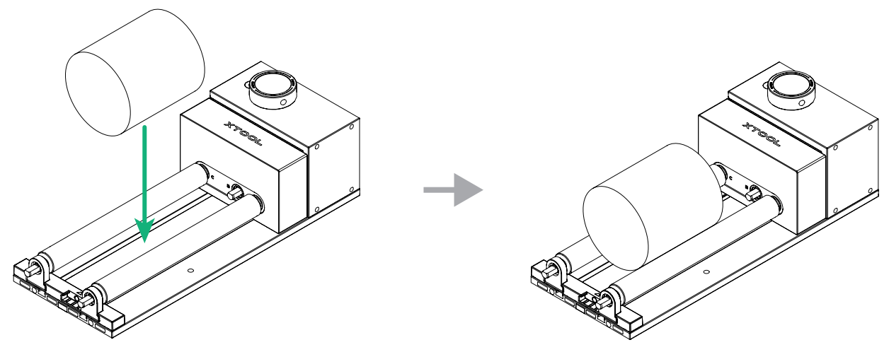
11. Place the workpiece between the two rollers.
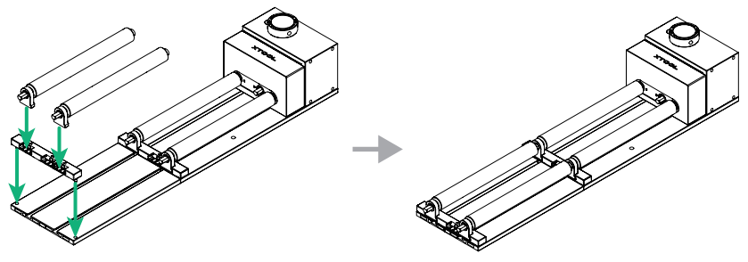
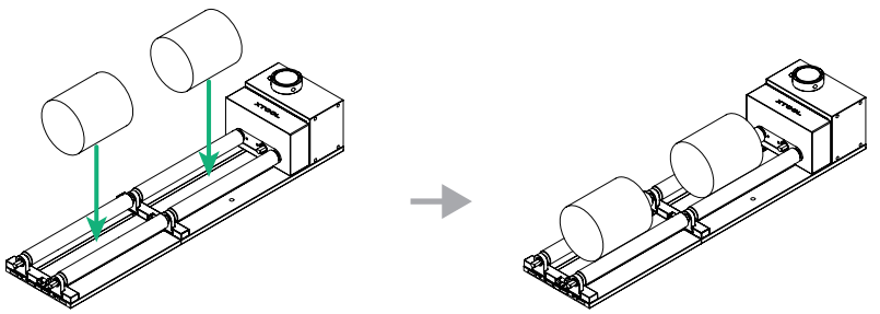
To process objects in batches, the roller extension components can be purchased separately.

1. Insert the extension baseplate into the main baseplate.
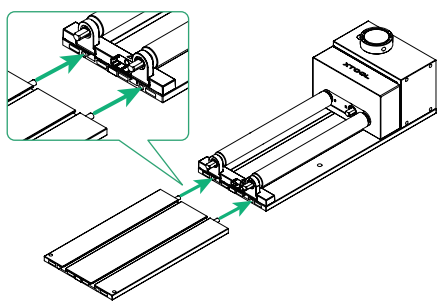
2. Refer to the earlier instructions to install the holder for roller components and the roller components.
3. Place the workpieces between the rollers.
Maintenance
- Clean the product using a dry cloth.
- Keep the product in the storage box when it is not in use.
- The product features a magnetic quick-release design. The moving joints are prone to wear and rust. Apply rust‑preventive oil regularly and keep the product dry and clean.
FAQ
Q: The thumb screw is bent or deformed. What should I do?
A: Contact our after-sales services at support@info.xtool.com.