⚠️ Important warnings
- Irreversible Action: This manual calibration process modifies the underlying system data of the camera. Once completed, the original data cannot be restored. Proceed with caution.
- Consult Support First: If you are unsure whether your xTool M1 requires this specific calibration, please contact xTool Customer Service at support@xtool.com. Include a video demonstrating the positioning error for assessment before proceeding.
About positioning errors
Slight discrepancies in camera positioning are normal due to current technological limitations. These errors may be ascribed to the materials' location, material surface flatness, and processing scenarios.
For tips on minimizing these errors during standard use, refer to: How to Ensure the Image Positioning Accuracy of xTool M1
Prerequisite: Assess the error
Before performing a manual calibration, follow these steps to determine if the error is within acceptable limits.
- Prepare Material: Place a 3mm flat material (e.g., basswood plywood) on the baseplate.
- Set Mode: In xTool Creative Space (XCS), set the processing mode to Process on baseplate (formerly "Laser flat" in v1.x versions).
- Process: Select the Score function, create a simple shape, and process the material.
- Verify: After processing is complete, click the Refresh button in XCS.
- Measure: Compare the actual scored pattern on the material against the position shown on the screen.
- Acceptable Tolerance: A discrepancy of ≤ 1.5mm in the central processing area (at a height of 3mm) is considered normal.
💡 Note on Accuracy Factors:
- Vertical Distance: Accuracy decreases as the vertical distance between the camera and the material increases (for example, if the material is placed at a higher position).
- Horizontal Distance: Accuracy decreases the further the object is placed from the center of the camera's field of view (fisheye effect; for example, if the material is placed at the edge of the camera’s field of view rather than in the center).

After the manual camera calibration is complete, please calibrate the auto-measure to avoid significant measurement results.
- How to Calibrate the Auto-Measure for xTool M1
Application scenarios
Perform this calibration only if you are experiencing the following issues:
- Significant positioning errors in xTool M1 camera that exceed the tolerance mentioned above.
- The camera image appears significantly deformed in "Process on baseplate" mode (previously known as “laser flat” mode in XCS version 1.0 ).
- The camera fails to refresh due to a missing calibration file.
Tools required
Hardware & materials
- Computer: Windows 10 or later (Mac OS is not supported).
- Paper: Several sheets of A3 (297mm × 420mm) blank white paper.
- Tape: Transparent or white tape.
- Flat Material: One sheet of A3-sized (297mm × 420mm) or two sheets of A4-sized (210mm × 297mm) material.
- Requirement: Must be 3mm thick and perfectly flat (e.g., acrylic sheets).
- Note: Since the material's flatness will affect the camera positioning accuracy, it is advisable to ensure the material is as even as possible. Otherwise, the expected calibration effect will not be achieved.
Software
- Calibration Tool: xTool M1 First Calib
Calibration procedure
Step 1: Install software
Download and extract the calibration software.
- Important: Extract the software to a disk drive other than the C: drive (e.g., D: or E: drive). Some system permissions may block the software if run from the C: drive.
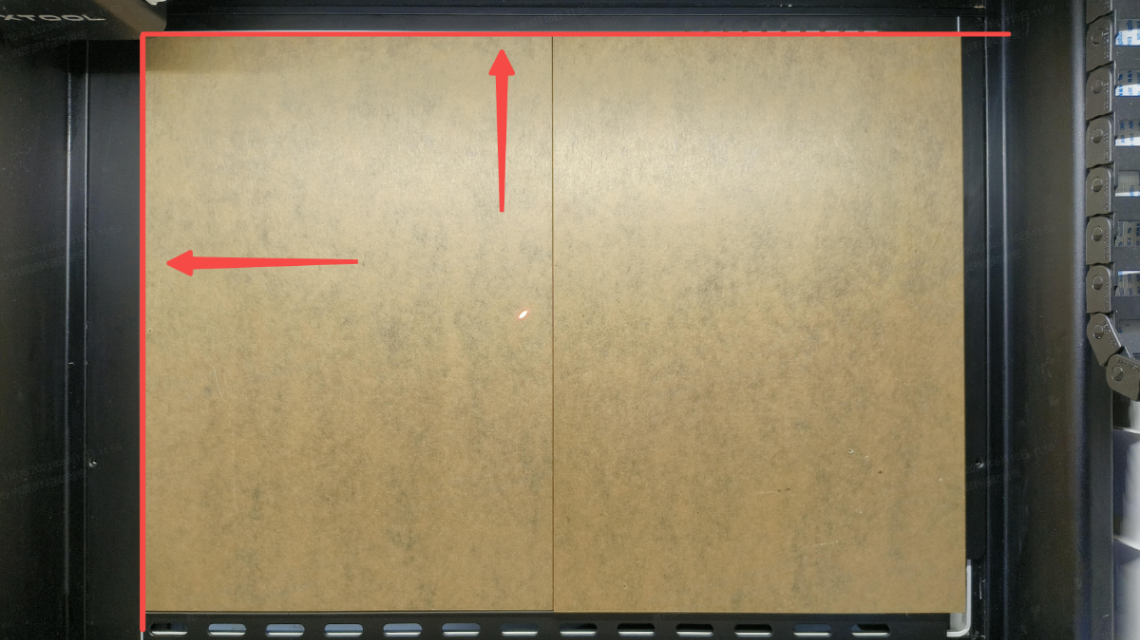
Step 2: Position the material
- Place two 3mm A4-sized acrylic boards or one 3mm A3-sized acrylic board with even surfaces on the baseplate.
- Align them along the red indication line as shown in the reference image.
Step 3: Secure the paper
Tape one sheet of A3 blank paper securely onto the acrylic board(s).
- Ensure the paper is spread completely flat with no wrinkles or raised edges.
Step 4: Connect the device
Close the xTool M1 lid and connect the laser device to your computer via USB cable.

Step 5: Launch software
Run the FirstCorrect_GUI.exe software.
- Troubleshooting: If the software fails to open, right-click the icon and select "Run as Administrator".
Step 6: Connect
Click the Connect button in the software interface.
Step 7: Process the calibration pattern
Click Process to engrave the calibration grid.
Critical Instructions for this Step:
- Do NOT press the physical start button on your laser device. This process is initiated entirely by the software.
- Disable Air Assist: Turn off the Air Assist Set and Smoke Purifier (if equipped). Airflow may move the paper, ruining the calibration.
- Do NOT open the lid during processing.
- If the lid is opened or the physical button is pressed by mistake, restart xTool M1 and begin the calibration procedure again.
💡 Usually, the exhaust fan of your laser device is automatically deactivated to prevent paper from being blown away, which could disrupt the calibration process.
Step 8: Capture image
Once processing is complete, click Snapshot to capture an image of the grid.
- Note: If the internal LED lights have turned off, open and close the lid to reactivate them, before clicking Snapshot again.
Step 9: Generate calibration file
Click Generate. The software will analyze the grid.
Step 10: Analyze results
Inspect the calibration grid displayed on the screen:
- 🔴 Red Circles: Indicates significant deviation. Calibration Failed. You must repeat the procedure from the beginning.
- 🟡 Yellow Circles: Indicates minor deviation. Check for grid deformation.
- < 20 Yellow Circles (No deformation): Pass. Proceed to Step 11.
- > 20 Yellow Circles (Visible deformation): Fail. You must repeat the procedure.
Step 11: Upload data
If the results are acceptable, click Update to upload the new calibration file to the machine. Once the upload is complete, close the pop-up window.
Step 12: Verify & finalize
- Return to xTool Creative Space (XCS).
- Repeat the Prerequisite test (Score a shape on 3mm material) to verify accuracy.
- If the test result falls short of the expectation, please recalibrate.
- Important Final Step: If the camera accuracy is now satisfactory, you must recalibrate the Auto-measure function.
Still experiencing issues?
Should the issue persist after completing the preceding steps, submit a ticket via the "Submit a Ticket" button in the "Help Ticket" section below. The standard response time for xTool Customer Service is one business day.
For a prompt resolution, please include the following details:
- Issue description: A detailed explanation of the observed problem.
- Video evidence: Attach a video demonstrating the issue, where applicable.
- Troubleshooting performed: Any troubleshooting steps you have already attempted, along with their results.
This information is crucial for xTool technical support engineers to provide timely assistance.
Documentation feedback
Help improve this content by providing feedback. If this content did not meet your requirements, select "No" in the "Was this page helpful?" section below. Include specific details about what was unclear or missing in the pop-up suggestion box. Feedback submissions are reviewed by xTool technical writers to enhance future documentation.
Services & Help
Learn & Education

Copyright © 2025 xTool All Rights Reserved.