This page describes the functions of xTool Creative Space (XCS) and how to use it to operate xTool D1 Pro.
Minimum and recommended PC requirements
4. Open a project file, import an image, or create your design on XCS
5. Set the processing type, mode, and parameters
- Shortcut keys
- Right-click menus
- Menus
- Project name
- Links
- Tools
- Canvas
- Canvas management
- Device settings
- Processing settings
- Start processing
Minimum and recommended PC requirements
| Item | Minimum configuration | Recommended configuration |
| Processor | Intel Core i5-6200U | Intel Core i5-11600 |
| Operating system | Win 10 (64 bit) macOS 10.14 or later | |
| RAM | 8 GB | 16 GB |
| Display resolution | 1280 × 720 (pixels) | 1920 × 1080 (pixels) or higher |
| Hard drive | 8 GB | 12 GB |
- With the minimum configurations, all the functions of XCS can be used properly. When you import a complex image, such as an image larger than 50,000,000 pixels or an SVG image larger than 1 MB, however, XCS may fail to run smoothly.
- With the recommended configurations, XCS can run more smoothly when you import and edit a complex image, the software delay may be shorter, and the performance is better.
Download and install XCS
(1) Download the xTool Creative Space software (https://www.xtool.com/pages/software) applicable to the operating system that runs on your PC.
Click Yes when you are asked "Do you want to allow this app to make changes to your device?" and then continue the installation as prompted.
Quick start example
1. Select a language
2. Connect xTool D1 Pro to XCS
3. Place a material
4. Create a new project, open a project file, import an image, or create your design on XCS
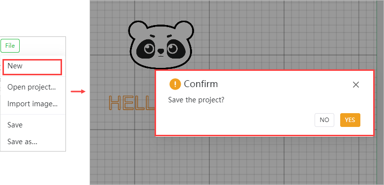
Create a new project
Click New to create a new project. Confirm whether to save the previous project or not.
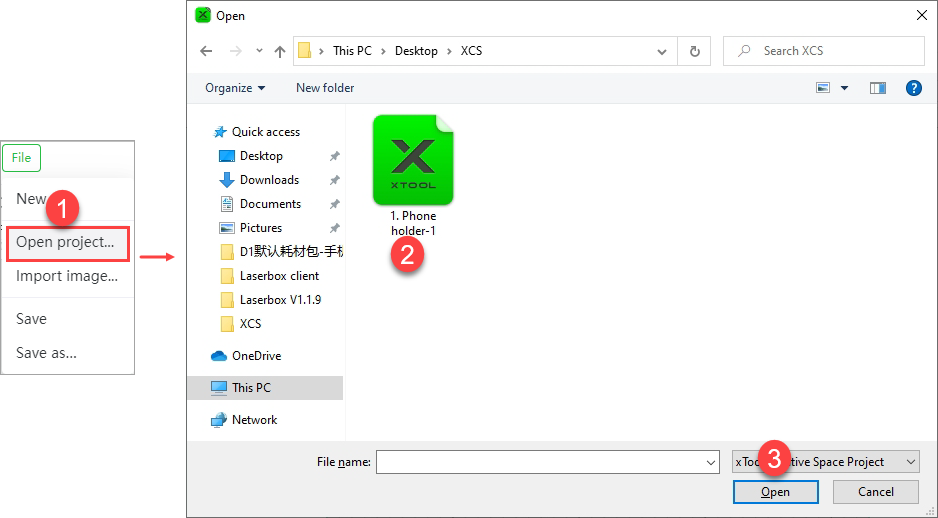
- Open a project file (supporting only .xcs files)
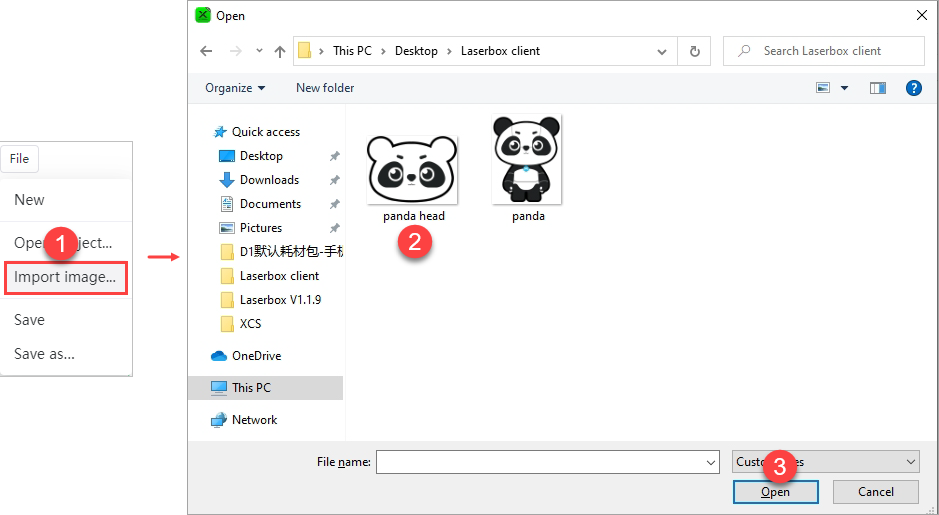
- Import an image. Currently, XCS supports the importing of only JPG, JPEG, GIF, PNG, BMP, SVG, DXF, and WEBP files.
After importing an image, you can directly use the image or edit it to make your own design.
- Create your design
You can insert a shape, enter a text, or draw vector paths on the canvas.
Note: Currently, the text elements contained in SVG files are not supported when XCS imports SVG. If you want to design the text in the design software and import it, you need to convert the text into a vector graphic path in the design software. And then export SVG to be properly parsed in XCS.
5. Set the processing type, mode, and parameters
Select each design element and set the processing type, mode, and parameters for it.
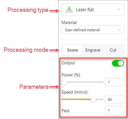
Note: For user-defined materials, you can set the power, speed, and pass parameters according to the settings recommended in the user manual.
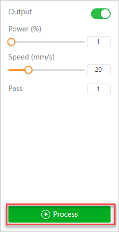
6. Start processing
Click Process to start processing.
The Preview window is as follows.
Click Framing to preview whether the design elements are to be processed as expected in the expected area. If yes, click Start to start the processing. You can click Cancel to cancel the processing.
In processing, you can pause and continue the processing by clicking Pause and Continue on XCS or by pressing the button on the device.
To cancel the processing, click Cancel.
This is the general process of using XCS to create your works. For details of the functions of XCS, see Function description.
Function description
Note:
When you use XCS, some functions may be unavailable in some scenarios, displayed in gray. This is what it is supposed to be. These functions are described as follows:
- Smart fill
This function is available only after you have connected your device to XCS. Note that this function is supported only for machines with cameras, such as xTool M1. Machines without cameras, such as the xTool D series, do not provide this function.
Align
This function is available only after you have selected two or more design elements.
Combine
This function is available only for vector elements and can be used only after you have selected two vector elements.
Menus
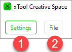
① Settings
General
- Unit: sets the unit for displaying the size and position of a design element
- Auto-snapping: enables or disables the auto-snapping function of the canvas. The function is enabled by default.
- When it is enabled, guides appear when you move an element on the canvas to help you align the element with another element or the grids.
-
- When it is disabled, no guide appears when you move an element.
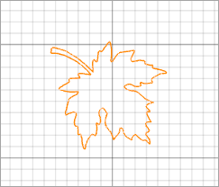
- Precise vector path selection: By default, this function is disabled.
When this function is disabled, you can select a vector path by clicking on the selection box of it. The selections boxes of multiple vector paths, however, may overlap, causing difficulty in selecting the target vector path.
As shown in the following figure, it is difficult to select the purple line because it is located within the selection box of another line.
When this function is enabled, no selection box is provided for vector paths. You need to move the mouse pointer close to a line to select it. In this way, you can select a vector path without selection box interfering.
As shown in the following figure, you can select a line by moving the mouse pointer close to it and then clicking.
- Imported image too large for the canvas: sets how to process an imported image that is too large for the canvas, including the following options:
- Ask me every time: XCS asks you every time when you import an image that is too large for the canvas.
-
- Auto-scale it: XCS automatically scales an image that is too large for the canvas when you import it.
-
- Keep its size: XCS displays an image that is too large for the canvas in the original size when you import it.
- Hot keys: You can click View to view all the hot keys supported by XCS.
- Language: sets the language of the UIs
- Software update: displays the software version and checks for later versions
- About: displays information about the software
Developer mode
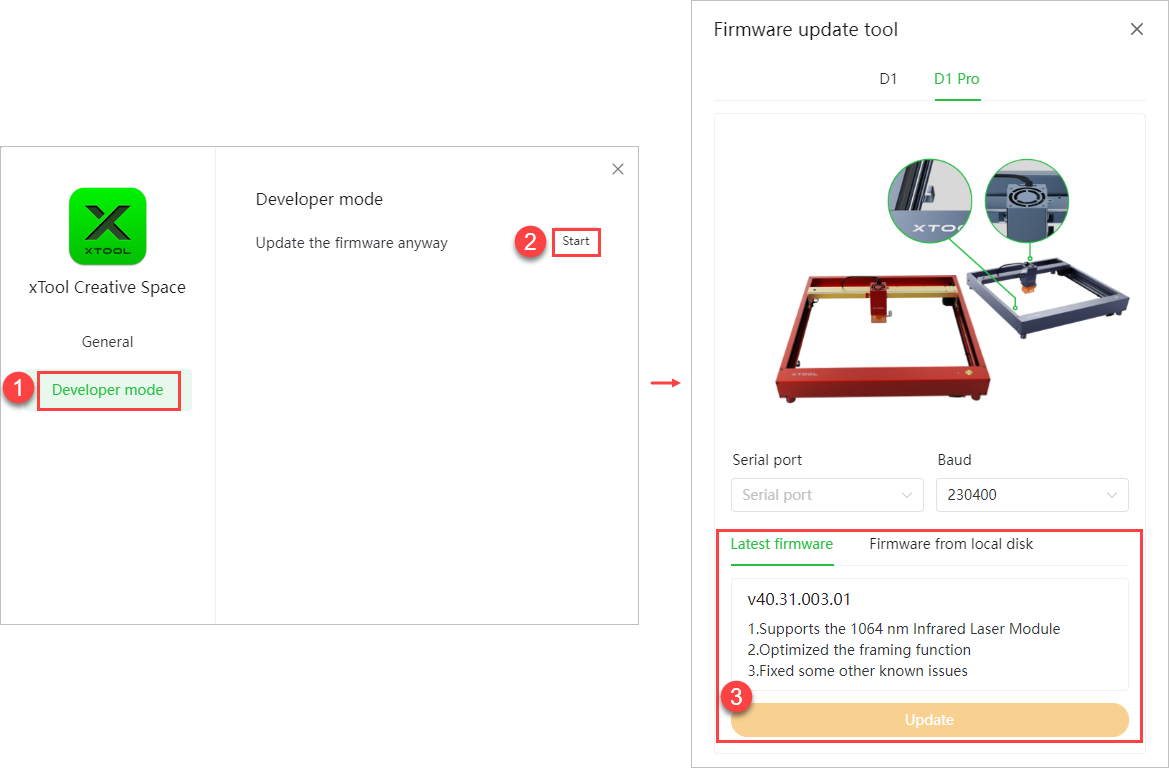
Update the firmware anyway: Click Start to start the firmware upgrade function and click Update to update the latest firmware.

Or you can select Firmware from local disk, and select or drag the firmware to update.
② File
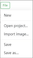
- New: creates a new project
- Open project: opens a local project file, supporting only .xcs files
- Import image: import an image file. Currently, XCS supports the importing of onlyJPG, JPEG, GIF, PNG, BMP, SVG, DXF, and WEBP files.
- Save: saves all the changes to the project
- Save as: saves the project to another file
Project name
It displays the name of the project.

Links
- Announcement: links to the announcement window of XCS, where you can find the latest announcement released
- Community: links to the XCS community, where you can find more information about XCS, share your projects, discuss with others, and get inspired
- Projects: links to the example project center, where you can find various example projects
- Support: links to the xTool support website, where you can find online help for xTool products
- Shop: links to the xTool online store, where you can purchase xTool products, accessories, and materials
Tools
Vertical toolbar
|
- Image: click to image an image. Currently, XCS supports the importing of only JPG, JPEG, GIF, PNG, BMP, SVG, DXF, and WEBP files.
Note: Currently, text objects can't be properly parsed on XCS. If you are to import an SVG file including texts, please convert the texts into paths and then import the SVG file into XCS, so that the SVG image can be properly processed.
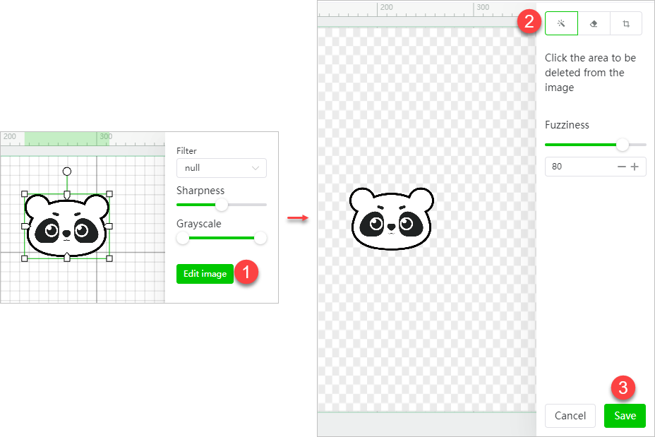
If you import a bitmap image, you can set it by using the image setting panel on the right after importing it.
-
- Filter: You can add a grid filter for the image.
-
- Sharpness: With other settings unchanged, sharpness is related to the clarity of detail in an image.
-
- Grayscale: The grayscale is related to the contrast of light and shade. Slide the block on the left to the middle to enhance the shade. Slide the block on the right to the middle to enhance the light.
-
- Invert:You can invert the colors of a bitmap image. This function can be useful for the processing of some dark materials, such as engraving bitmap images on transparent or translucent acrylic, black slates, ruber, and mirrors. The engraving results can be improved by using this function.
XCS supports color inverting of black-and-white, grayscale, and color bitmap images, as described in the following:- Black-and-white images: White pixels are inverted into black ones, and black ones are inverted into white ones.
- Invert:You can invert the colors of a bitmap image. This function can be useful for the processing of some dark materials, such as engraving bitmap images on transparent or translucent acrylic, black slates, ruber, and mirrors. The engraving results can be improved by using this function.
-
-
- Grayscale images: Light pixels are inverted into dark ones, and dark ones are inverted into light ones.
-
-
-
- Color images: A color image is converted into a grayscale image first, and then light pixels are inverted into dark ones, and dark ones are inverted into light ones.
-
Note: For an image with a transparent or translucent background, the background is not inverted, and only the colors of the pixels in the image are inverted.
In addition to the preceding settings, you can further edit an image.
-
- Magic wand: deletes the area you want to delete from the image
Fuzziness: This parameter is available only for the magic wind, indicating the range of pixel colors you delete at a time. The larger the value, the wider the color range, that is, the colors of the pixels to be deleted can be quite different; the smaller the value, the narrower the color range, that is, the colors of the pixels to be deleted are very similar.
-
- Eraser: erases the area where you click from the image
Size: This parameter is available only for the eraser, indicating the size of the eraser. The larger the value, the larger the eraser.
-
- Crop: keeps the area you select
- Insert: selected to draw a common shape. You can press Shift to draw a square, circle, or horizontal or vertical line.
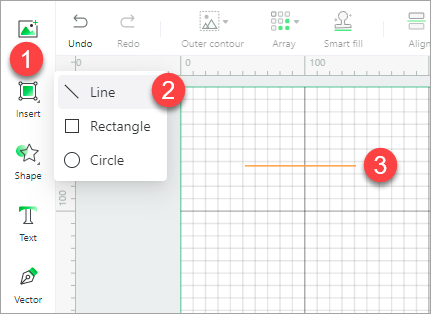
- Shape: inserts a shape
- Text: inserts a text. The default text is HELLO. After inserting the text, you can change the words, and set the font size, typeface, style, spacing, leading and aligning mode. In addition, you can weld the character strings in a text.
Weld
This function is used to unite the character strings that overlap one another partially in a text. After being welded, the text becomes vector paths and the text setting panel is not displayed after you select it.
If no character strings overlap one another partially in the text, the text looks the same but becomes vector paths after you weld it, and the text setting panel is not displayed after you select it.
- Vector: selected to draw a vector path. Press Esc to stop drawing.
You can press the Esc key or click any other menu to finish the drawing.
After drawing a vector path, you can double-click an anchor point to edit:
-
- convert it to a rounded corner or back to a corner
- adjust the curvature
- Select: selects one or more items
- Select one element: click an item to select it
- Select multiple elements:
- Way 1: drag the mouse pointer over all the elements to be selected
- Way 2: hold down the Shift key on the keyboard and click the elements to be selected. When holding down the Shift key, you can click an element again to deselect it
Note: When multiple elements are of the same type, you can set processing parameters for them at a time. But for those of different types, you need to set processing parameters for them separately.
- Hand: selected to move the canvas by dragging the mouse.
Horizontal toolbar
|
|
- Undo: cancels the last action
- Redo: performs the last action again
- Outline: adds an outline to the elements. In addition to adding outlines for bitmaps, vector paths, and texts, you can add inner outlines for bitmaps with transparent backgrounds.
If the background of a bitmap image is not transparent, when the offset distance is a positive value, the outline is outer. When the offset distance ia s negative value, the outline is inner.
If the background of a bitmap image is transparent, you can select Add inner outline for bitmap to add an inner and outer outline for it.
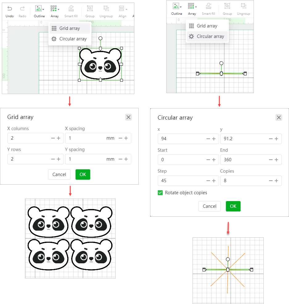
- Array: creates multiple copies of an element at a time and lays them out in grid or circular mode. Select an element, choose an array mode, and complete the settings.
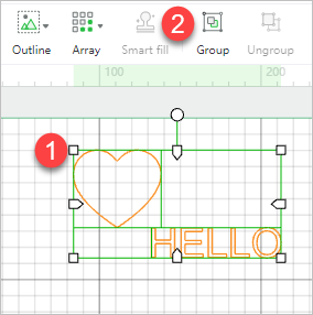
- Smart fill: duplicates a design element for multiple materials. This function is available only for devices with built-in cameras. xTool D1 Pro is equipped with no camera, and therefore it doesn't support this function.
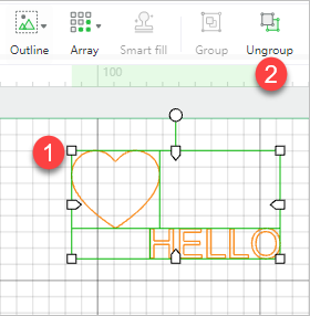
- Group: selects multiple elements and clicks Group to group them
- Ungroup: selects the combined elements and clicks Ungroup to ungroup them
- Align: aligns multiple elements

For example, to align the elements shown in the following figure.

-
- Align left

-
- Horizonral align center

-
- Align right

-
- Align top

-
- Vertical align center
-
- Align bottom

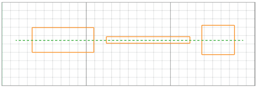
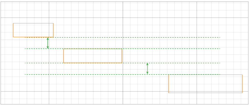
For example, to distribute the elements shown in the following figure.

-
- Distribute horizontally

-
- Distribute vertically
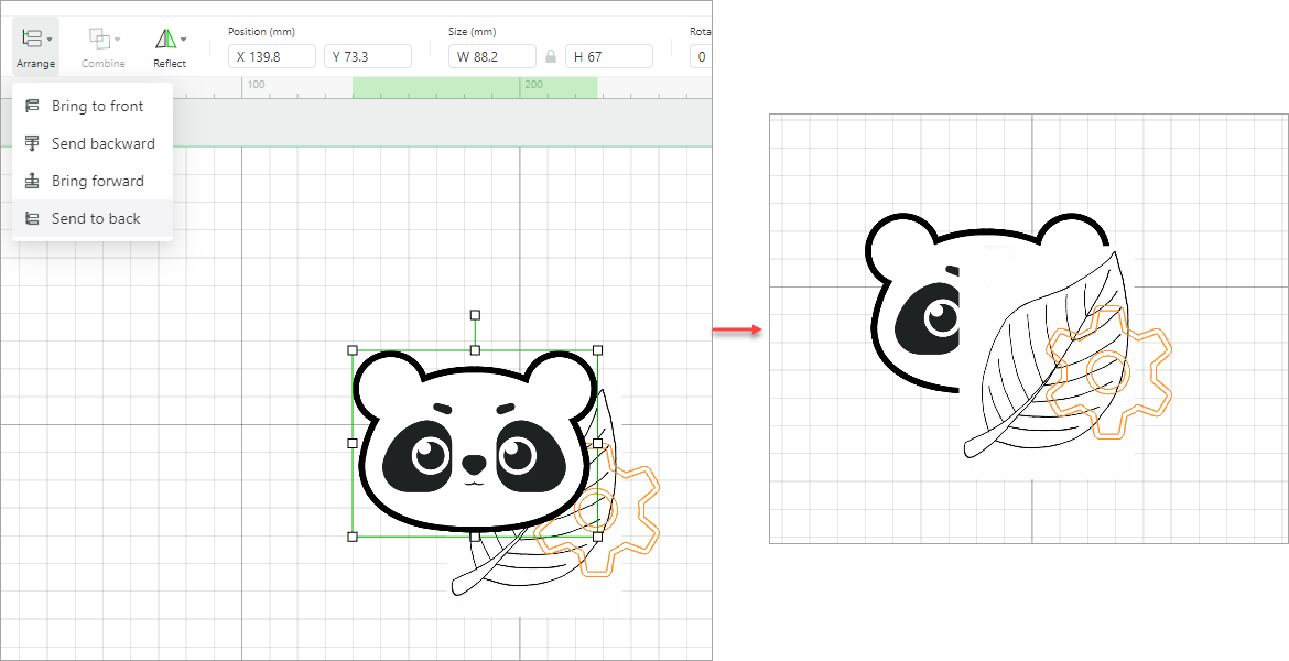
- Arrange: arranges the order of elements. You can bring an element to the front or send it to the back, or bring it forward or send it backward one layer by one layer.
For example, to arrange the elements shown in the following figure.
-
- Bring forward

-
- Bring to front

-
- Send backward

-
- Send to back
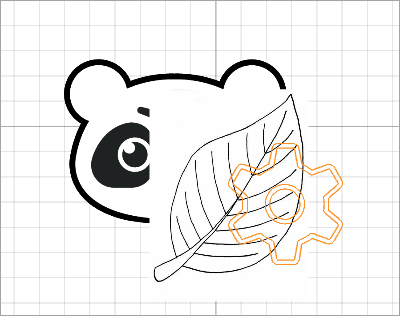
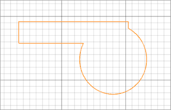
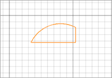
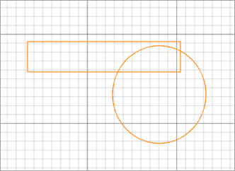
- Combine: combines two or more elements
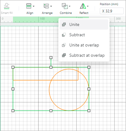
When you unite the two elements:
When you subtract the two elements:
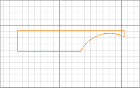
When you unite the two elements at overlap:
When you subtract the two elements at overlap:
- Reflect: reflects an element horizontally or vertically
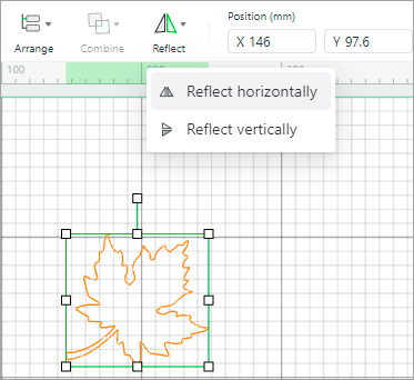
When you reflect the element horizontally:
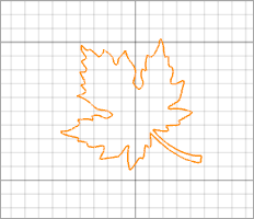
When you reflect the element vertically:
- Position: sets the position of an element on the canvas by the x and y coordinates. The point (0, 0) is in the upper left corner. By default, when you insert a shape or import an image, it is positioned in the upper middle of the canvas. The unit can be set in Settings.
- Size: displays or sets the size of an element. The unit can be set inSettings.

Tips: The width-to-height ratio of an image or element is locked when you import or insert it on XCS. You can click the lock icon to unlock the ratio so that you can change the width and height of the image or element as you like.
- Rotate: rotate an element by angle. A positive value indicates rotating clockwise, and a negative one indicates rotating counterclockwise.

Canvas
Design and edit elements
On the canvas, you can design elements or set and edit an imported image for processing a material.
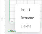
Manage canvases
You can add, delete, or rename a canvas. A project file can include multiple canvases to store multiple design elements.
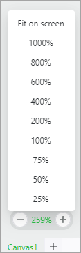
Zoon in/out the canvas
You can zoom in or out the canvas or fit the canvas on screen. The maximum zoom-in scale is 4000%. After setting the scale to 1000%, you can click "+" to further zoom in the canvas.
Device settings
Connect a device
Note:
- Whatever way you want to connect your device to XCS, you need to connect it to XCS by using a USB cable for the first time.
- After you connect your device to XCS through Wi-Fi or IP address, XCS can search for and find your device automatically, and you don't need to connect them through a USB cable.
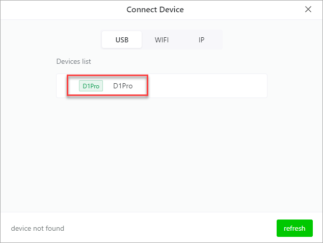
USB connection
1. Use the USB cable to connect xTool D1 Pro to your computer, turn on it, and open XCS.
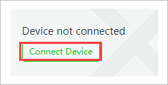
2. Click Connect Device on XCS.
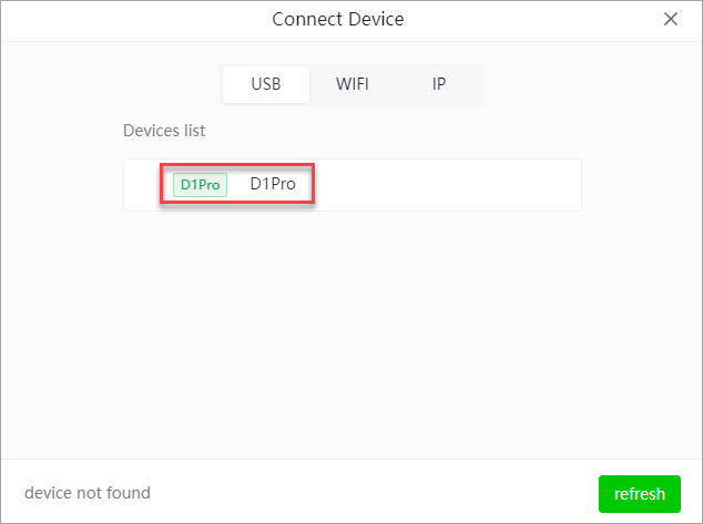
Wait for XCS to search for available devices.
3. Select your device.
Wi-Fi connection
1. Use the USB cable to connect xTool D1 Pro to your computer, turn on it, and open XCS.
2. Click ConnectDevice on XCS.
Wait for XCS to search for available devices.
3. Select your device.
4. After connecting your device to XCS through the USB cable, you can click the settings icon to open the device information and settings window. Click Settings in Wi-Fi setting to configure the Wi-Fi network.
If you have connected your device to XCS through Wi-Fi network, you can find your device on the WIFI tab after XCS searches for devices.
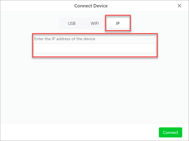
IP connection
You can enter the IP address of you device on XCS to connect it.
1. After connecting your device to XCS through a USB cable, you can find the IP address of the device in the device information and settings window.
2. Enter the IP address on the IP tab in the Connect device window.
View device information and set its functions
After connecting xTool D1 Pro to XCS, you can view basic info and set functions for it.
Basic info.
- Device name: sets the name of your device
- Laser model: displays the model of the laser module
- Serial number: displays the serial number of your device
- Firmware version: displays the firmware version of the device. You can click Check for updates to check for later versions and update the firmware.
- Wi-Fi setting: sets the Wi-Fi name and password to set a Wi-Fi connection
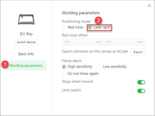
Working parameters
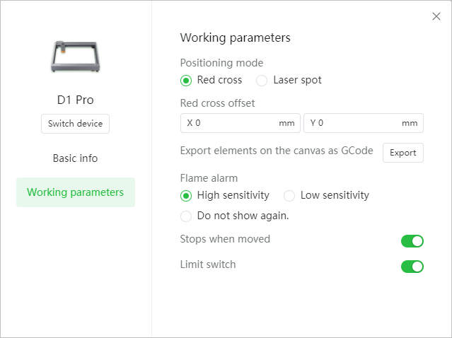
- Positioning mode
- Red cross: Red cross is the default laser positioning mode when you use your machine and XCS for the first time. The center of the red cross can help you to locate the laser beam.
Note:
-
-
- The center of the red cross may be 1 mm to 2 mm away from where the laser beam actually falls. When this happens, you can set the offset to perform calibration.
-

-
- Laser spot: Laser spot refers to a low-power beam emitted by the laser module, which can help you locate the start position for processing. After selecting Laser Spot mode on the Working parameters, you can enable or disable the Laser spot mode on the Preview page.
Tips: In Red cross mode, the processing length along the x-axis is 1 cm shorter than that in laser spot mode. If you want to have the largest processing area, the laser spot mode is recommended.
- Export elements on the canvas as Gcode: Click Export to export the canvas content as the Gcode file. Gcode file can be used in Lightburn. (xTool D series support to export Gcode only)
- Flame alarm: sets the sensitivity for flame detection
- High sensitivity: When you select this option, the flame sensor is highly sensitive to open flames and sparks. When detecting an open flame or spark, the flame sensor triggers the smoke alarm, buzzer, and light indicator (blinking red) when the xTool D1 Pro is working.
- Low sensitivity: When you select this option, the flame sensor is less sensitive to open flames and sparks. When detecting an open flame or spark, the flame sensor triggers the smoke alarm, buzzer, and light indicator (blinking red) when the xTool D1 Pro is working.
- Do not show again: When you select this option, the flame sensor doesn't trigger any smoke alarm, buzzer, or light indicator even if it detects open flames and sparks.
- Stops when moved: When the Stops when moved function is enabled, moving the machine quickly when it is working triggers the buzzer and light indicator (blinking red).
- Limit switch: When the Limit switch function is enabled, the moving range of the laser module is limited to prevent it from hitting the side plates of the machine.
Processing settings
General settings
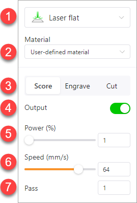
① Processing type
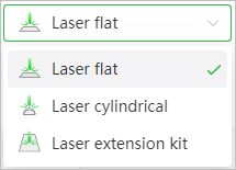
- Laser flat: processes flat materials
- Laser cylindrical: processes cylindrical materials
- Laser extension kit: processes long materials. This process type works only after you extend xTool D1 Pro with the extension kit. You can purchase the extension kit at xtool.com.
② Material
③ Processing mode
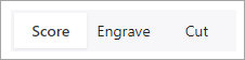
Select an element and set the processing mode.
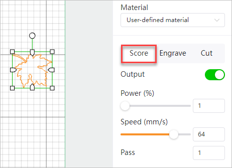
- Score: engraves only the outline of an element
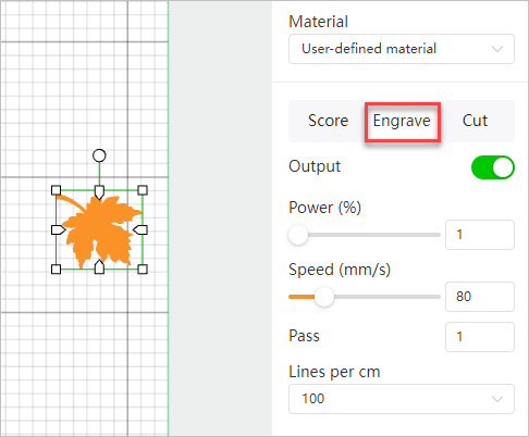
- Engrave: engraves the fill of an element
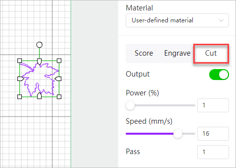
- Cut: cuts the outline of an element
④ Output

Sets whether an element is to be processed.
When you select an element and enable Output, the element is processed based on the parameter settings (processing mode, power, speed, and pass). When you disable Output, all the parameter settings for the element do not take effect, the selected element is not detected during framing or displayed in the Preview window, and the element will not be processed.
⑤ Power
Sets the power for engraving or cutting
⑥ Speed
Sets the speed at which engraving or cutting is to be performed
⑦ Pass
Sets the number of processing times
Additional parameters for bitmap engraving
⑧ Engrave
When a bitmap is selected, only the engraving function is available.
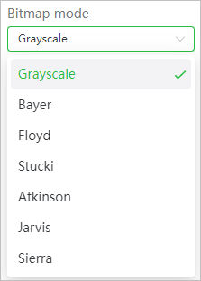
⑨ Bitmap mode
XCS provides multiple bitmap modes, including grayscale, Bayer, Floyd, Stucki, Atkinson, Jarvis, and Sierra. The default mode is grayscale.
- Grayscale
Transforms an image into the grayscale mode. A grayscale image has pixels that are formed by the shade of gray between black and white, which may be the darkest one in black or the brightest one in white. The darker the grayscale pixel, the deeper the engraving.
- Bayer
Looks like adding a special grid mosaic filter to an image.
- Floyd
Dithers the image by using the Floyd algorithm that diffuses the error to neighboring pixels. And the dithering is extremely subtle, resulting in a fine, less distorted, and detailed image. It is recommended for highly-detailed images but not for images with monochrome.
- Stucki
Stucki is a dithering mode that processes slightly faster than Jarvis mode and produces a cleaner and sharper image.
- Atkinson
Dithers is a similar algorithm to Jarvis and Sierra that preserves details well. But we do not recommend using it in a very dark or bright environment, where exposure may occur.
- Jarvis
Jarvis is a dithering mode that provides a softer transition between pixels than Floyd mode and renders good results on almost all images.
- Sierra
Sierra dithers based on Jarvis mode and they process with similar results on images. But the sharpness of Sierra is higher.
With the other settings unchanged, the output of an image on a wooden board varies according to image mode, as shown in the following figure. You can select a mode as required.

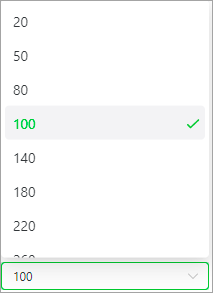
⑩ Lines per cm
Sets the number of lines in one centimeter. This parameter determines the resolution of the image to be engraved.

⑪ Engraving mode
Start processing
After setting the parameters, click Process to start processing the material.
The Preview window is displayed.
- Move laser module: Moves the laser module forward, backward, to the left, or to the right. You can click the middle button and the laser module returns to the origin.
- Speed: sets the speed at which the laser module moves; setting range: 1–150 (mm/s)
- Distance: sets the distance the laser module moves at each time; setting range: 1-300 (mm)
- Laser spot: Enable or disable the laser spot mode and set the power
- Setting range: 1%-10%
Note:
-
- The laser spot is automatically disabled after you exit the working page or the processing starts.
- To use the laser spot positioning function, you need to select this function in Working parameters.
- Origin: sets the start point of the processing on design elements
- Estimated time: displays the estimated processing time
- Framing settings: supports the settings of power and speed for framing
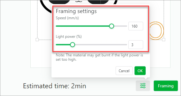
Note:
-
- To set the power and speed for framing, you need to enable the laser spot positioning mode first.
- If the power is set too high, it may leave the burn mark even burn the materials because different materials have different properties. Please adjust the power according to the materials.
- Framing: shows the area to be processed on the material
- Start: If the design elements are to be processed as expected in the expected area, click Start to start the processing and wait for the processing to complete.
- Cancel: cancels the processing and goes back to the canvas
Pause, continue, and cancel processing
- In material processing, you can click Pause and Continue on XCS or press the button on xTool D1 Pro to pause and continue the processing , respectively.
You can click Cancel in the upper right corner of the Processing window to cancel a processing task, whether it is being performed or paused.
Services & Help
Learn & Education

Copyright © 2025 xTool All Rights Reserved.