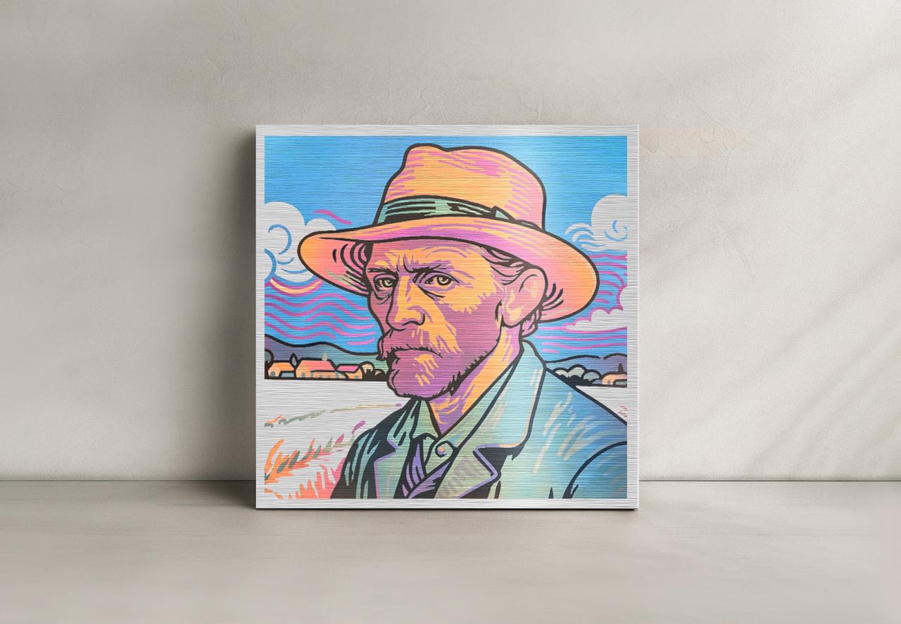
The color engraving technology enables multi-color effects on specific materials. To achieve these effects, just like the image shown below, you can work with xTool F2 Ultra series which supports color engraving of vector fill images and bitmap objects.
Note: The processing files and effect examples provided in this tutorial are primarily based on MOPA infrared laser color engraving on 304 stainless steel. However, you can refer to this method to explore color marking applications on other metals such as brass and titanium.
Importance of color engraving settings
Color formation mechanism on stainless steel
- Oxide coloration
Under laser irradiation, stainless steel's metallic elements produce colored oxidation products. - Transparent oxide film (thin-film interference)
A transparent oxide layer forms, creating color through light interference effects.
Key findings & recommendations
Minor variations in power, focus, or energy can significantly alter the engraved color. For consistent results, calibrate personalized color-engraving parameter settings based on your machine’s performance. Once saved, these settings may help to streamline future engraving workflows.
Before color engraving
Color engraving results can be affected by multiple factors including laser energy, material type, ambient humidity, and temperature fluctuation.
In this case, you're advised to first test your material with a parameter array to identify desired colors, then record and save the corresponding settings for consistent, high-quality output.
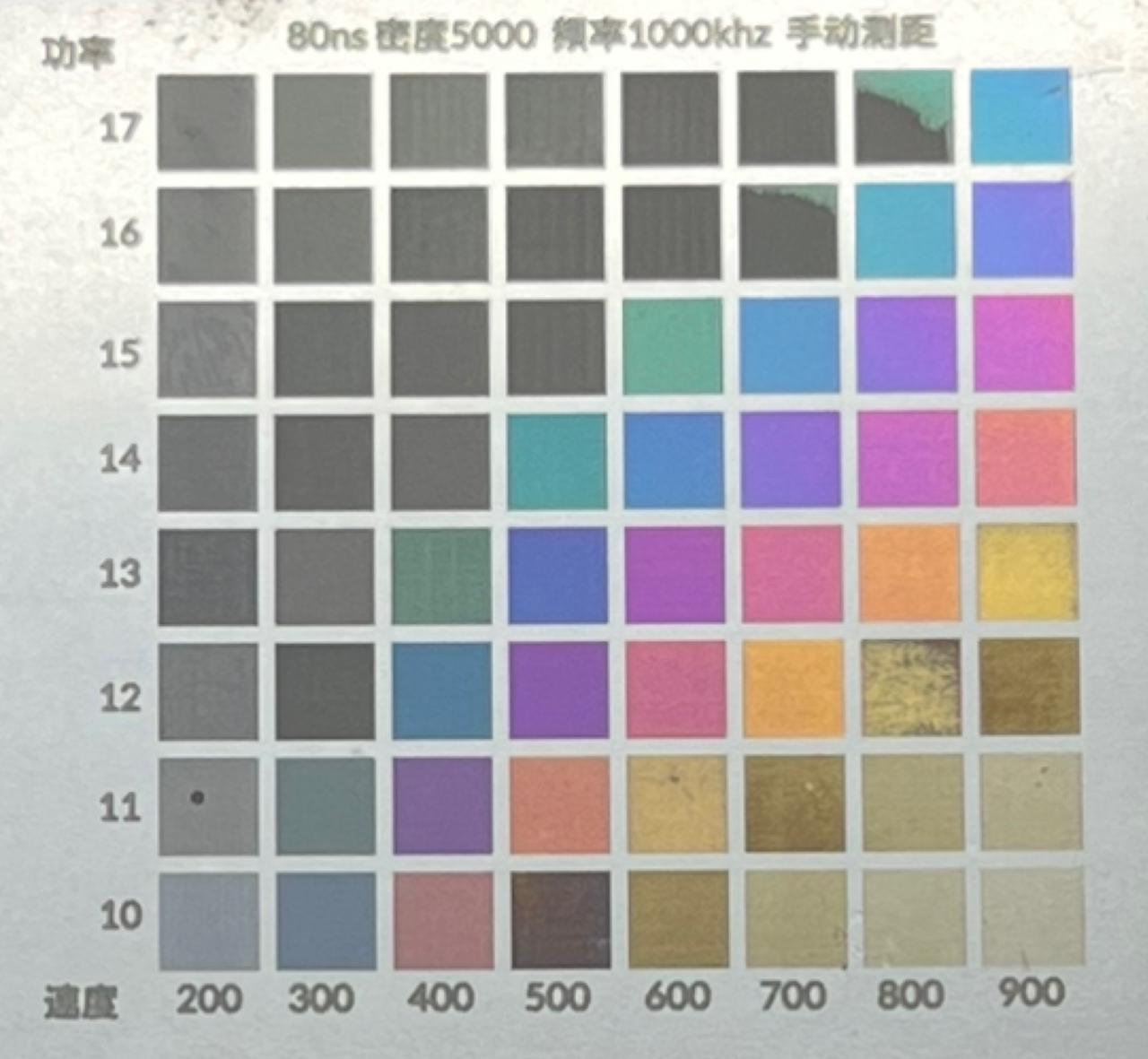
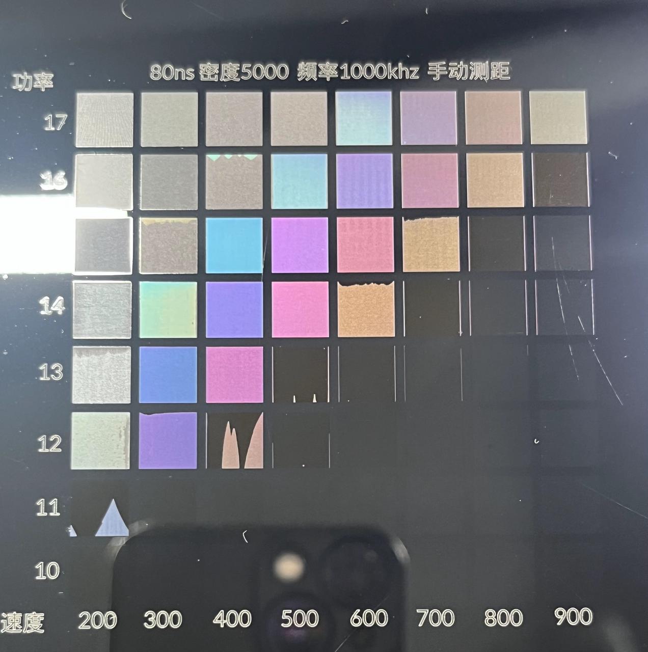
Test color engraving with an array
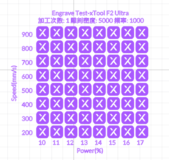
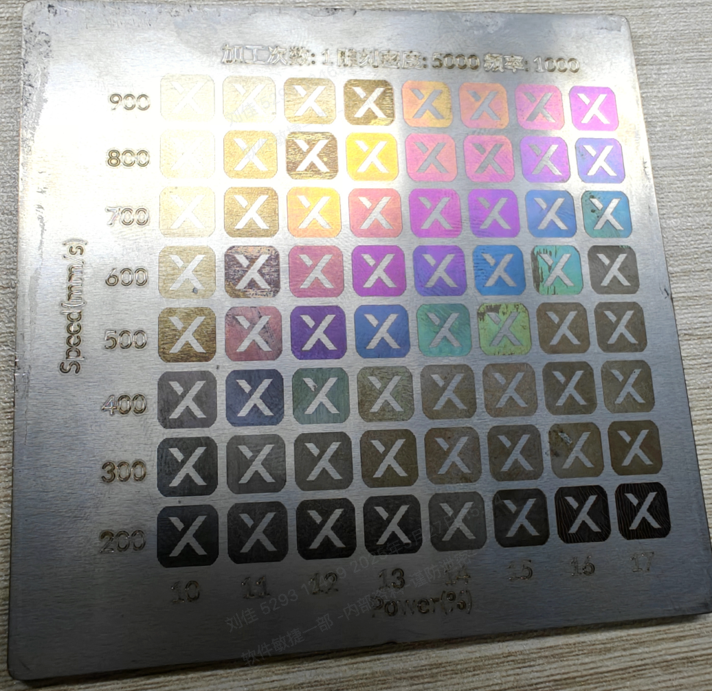
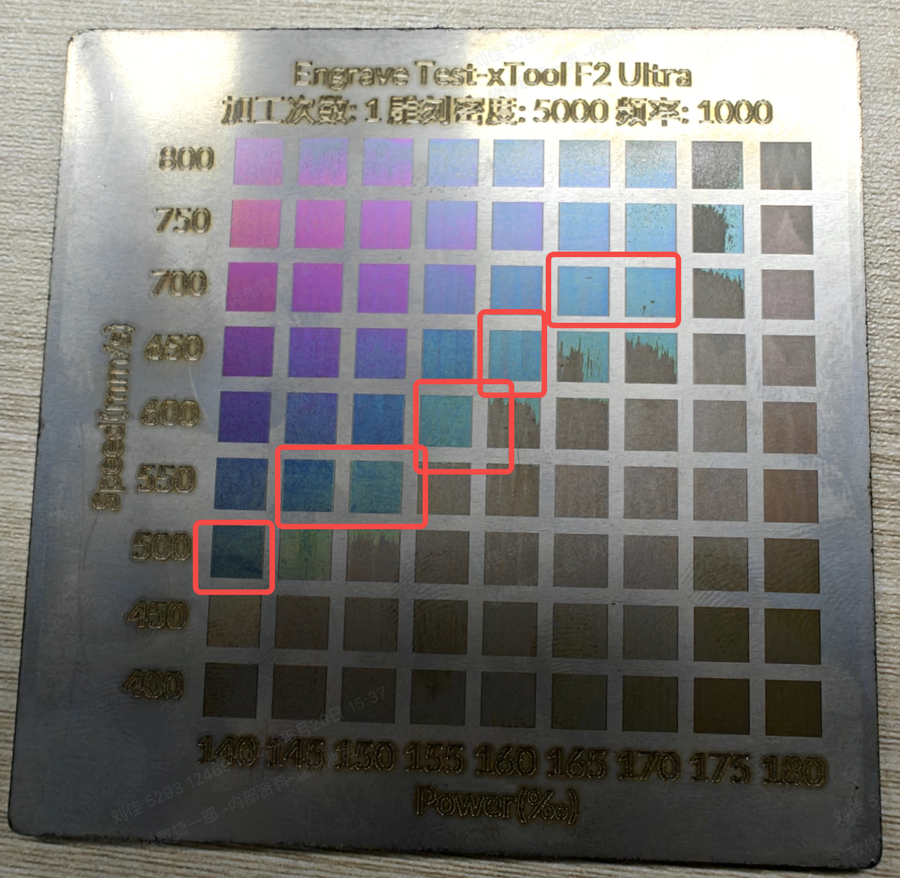
Test example images
|
|
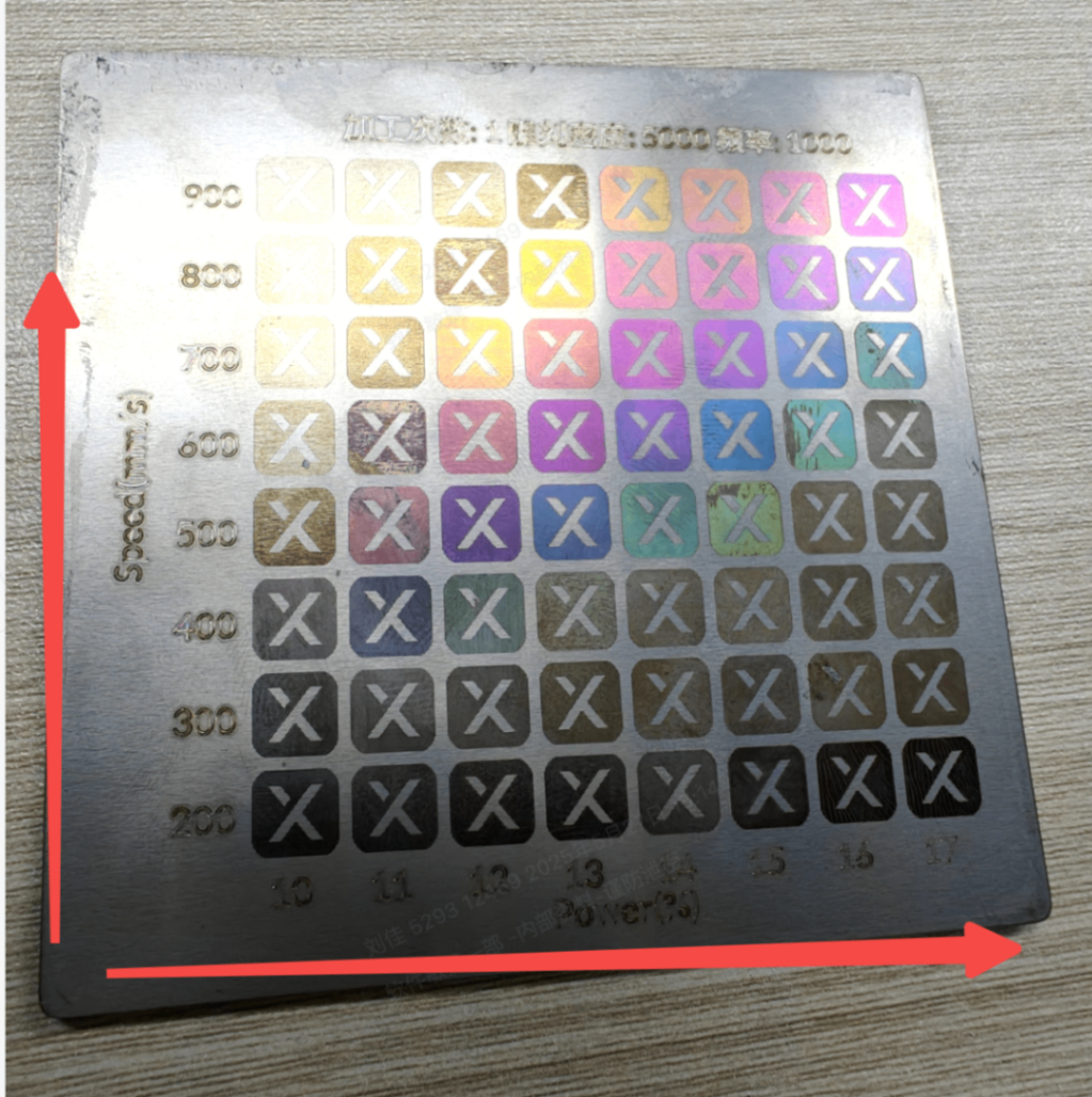
Test array in XCS | Actual processing results on material |
Test procedures
- Download the test array file and open it in XCS.
Test array for xTool F2 Ultra (single-laser model)
Test array for xTool F2 Ultra (dual-laser model) - Use 304 stainless steel (SUS304) and process it after focusing and conducting necessary machine settings in XCS.
Note: To ensure the optimal results, please place the objects to be engraved within 60 x 60 of the center of the baseplate.
- After processing, evaluate the results and proceed as follows:
- If satisfied with a color outcome in a specific grid, mark down those parameter settings including the processing speed and power.
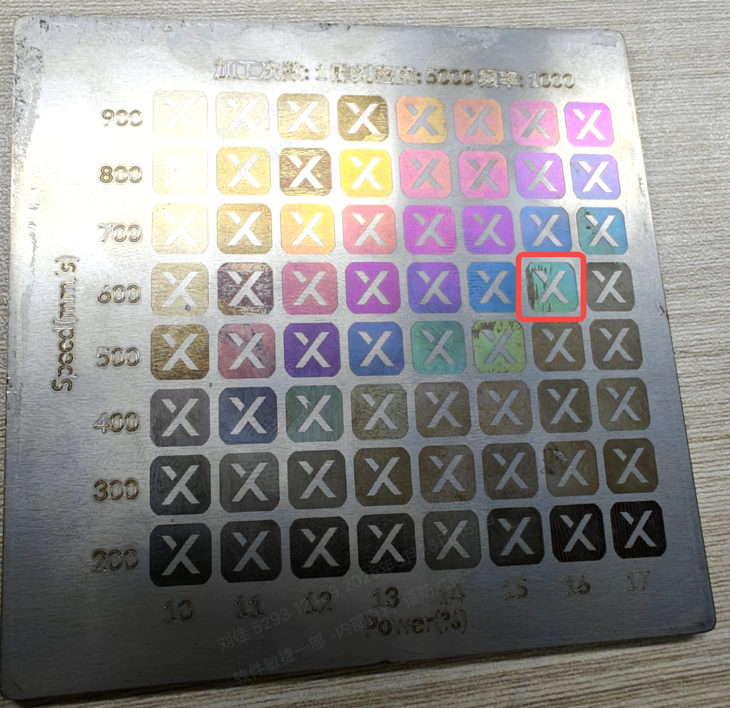
- If seeking improved colors, locate the target color and its corresponding processing speed and power, then create a bidirectional gradient test array by adjusting settings in decrements or increments of 0.5% power and 50 mm/s speed.
For example, to optimize cyan coloration (currently set at 16% power and 600 mm/s speed), generate a test array using these parameters as your baseline, then systematically adjust values in:
- Power: ± 0.5% increments (e.g., 15.5% or 16.5%)
- Speed: ± 50 mm/s increments (e.g., 550 mm/s or 650 mm/s)
|
|
Original test array | Adjusted test array |
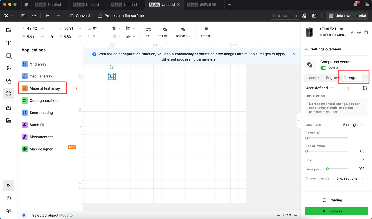
Set up personalized settings
- Create a test array based on the results you've got in the previous steps.
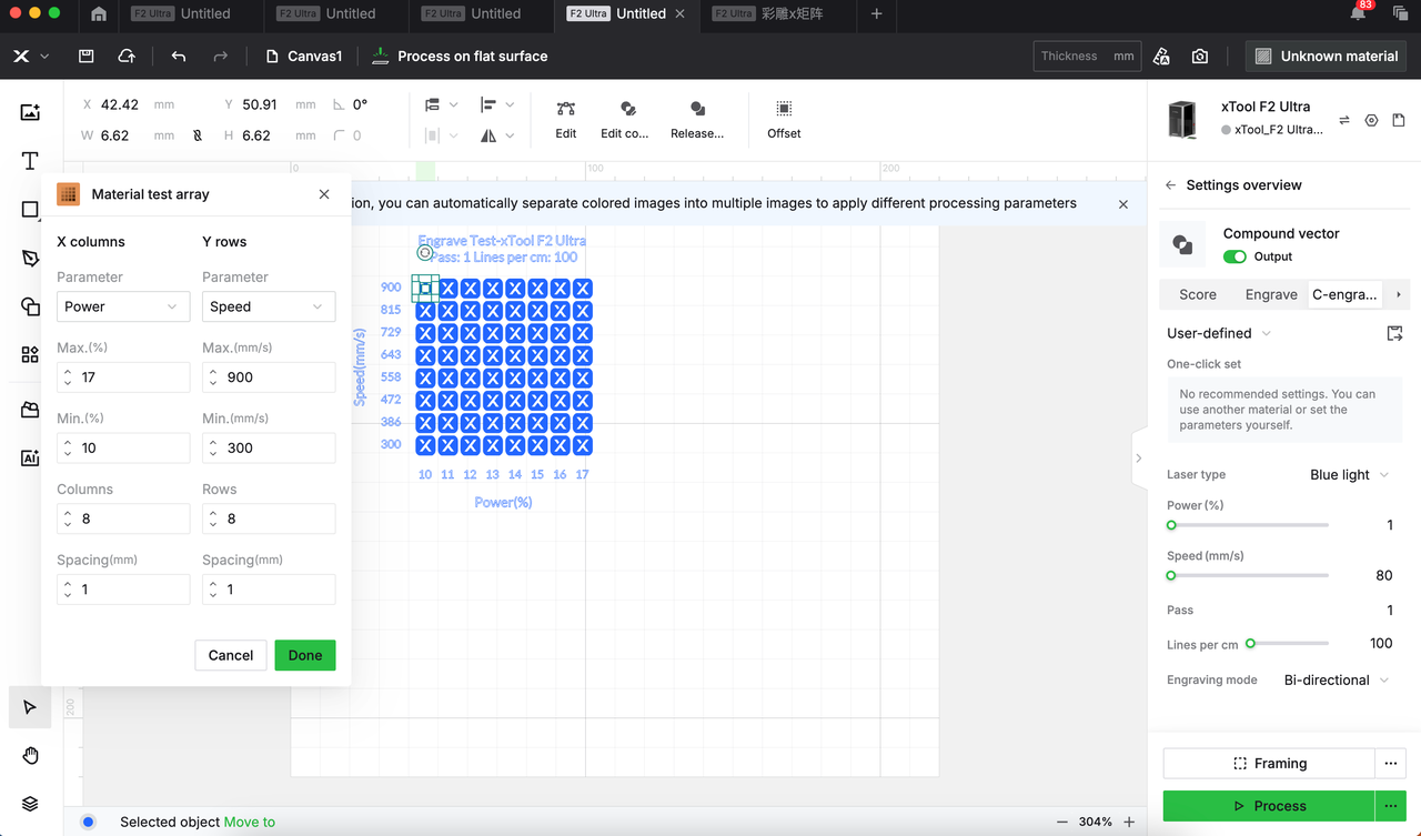
Note: To save the settings in later steps for future use, please use Material test array to set up the array.
Array specifications:
- Minimum single matrix size: 10 mm × 10 mm
- Recommended maximum rows/columns: ≤ 8
- Row/column spacing: ≥ 1 mm
|
|
- Ungroup the test array.
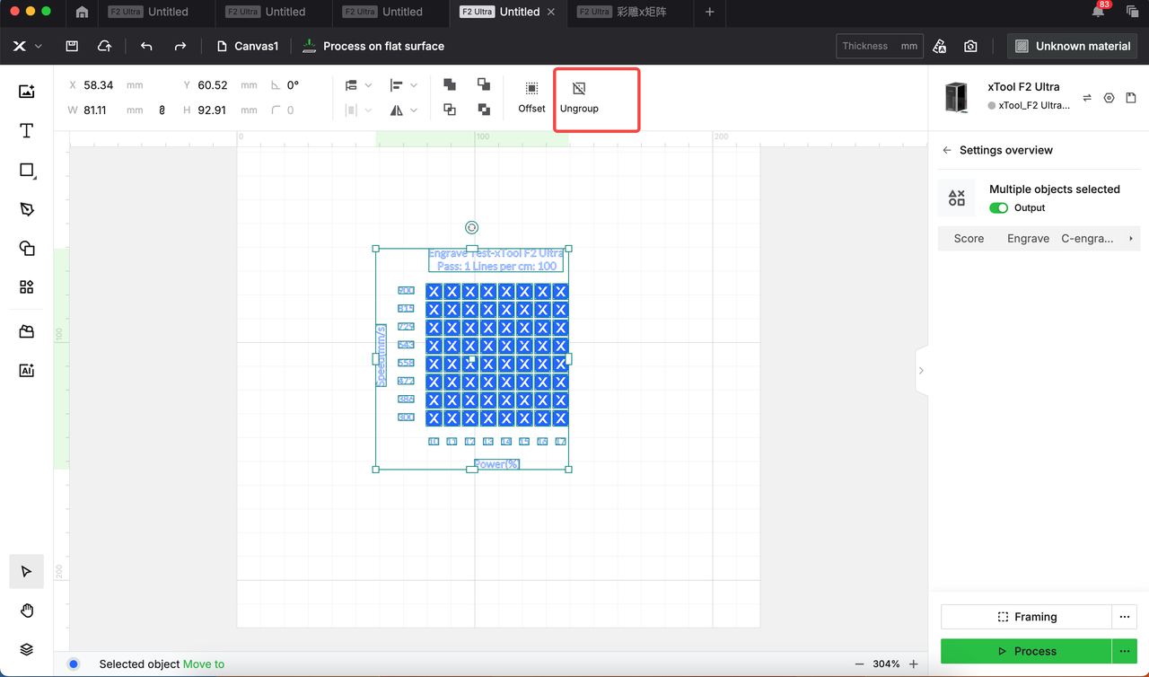
- Click the target grid and save the corresponding settings.
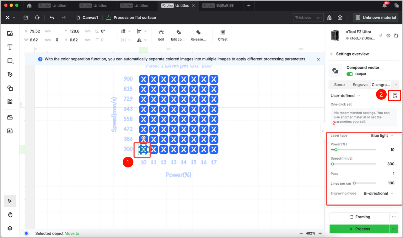
Note: Saving settings helps to speed up the color engraving configuration process. Yet for high-precision requirements, you may need to fine-tune parameters based on actual situation.
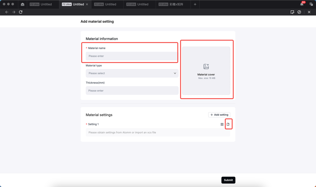
Add setting scheme to XCS
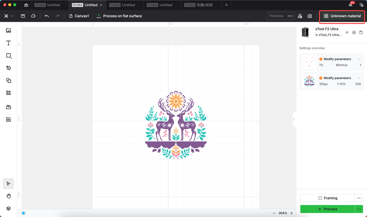
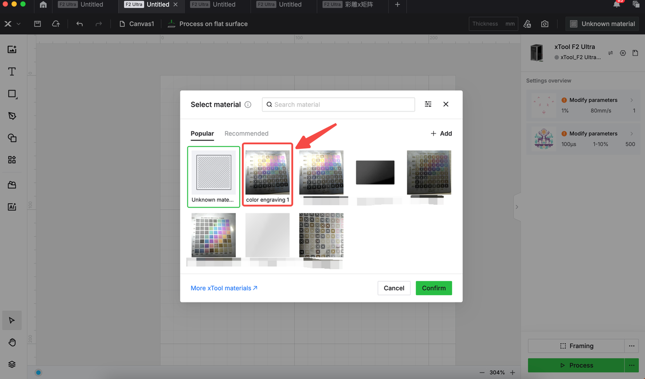
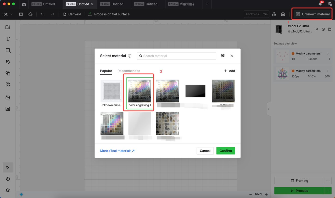
- Click Unknown material in the upper right corner.
- Click +Add.
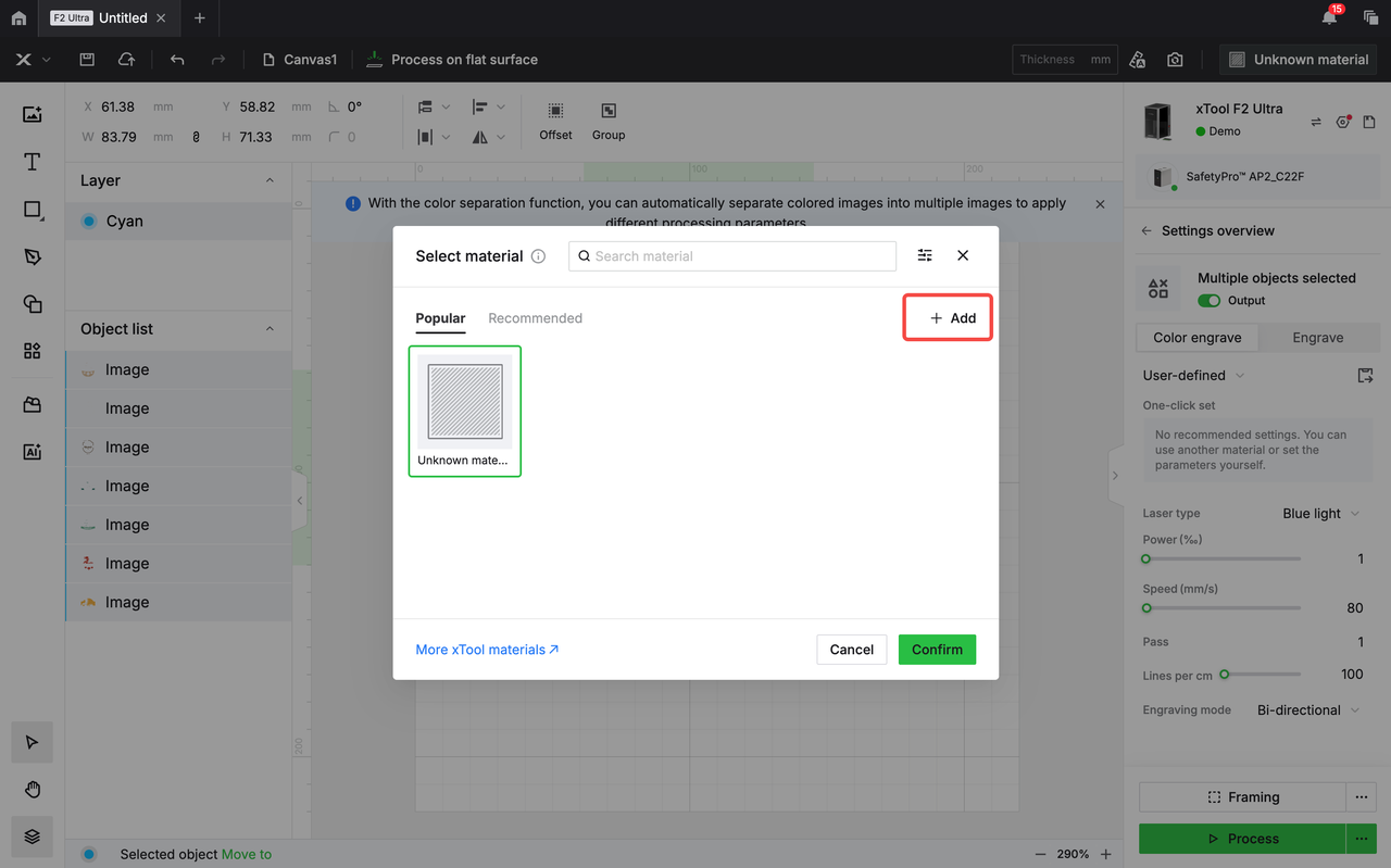
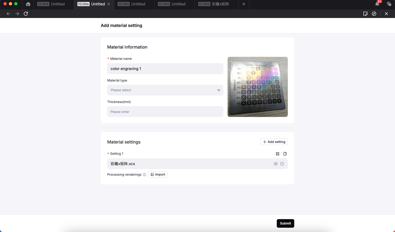
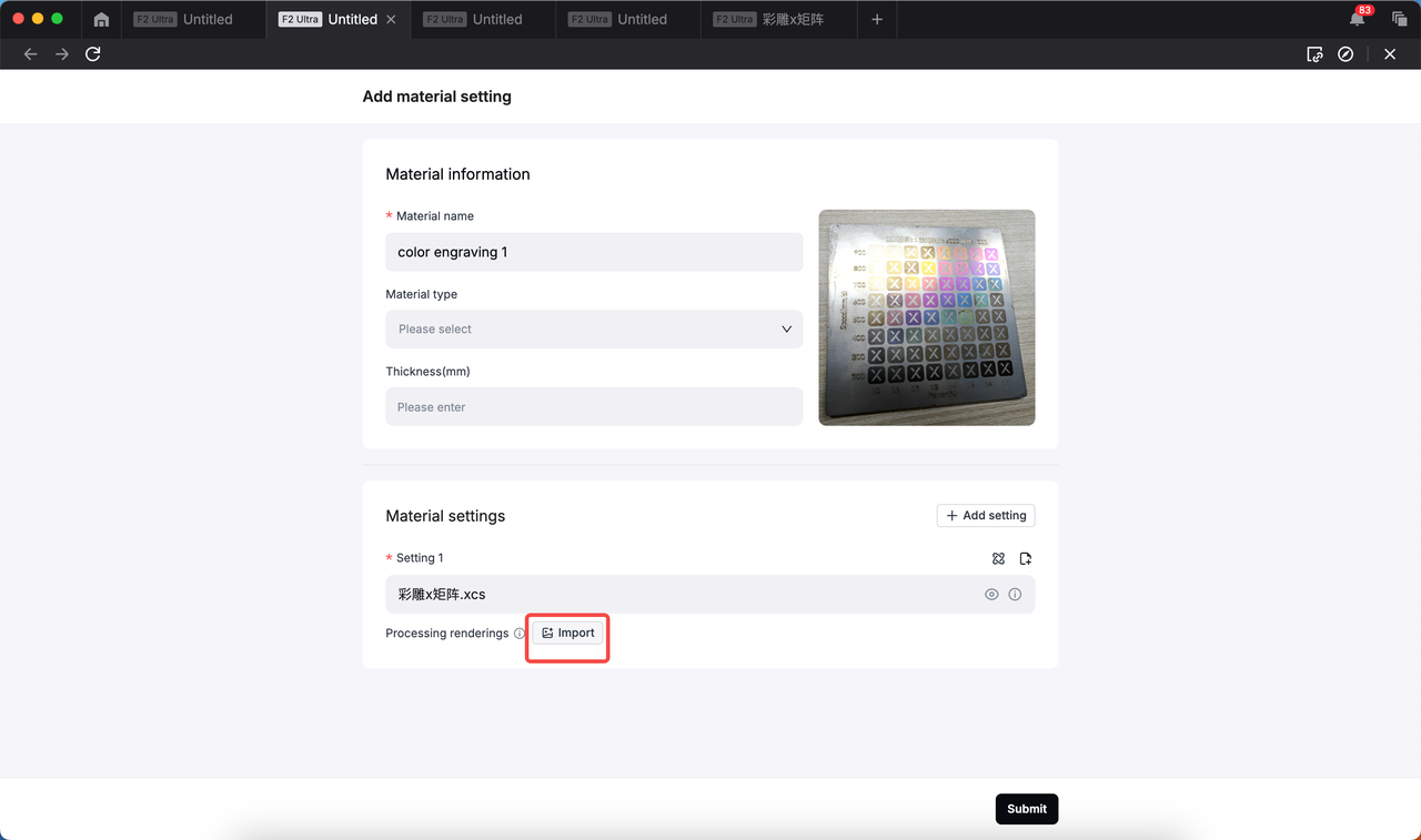
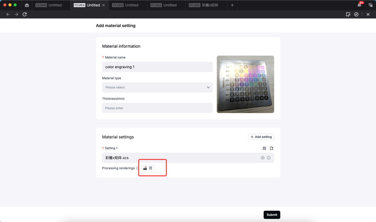
- Fill in the mandatory boxes like material name, image, setting file. Then, click Submit.
Note: The more detailed the information, the more likely you can use the settings with ease in future processing.
About the material image you upload:
* The image should match the uploaded XCS file, including the settings and the orientation.
|
* The image should be captured straight-on to ensure full and clear visibility of the entire test array, row and column names, and each color grid.
|
|
|
|
- Click Unknown material in the upper right corner again and check if the setting is properly saved.
Color engraving steps
- Refer to the user guide to get the machine ready, and place the material to be processed on the machine.
- Connect your xTool F2 Ultra to XCS.
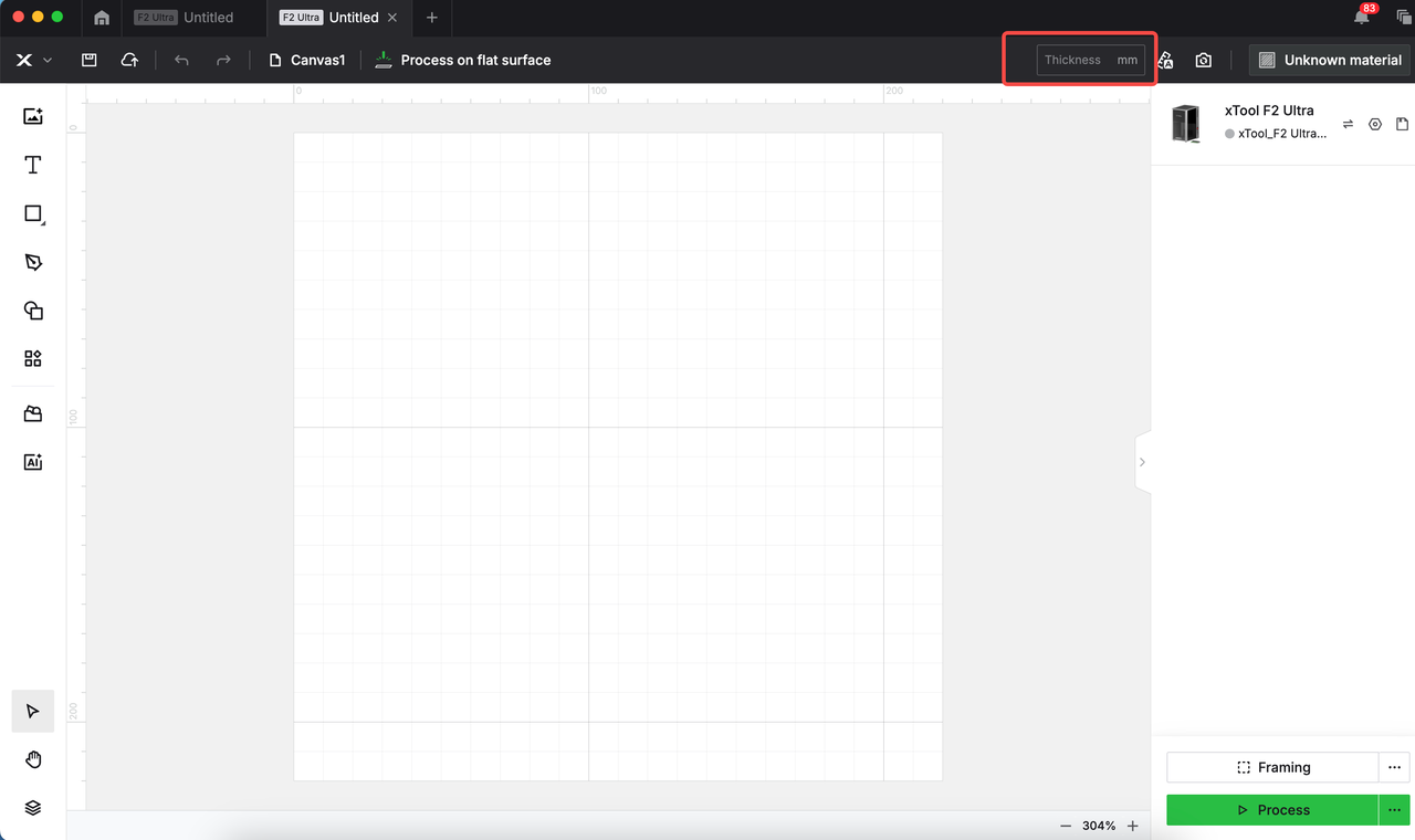
- Follow this to set the focus position.
Note: You are advised to measure the material thickness manually and input the value in the box.
- Click Unknown material in the upper right corner and select the target setting.
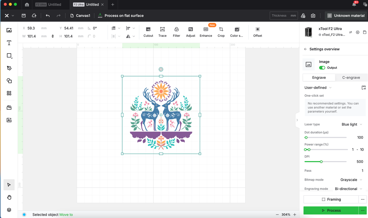
- Import or create a vector fill image or bitmap object.
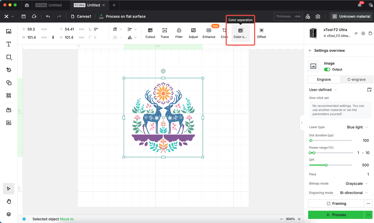
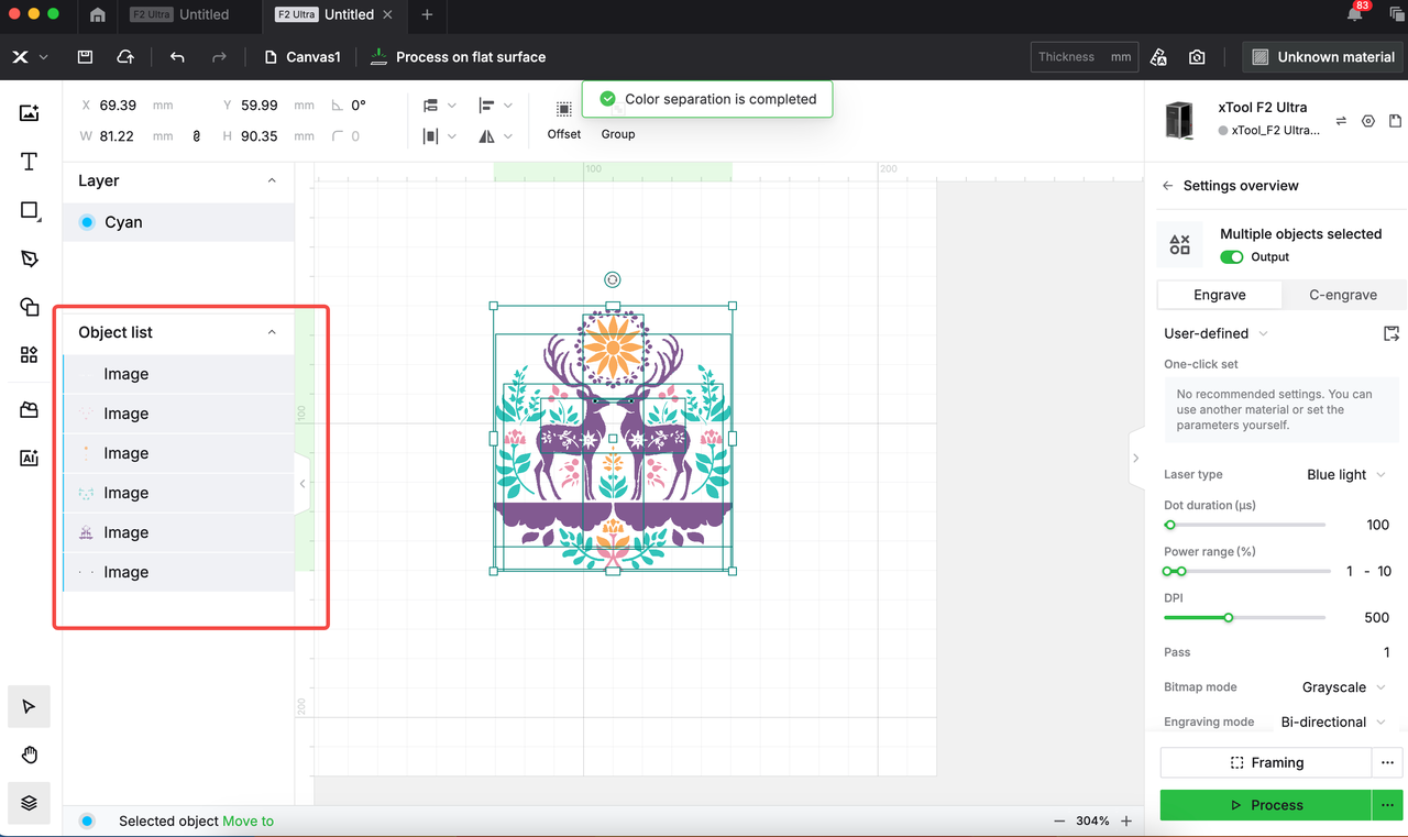
- Click the object. If the object is an image, click Color Separation in the upper bar.
|
|
|
Note:
- If you want to engrave a bitmap image on the material, please ensure that the image meets the following requirements:
* Solid color blocks
* No gradients, transitional colors, or small color pixels
See example:
- Tiny color blocks (with few pixels) can be deleted—they won't noticeably affect the final piece.
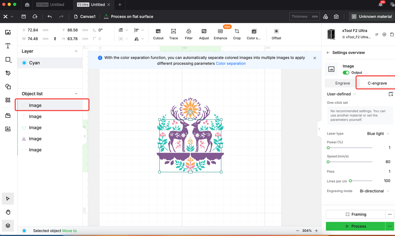
- Click an object part, choose C-engrave in the right panel, and configure processing settings.
- Click Preview processing results of the reference setting under One-click set.
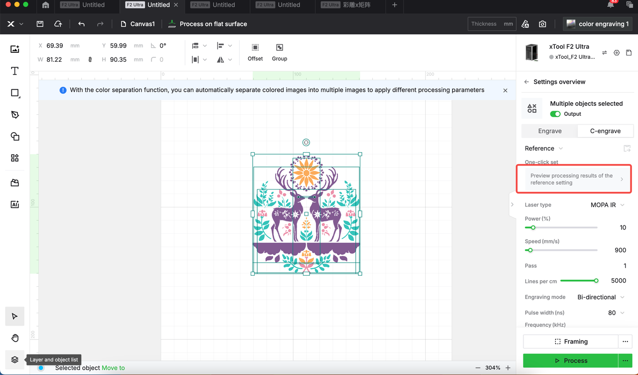
- Repeat the previous step until all parts of the object have been set properly.
- Start processing your material.
Important notes
Processing scope
- This tutorial specifically addresses MOPA infrared laser color engraving on 304 stainless steel.
- The methodology may be adapted for exploring color marking on other metals (e.g., brass, titanium).
Critical processing factors
Color inconsistency may occur even with identical parameter settings due to material inconsistencies, ambient humidity, or temperature fluctuations, which can lead to different oxide layer composition and thickness.
Explore more colors
When it comes to color engraving on 304 stainless steel, the color consistency is sensitive to equipment performance variations, ambient temperature, humidity fluctuations, material surface conditions and consistency, and more.
To help obtain better colors on the material, this section outlines the rules of MOPA laser color engraving on 304 stainless steel, providing useful guidance for parameter adjustment when actual results deviate from target colors.
Color Spectrum Rules
As laser energy increases, colors progress through:
Light yellow → Yellow → Orange → Pink → Purple → Blue-purple → Blue → Cyan → Green → Brown → Black

Parameter Adjustment Rules
|
|
X-axis: Speed Y-axis: Frequency | X-axis: Speed Y-axis: Frequency |
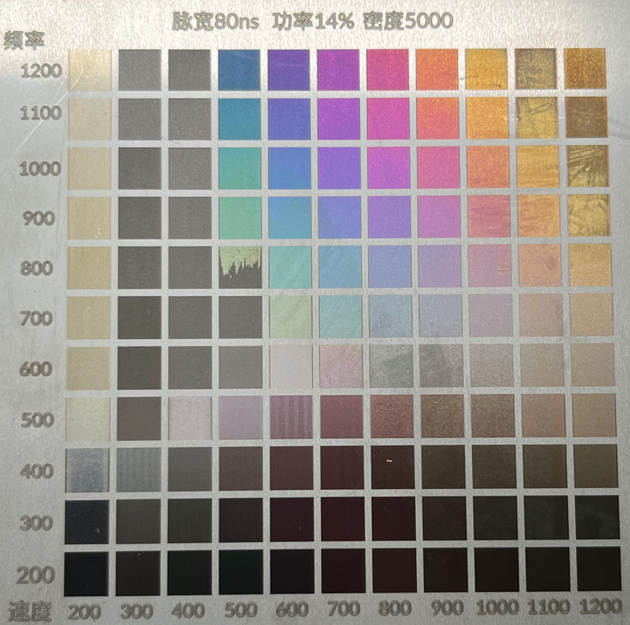
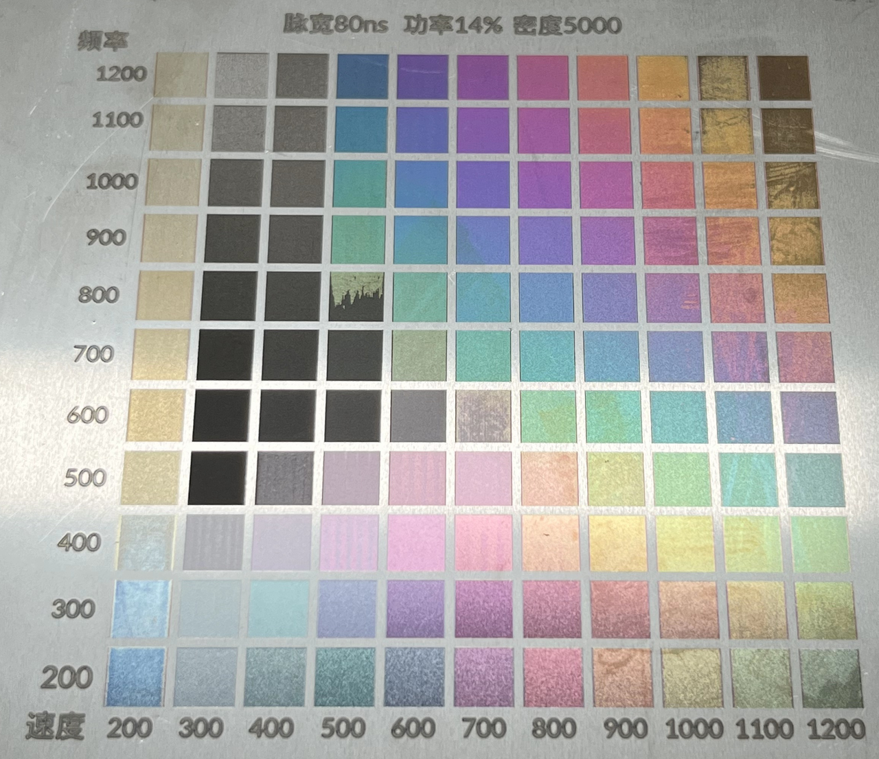
Power:
0.5% increment changes one hue (follow Spectrum Principle)
Speed:
100mm/s increment changes one hue
Frequency:
- Above 500KHz: 100-200KHz changes one hue
- Below 500KHz: Produces special dark colors (black in shadow, colored in light)
Pulse Width:
Recommended >20 ns for visible colors
<20 ns has minimal color effect
Adjustment Strategy:
4+ hue difference: Adjust power/speed
<4 hue difference: Adjust frequency/pulse width
Finish Effect Rules
Different surface finishes affect light reflection on stainless steel, leading to variations in color engraving results even with identical parameters.
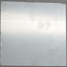
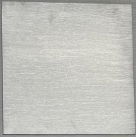
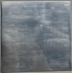
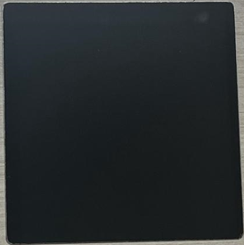
304 stainless steel finish types
|
|
|
|
Mill finish | Brushed finish | Polished finish | Mirror finish |
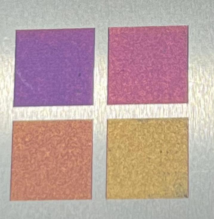
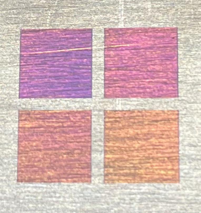
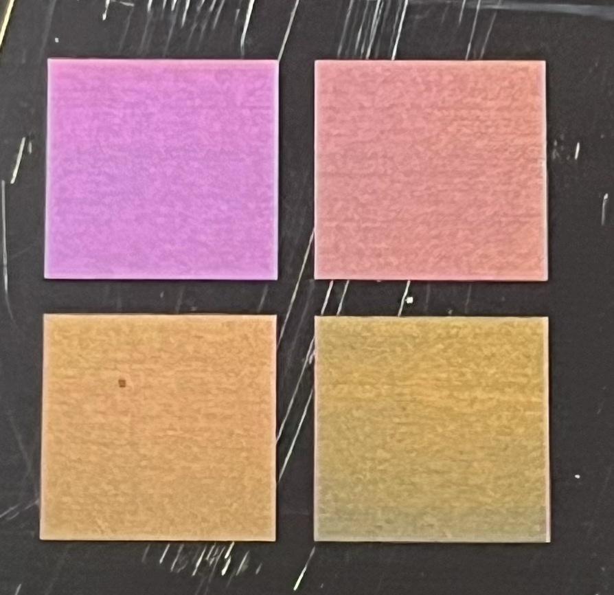
Color engraving results on different 304 stainless steel finishes
|
|
|
|
|
On mill finish | On brushed finish (horizontal) | On brushed finish (vertical) | On polished finish | On mirror finish |
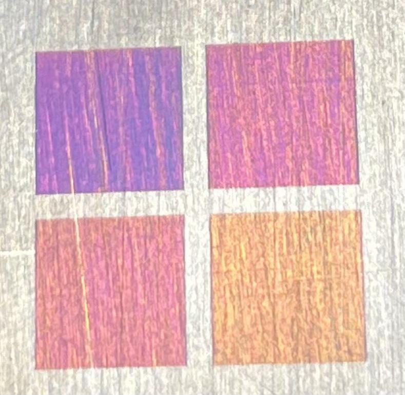
The specific rules are as follows:
- Mill &. Brushed finishes: Minimal difference in color engraving effects.
- Polished & Mirror finishes: Colors on the left side of the test array are produced as those on mill finish under the same parameters.
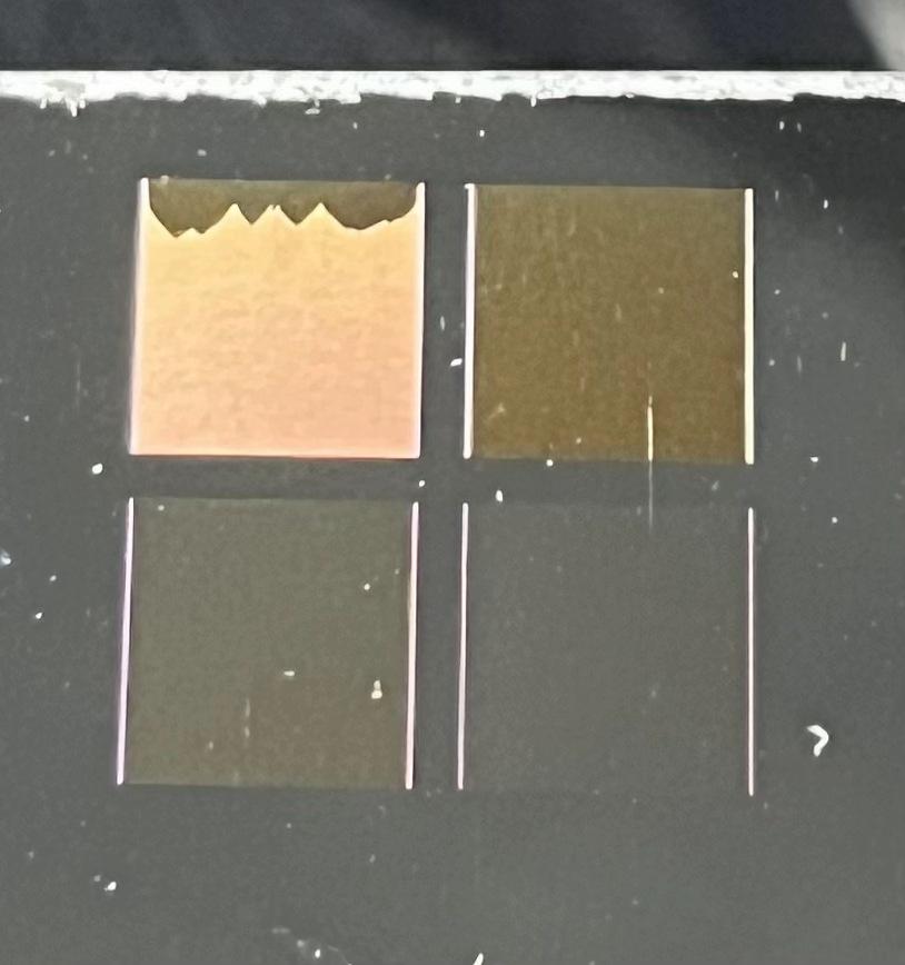
|
|
On mill finish | On polished/mirror finish |
- Energy Compensation Required:
- Polished finish: Increase power by ~1% or decrease speed by 100 mm/s to match colors on the mill finish.
- Mirror finish: Increase power by ~2% or decrease speed by 200 mm/s to match colors on the mill finish.
Note:
- Mirror finishes can be achieved via mechanical or chemical polishing. The mirror finish shown above employs the former technology.
- If your stainless steel is polished via chemical methods, the metal composition may alter, affecting color engraving outcomes.
